Hubbell GAI-TRONICS 210-702BH User manual

Pub. 42004-519C
G A I - T R O N I C S ®
A H U B B E L L C O M P A N Y
Rugged VoIP Autodial Handset Telephones
TA B L E O F CO N T E N T S
GAI-TRONICS 3030 KUTZTOWN RD. READING, PA 19605 USA
610-777-1374 ◼800-492-1212 ◼Fax: 610-796-5954
VISIT WWW.GAI-TRONICS.COM FOR PRODUCT LITERATURE AND MANUALS
Confidentiality Notice.....................................................................................................................1
Product Overview............................................................................................................................1
Features and Functions ..........................................................................................................................2
System Requirements and Limitations.................................................................................................2
Tips for VoIP Subscribers......................................................................................................................2
Operation.........................................................................................................................................2
Place a Call..............................................................................................................................................2
Receive a Call ..........................................................................................................................................3
Handset Receiver Volume Control........................................................................................................3
Monitor and Report Telephone Status..................................................................................................3
Status Indication.....................................................................................................................................3
Power ....................................................................................................................................................3
Heartbeat...............................................................................................................................................3
EACT....................................................................................................................................................3
Installation ......................................................................................................................................4
Safety Guidelines.....................................................................................................................................4
Security Hardware..................................................................................................................................4
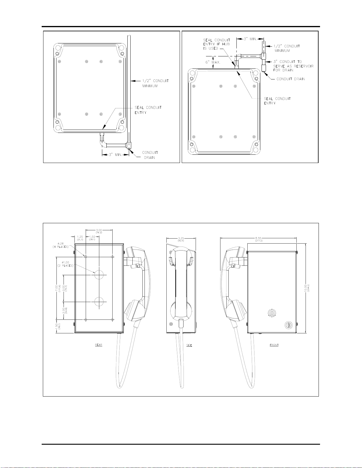
Conduit Installation Details (Applicable to Models 247-700 and 257-700)........................................4
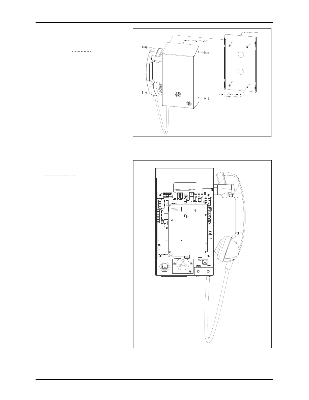
Models 210-702, 210-702BH, and 210-702BHAC.................................................................................5
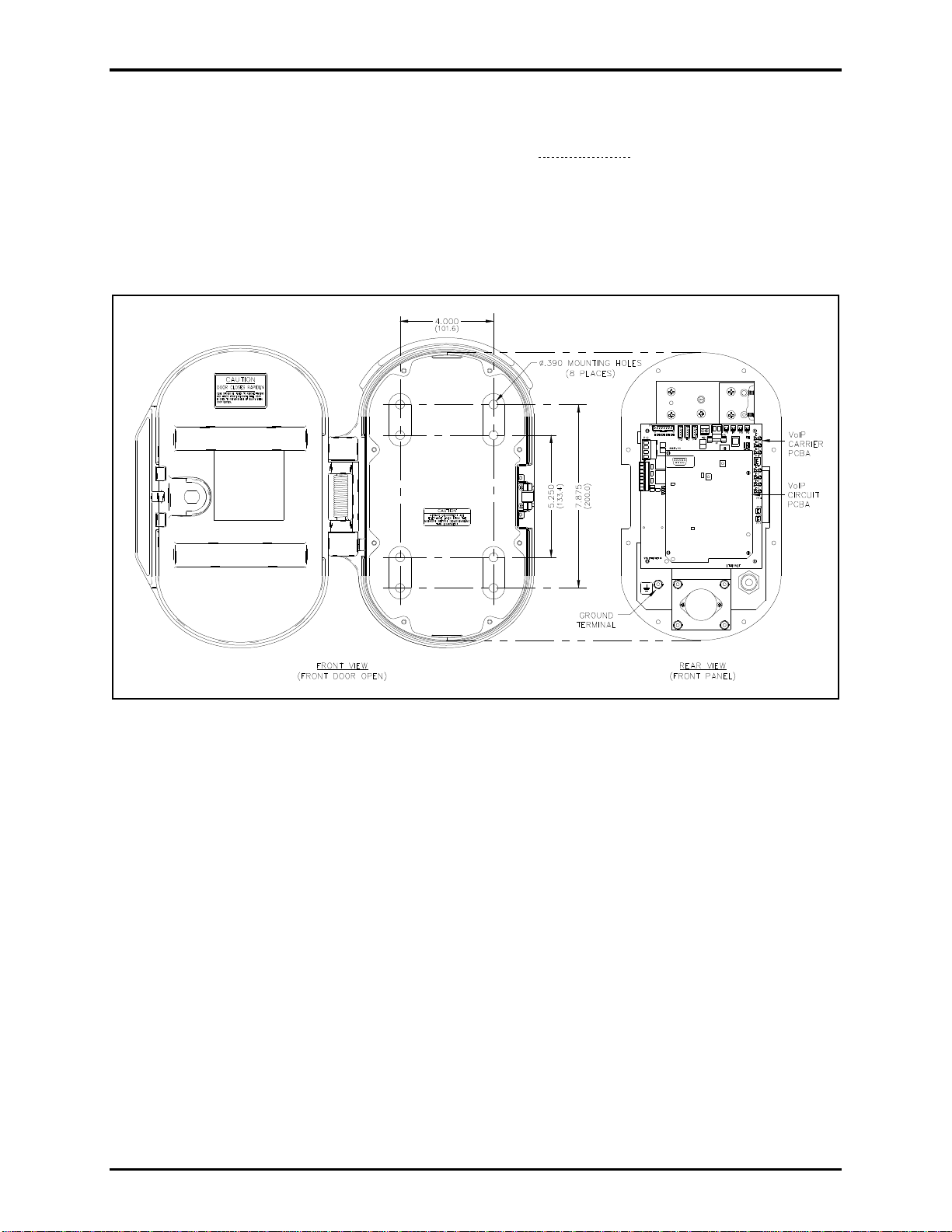
Model 227-700.........................................................................................................................................7
Model 247-700.........................................................................................................................................9
Model 257-700.......................................................................................................................................11
Model 277-700.......................................................................................................................................13
Models 277-702BH and 277-702BHAC...............................................................................................15
Flush-mount Installation.....................................................................................................................15
Surface-Mount Installation .................................................................................................................17
Field Wiring..................................................................................................................................17
Recommended Cabling.........................................................................................................................17
Power......................................................................................................................................................18
Power-Over-Ethernet..........................................................................................................................18
Local Power........................................................................................................................................18
Ground (For Models 210-702BH/-702BHAC, 227-700/-702BH/-702BHAC Only).........................19
Network..................................................................................................................................................19

Table of Contents Pub. 42004-519C
GAI-TRONICS 3030 KUTZTOWN RD. READING, PA 19605 USA
610-777-1374 ◼800-492-1212 ◼Fax: 610-796-5954
VISIT WWW.GAI-TRONICS.COM FOR PRODUCT LITERATURE AND MANUALS
Auxiliary I/O..........................................................................................................................................19
Inputs...................................................................................................................................................19
Outputs................................................................................................................................................20
Programming ................................................................................................................................20
VoIP PCBA Setup.................................................................................................................................20
VoIP PCBA Initial Network Configuration .......................................................................................20
VoIP Telephone Input Contact Configuration...................................................................................21
VoIP Telephone Output Contact Configuration................................................................................21
Maximum (Handset Receiver) Level Remote Control ......................................................................21
Maintenance..................................................................................................................................21
General Information.............................................................................................................................21
Preventive Maintenance for Model 277-700/-702BH/-702BHAC.....................................................21
Cleaning..............................................................................................................................................21
Prevention...........................................................................................................................................22
Service....................................................................................................................................................22
Troubleshooting....................................................................................................................................22
Replacement Parts and Accessories.............................................................................................23
Specifications ................................................................................................................................24
Power......................................................................................................................................................24
Network..................................................................................................................................................24
Handset Audio.......................................................................................................................................24
Inputs .....................................................................................................................................................25
Outputs ..................................................................................................................................................25
Indicators...............................................................................................................................................25
Mechanical.............................................................................................................................................25
Approvals.......................................................................................................................................26

Pub. 42004-519C
G A I - T R O N I C S ®
A H U B B E L L C O M P A NY
Rugged VoIP Autodial Handset Telephones
GAI-TRONICS 3030 KUTZTOWN RD. READING, PA 19605 USA
610-777-1374 ◼800-492-1212 ◼Fax: 610-796-5954
VISIT WWW.GAI-TRONICS.COM FOR PRODUCT LITERATURE AND MANUALS
Confidentiality Notice
This manual is provided solely as an installation, operation, and maintenance guide and contains sensitive
business and technical information that is confidential and proprietary to GAI-Tronics. GAI-Tronics
retains all intellectual property and other rights in or to the information contained herein, and such
information may only be used in connection with the operation of your GAI-Tronics product or system.
This manual may not be disclosed in any form, in whole or in part, directly or indirectly, to any third
party.
Product Overview
GAI-Tronics’ VoIP Autodial Handset Telephones are designed for connection to a 10/100 BaseT Ethernet
network. These telephones operate from Power-over-Ethernet (PoE) or an external power source. These
VoIP telephones provide direct point-to-point communications between personnel throughout a facility
over an existing LAN.
The following VoIP Telephones are detailed in this manual:
Table 1. Model Chart
Model
Description
210-702
Corridor VoIP Autodial Telephone with 29-inch armored cord handset.
210-702BH
Behavioral Health VoIP Autodial Telephone with 12-inch armored cord
handset.
210-702BHAC
Behavioral Health VoIP Autodial Telephone with 15-inch armored cord
handset.
227-700
Tough VoIP Autodial Telephone, weather and vandal resistant sand-cast
aluminum enclosure with a spring-loaded door and 15-inch armored cord handset.
247-700
Rugged Indoor VoIP Autodial Telephone, engineered plastic enclosure and
handset with Hytrel®coiled cord (6-foot extended).
257-700
Rugged Weatherproof VoIP Autodial Telephone, weatherproof, engineered
plastic enclosure with door and handset with Hytrel®coiled cord (6-foot
extended).
277-700
Flush-panel VoIP Autodial Telephone, heavy-gauge brushed stainless steel front
panel with 29-inch armored cord handset.
277-702BH
Flush-panel VoIP Behavioral Health Autodial Telephone, heavy-gauge
brushed stainless steel front panel with 12-inch armored cord handset.
277-702BHAC
Flush-panel VoIP Behavioral Health Autodial Telephone, heavy-gauge
brushed stainless steel front panel with 15-inch armored cord handset.

Pub. 42004-519C
Rugged VoIP Autodial Handset Telephones Page 2 of 26
P:\Standard IOMs - Current Release\42004 Instr. Manuals\42004-519C.docx
10/19
Features and Functions
The VoIP Telephones covered in this manual include the following features:
•SIP compatible (RFC3261)
•weather and/or vandal-resistant
•real-time alarm reporting via email, syslog, or TMA software
•PoE (Power-over-Ethernet) compatible
•configurable via web page, serial link or download
•four auxiliary inputs, two volt-free contact outputs
System Requirements and Limitations
These VoIP telephones require Power-over-Ethernet (PoE) or a local 24–48 V dc power source for
operation. Two VoIP telephones can be connected in a peer-to-peer configuration without the need for a
LAN. A 10/100 BaseT Ethernet network with a SIP (Session Initiation Protocol) server is required for
systems containing three or more VoIP telephones. Conferences are limited by the customer’s LAN
media capabilities and the services available at each end point.
Tips for VoIP Subscribers
The following points should be addressed for new and existing subscriptions to an interconnected VoIP
service provider:
•Provide accurate physical address information to the VoIP service provider to ensure that emergency
services can quickly be dispatched to the location.
•Be familiar with the VoIP service provider’s procedures for updating the address and promptly update
address information in the event of a change.
•Have a clear understanding of any limitations of the local 911 service.
•Be aware that VoIP telephone services may not work if the power is out or the Internet connection is
down. Consider installing a backup power supply, maintaining a traditional telephone line, or having
a wireless telephone as a backup.
•For questions about interconnected VoIP and 911, or VoIP in general, see
http://www.fcc.gov/cgb/consumerfacts/voip.html.
Operation
Place a Call
To place a call:
1. Lift the handset from the cradle to take the telephone off-hook.
The programmed number is automatically dialed after approximately one second.
2. Control the handset receiver volume by pressing the volume control pushbutton.
3. The call is terminated by placing handset back in the cradle, the receiving caller hangs up, the defined
timeout of the call duration is exceeded, or via the SIP server.

Pub. 42004-519C
Rugged VoIP Autodial Handset Telephones Page 3 of 26
P:\Standard IOMs - Current Release\42004 Instr. Manuals\42004-519C.docx
10/19
Receive a Call
The VoIP telephone’s ringer sounds when called until the handset is removed from the cradle (taken off-
hook) and a conversation can take place.
Handset Receiver Volume Control
A push-button switch is provided on the front panel for adjustment of the handset receiver volume. When
pressed, it decreases the volume gain from 20 dB to 12 dB, to 0 dB, and back up to 20 dB of the original
signal. After the end of each call the signal gain is automatically set to 20 dB.
Monitor and Report Telephone Status
Each telephone can recognize and generate several hardware and configuration fault condition alarms.
There are three methods to transmit this information to a remote site:
•syslog output over TCP
•SMTP mail message
•TMA (Telephone Management Application) software (purchased separately)
Available alarms are:
•handset integrity loop (if applicable)
•configuration error
•cold reset (power cycle)
•warm reset (internal command)
•key hook (off hook status, if applicable)
•register fail
•audio path test (speaker/microphone test)
Status Indication
Power
The power LED located on the VoIP PCBA illuminates when power is applied to the telephone (see
Figure 18).
Heartbeat
The heartbeat LED located on the VoIP PCBA will flash once network communication is established (see
Figure 18).
EACT
The EACT LED located on the VoIP PCBA turns ON when VoIP PCBA is connected to an Ethernet
device and flashes when data is being transmitted (see Figure 18).

Pub. 42004-519C
Rugged VoIP Autodial Handset Telephones Page 4 of 26
P:\Standard IOMs - Current Release\42004 Instr. Manuals\42004-519C.docx
10/19
Installation
WARNING
—This product can contain hazardous voltages. Always remove power to this
station and any associated equipment before beginning any installation.
CAUTION
—Do not install this equipment in areas other than those indicated on the approval
listing in the Approvals section of this manual. Such installation may cause a
safety hazard and consequent injury or property damage.
Install equipment without modification and according to all applicable local and national electrical codes.
Consult the National Electrical Code (NFPA 70), Canadian Standards Association (CSA 22.1), and local
codes for specific requirements regarding your installation. Class 2 circuit wiring must be performed in
accordance with NEC.
Safety Guidelines
When installing any GAI-Tronics equipment, please adhere to the following guidelines to ensure the
safety of all personnel:
•Do not install wiring during a lightning storm.
•Electrostatic Discharge (ESD) Protection: GAI-Tronics’ VoIP telephones may have an earth
ground terminal provision. Connect this terminal to ground in accordance with all local safety
regulations and the NEC (National Electrical Code). Grounding must be ensured for safe and stable
communications. Do not use long and coiled ground wires. Trim ground wires to the required
length. Use a star configuration whenever possible. Please note proper grounding does not eliminate
the need for lightning protection for the telephone or the telephone system. A Cat5 data line lightning
surge protector is recommended for telephones subject to any electrostatic discharge (e.g. lightning).
•Do not install jacks in wet locations unless the jack is specifically designed for wet locations.
Security Hardware
Models 210-702BH/-702BHAC, 227-700, and 277-702BH/-702BHAC are vandal-resistant. The front
enclosure or panel of these telephones is attached to its mounting plate or enclosure with security screws.
A GAI-Tronics Model 233-001 Security Screwdriver or Torx T-25 security head tip (sold separately) is
required to install the security screws. Models 247-700 and 257-700 Telephones’ front panels are
attached with standard Phillips head screws.
Conduit Installation Details (Applicable to Models 247-700 and 257-
700)
GAI-Tronics recommends installing cabling in conduit to protect against accidental damage and
vandalism. The following points are strongly recommended to prevent moisture from entering the
enclosure:
•Conduit should enter the enclosure from the bottom.
•If entered from the top, the conduit must be internally sealed to prevent moisture ingress.
•Sealed fittings should be installed at all cable entry points.
•Silicone sealant or equivalent must be applied around and inside all conduit entries.
Please refer to Figure 1 and Figure 2.

Pub. 42004-519C
Rugged VoIP Autodial Handset Telephones Page 5 of 26
P:\Standard IOMs - Current Release\42004 Instr. Manuals\42004-519C.docx
10/19
Figure 1. Model 247-700 & 257-700—Bottom
entry conduit installation details
Figure 2. Model 247-700 & 257-700—Top entry
conduit installation details—
(NOT RECOMMENDED)
Models 210-702, 210-702BH, and 210-702BHAC
Figure 3. Models 210-702/-702BH/-702BHAC VoIP Autodial Behavioral Telephones Outline and
Mounting Detail

Pub. 42004-519C
Rugged VoIP Autodial Handset Telephones Page 6 of 26
P:\Standard IOMs - Current Release\42004 Instr. Manuals\42004-519C.docx
10/19
1. Use a GAI-Tronics No. 233-001
Security Screwdriver to remove the
four tamper-resistant cover-panel
screws (see Figure 4).
2. Remove the front cover assembly
and set it aside to expose the four
mounting holes on the mounting
panel.
3. Position the rear mounting panel on
the mounting surface and fasten
with four #10-32 screws (customer
supplied).
4. Pull the Ethernet cable through one
of the two holes and install the
cable (see the Network section).
Two 1-inch diameter entry holes
are provided on the mounting panel
for cable entry.
5. Connect and configure any desired
peripheral devices (see the
Auxiliary I/O section).
6. Perform the initial programming of
the telephone (see the
Programming section).
7. Replace the front cover assembly
and fasten using the four security
screws removed in Step 1. Tighten
the four screws using a GAI-
Tronics No. 233-001 Security
Screwdriver.
8. Test the telephone operation by
calling to and from another
telephone.
9. Test the operation of peripheral
equipment.
Figure 4. Models 210-702/-702BH/-702BHAC
Front Cover Removal
Figure 5. Models 210-702/-702BH/-702BHAC Internal View

Pub. 42004-519C
Rugged VoIP Autodial Handset Telephones Page 7 of 26
P:\Standard IOMs - Current Release\42004 Instr. Manuals\42004-519C.docx
10/19
Model 227-700
The mounting and cabling instructions for the Model 227-700 Telephone are as follows:
1. Remove the eight security screws
from the front panel using a GAI-
Tronics No. 233-001Security
Screwdriver.
2. Remove the front panel and set it
aside.
3. Determine the hole pattern to use
for mounting the telephone (see
Figure 8).
• Use the 7.875 × 4.0-inch hole
pattern for mounting to a wall
(outside pattern).
• Use the 5.25 × 4.0-inch hole
pattern when using the No.
232-001 Pole Mounting Kit
(inside pattern).
4. Insert (four provided) hole plugs
in the unused mounting holes.
5. Position the enclosure on the
mounting surface and secure it with four
fasteners.
• The holes in the telephone enclosure
accept 3/8-inch screws or bolts.
• The Model 232-001 Pole Mounting Kit
includes four 3/8-16 × 1-inch shoulder
bolts with Teflon seal washers.
NOTE: Use only the round head, hexagon
head, or pan head screws that are
provided. Do not use screws designed
to be countersunk for mounting the
enclosure.
6. Install a conduit fitting in one of the 1/2-inch
NPT conduit entrances located at the top and
bottom of the unit.
The bottom location is preferred (see Figure 7).
7. Insert the conduit into the fitting.
8. Plug the unused access hole with the provided
3/8-inch Allen drive plug.
NOTE: Use silicone sealant or equivalent
around and inside all conduit entries.
9. Pull the Ethernet cable through the conduit and
install the cable (see the Network section).
10. Connect peripheral devices (see the Auxiliary
I/O section).
Figure 6. Model 227-700 VoIP Autodial Telephone
with spring loaded door in the open position
Figure 7. Model 227-700 Outline

Pub. 42004-519C
Rugged VoIP Autodial Handset Telephones Page 8 of 26
P:\Standard IOMs - Current Release\42004 Instr. Manuals\42004-519C.docx
10/19
11. Seal the conduit entry point(s).
NOTE: Use silicone sealant or equivalent around and inside all conduit entries.
12. Perform the initial programming of the telephone (see the Programming section).
13. Verify telephone operation by calling to and from another telephone.
14. Verify the operation of peripheral equipment.
15. Replace the front panel assembly and secure it using the eight front panel security screws.
16. Torque the screws to 10–12 lb⋅in (1.1–1.4 Nm).
Figure 8. Model 227-700 Mounting Detail

Pub. 42004-519C
Rugged VoIP Autodial Handset Telephones Page 9 of 26
P:\Standard IOMs - Current Release\42004 Instr. Manuals\42004-519C.docx
10/19
Model 247-700
The mounting and cabling instructions for
the Model 247-700 Telephone are as
follows:
1. Remove the four screws from the front
panel.
2. Remove the front panel and set it aside.
3. Mount the enclosure to a wall using
either four ¼-20 machine screws with
washers and nuts or four #14 wood
screws of the appropriate length,
depending on the mounting surface.
There are four mounting holes in the
rear enclosure (see Figure 10).
4. Drill a hole for the type of bushing to be
used.
5. Pull the Ethernet cable through the
bushing and install the cable (see the
Network section).
6. Seal the conduit entry point.
NOTE: Use silicone sealant or equivalent around and inside all cable/conduit entries.
7. Connect and configure any desired peripheral devices (see the Auxiliary I/O section).
8. Perform the initial programming of the telephone (see the Programming section).
9. Verify telephone operation by calling to and from another telephone.
10. Test the operation of peripheral equipment.
11. Replace the front panel assembly.
12. Secure the front panel using the four front-panel screws.
13. Torque the screws to 10–12 in∙lb (1.1–1.4 N∙m).
Figure 9. Model 247-700 VoIP Autodial Telephone

Pub. 42004-519C
Rugged VoIP Autodial Handset Telephones Page 10 of 26
P:\Standard IOMs - Current Release\42004 Instr. Manuals\42004-519C.docx
10/19
Figure 10. Model 247-700 Mounting Detail

Pub. 42004-519C
Rugged VoIP Autodial Handset Telephones Page 11 of 26
P:\Standard IOMs - Current Release\42004 Instr. Manuals\42004-519C.docx
10/19
Model 257-700
The mounting and cabling instructions for
the Model 257-700 Telephone are as
follows:
1. Open the front door and remove the
four outer screws from the mid-section.
2. Carefully pull the enclosure apart until
encountering a slight resistance on the
left side.
3. Pull on the left side of the enclosure
until the hinge plugs pull loose to
separate the front and rear halves.
4. Set the front half of the enclosure aside.
5. Mount the enclosure on the wall using
four ¼-20 machine screws with nuts
and washers or #14 wood screws of the
appropriate length for the mounting
surface.
There are four mounting holes in the
rear enclosure.
6. Drill a hole for the type of bushing to
be used.
7. Reinsert the hinge pins to attach the front half of the enclosure.
8. Insert the Ethernet cable through the gland bushing and install the cable (see the Network section).
NOTE: Conduit may be used in place of the provided gland bushing. If used, the conduit entrance
must be sealed after the cable is installed.
NOTE: Use silicone sealant or equivalent around and inside all conduit entries.
9. Connect peripheral devices (see the Auxiliary I/O section).
10. Perform the initial programming of the telephone (see the Programming section).
11. Verify telephone operation by calling to and from another telephone.
12. Test the operation of peripheral equipment.
13. Close the mid-section and torque the four screws to 10–12 in⋅lb (1.1–1.4 N∙m).
Figure 11. Model 257-700 VoIP Autodial Telephone
(Front door open)

Pub. 42004-519C
Rugged VoIP Autodial Handset Telephones Page 12 of 26
P:\Standard IOMs - Current Release\42004 Instr. Manuals\42004-519C.docx
10/19
Figure 12. Model 257-700 Mounting Detail

Pub. 42004-519C
Rugged VoIP Autodial Handset Telephones Page 13 of 26
P:\Standard IOMs - Current Release\42004 Instr. Manuals\42004-519C.docx
10/19
Model 277-700
The mounting and cabling instructions for the Model 277-700 Telephone are as follows:
Figure 13. Model 277-700 Outline Drawing
1. Remove the six tamper-resistant screws securing the backbox to the telephone.
2. Flush-mount and GAI-Tronics Model 234 Series Communication Station installations:
Mount the back box to the structure using the appropriate hardware (see Figure 14 for the cutout
dimensions).
Surface-mount installations using a GAI-Tronics 236-00x Series or 238-001 Surface-Mount
Enclosure:
Install the surface-mount enclosure following the instructions included with the enclosure.
The front panel assembly mounts directly to the enclosure (the back box is not required.)
3. Remove a tapered plug from one of the cable entry holes in the back box.
4. Install a cable fitting and pull the cabling into the backbox.
NOTE: Installation of a (customer-supplied) surge suppressor on the Ethernet cable and the power
line (if used) is recommended when mounting outdoors.
NOTE: Use silicone sealant or equivalent around and inside all conduit entries.
5. Terminate all wires (see the Field Wiring section).
6. Connect all peripheral devices (see the Auxiliary I/O section).
7. Perform the initial programming of the telephone (see the Programming section).
8. Verify telephone operation by calling to and from another telephone.
9. Test the operation of peripheral equipment.

Pub. 42004-519C
Rugged VoIP Autodial Handset Telephones Page 14 of 26
P:\Standard IOMs - Current Release\42004 Instr. Manuals\42004-519C.docx
10/19
10. Attach the telephone’s front panel to the mounting flanges of the back box using the six supplied
#10-32 security screws and washers.
11. Torque the screws to 10–12 in∙lb (1.1–1.4 N∙m).
Figure 14. Model 277-700 Mounting Detail

Pub. 42004-519C
Rugged VoIP Autodial Handset Telephones Page 15 of 26
P:\Standard IOMs - Current Release\42004 Instr. Manuals\42004-519C.docx
10/19
Models 277-702BH and 277-702BHAC
NOTE: See the cutout and support framing detail for installation planning (see Figure 17).
Figure 15. Models 277-702BH/-702BHAC Behavioral Health Telephone
Flush-mount Installation
1. Remove the four screws securing the dust cover to the back of the telephone and remove the dust
cover.
2. Remove the tapered plug(s) from the cable entry holes and feed all cabling into the dust cover.
3. Terminate all wires (see the Field Wiring section).
4. Connect peripheral I/O devices (see the Auxiliary I/O section).
5. Reinstall the dust cover on the back of the telephone’s front cover and secure it with the four screws
removed in step one.
6. Perform the initial programming of the telephone (see the Programming section).
7. Verify telephone operation by calling to and from another telephone.
8. Test the operation of peripheral equipment.
9. Attach the front panel assembly to the mounting surface using the six supplied #10-32 thread-cutting
security screws.

Pub. 42004-519C
Rugged VoIP Autodial Handset Telephones Page 16 of 26
P:\Standard IOMs - Current Release\42004 Instr. Manuals\42004-519C.docx
10/19
Figure 16. Models 277-702BH/-702BHAC Dust Cover Detail
Figure 17. Models 277-702BH/-702BHAC Cutout and Support Framing Detail

Pub. 42004-519C
Rugged VoIP Autodial Handset Telephones Page 17 of 26
P:\Standard IOMs - Current Release\42004 Instr. Manuals\42004-519C.docx
10/19
Surface-Mount Installation
NOTE:a GAI-Tronics Model 238-003 stainless-steel surface-mount enclosure (sold separately) is
required for surface mount installations.
1. Remove the four screws securing the dust cover to the back of the telephone and discard the dust
cover.
NOTE:The dust cover included with the Model 277-702BH and 277-702BHAC telephones is not
required for use with the Model 238-003 Surface-Mount Enclosure.
The Model 238-003 Enclosure includes rear and bottom access holes for cable entry. Use the rear
access hole(s) for a completely hidden installation or the bottom access hole(s) for conduit
installation.
2. Pull all cables into the surface-mount enclosure.
3. Terminate all cables to the telephone (see the Field Wiring section).
4. Connect and configure peripheral I/O devices (see the Auxiliary I/O section).
5. Attach the telephone’s front panel to the mounting flanges of the Model 238-003 Surface-Mount
Enclosure.
NOTE:Use the six #10-32 security machine screws supplied with the surface-mount enclosure kit
along with the flat black washers included with the telephone. Do not use the thread-cutting
screws supplied with the telephone in the Model 238-003 enclosure’s tapped holes. A Model
233-001 Security Screwdriver (sold separately) is required for installing the security screws.
Recommended torque is 10–12 in∙lb.
Field Wiring
Install all connections after pulling the field wiring into the rear enclosure (see Table 2 for recommended
conductor sizes and Figure 18 for wiring details).
NOTE:Consult the National Electrical Code (NFPA 70), Canadian Standards Association (CSA 22.1),
and local codes for the specific requirements regarding your installation. Install all equipment
without modification and according to the local and national codes. Class 2 circuit wiring must
be performed in accordance with NEC 725.55.
Recommended Cabling
Table 2. Recommended Cabling
Cable Use
Size and Type
LAN
Cat5 or Cat5e cable with RJ45 connectors
Power
Two-conductor, No. 22 AWG is typical
Inputs
Two-conductor, No. 22 AWG is typical
Output contacts
Two-conductor, No. 18 AWG is typical

Pub. 42004-519C
Rugged VoIP Autodial Handset Telephones Page 18 of 26
P:\Standard IOMs - Current Release\42004 Instr. Manuals\42004-519C.docx
10/19
Figure 18. VoIP Telephone PCB Assembly
Power
Power-Over-Ethernet
Connect power to the system as indicated in your PoE equipment manual.
Local Power
When PoE is not available, a separate, isolated 24–48 V dc power supply is required. A removable
terminal block P5 has been provided for connection of local power to the telephone. Connect the positive
conductor to the (+) terminal and the negative conductor to the (−) terminal of P5 (see Table 3 and Figure
18).
This manual suits for next models
8
Table of contents
Other Hubbell IP Phone manuals

Hubbell
Hubbell GAI-Tronics Division 2 351-71 User manual

Hubbell
Hubbell GAI-TRONICS 210-712 User manual

Hubbell
Hubbell GAI-TRONICS Division 2 351-7 7 Series User manual

Hubbell
Hubbell GAI-TRONICS 210-700BH User manual

Hubbell
Hubbell GAI-Tronics Clean Phone 1193 User manual

Hubbell
Hubbell GAI-TRONICS Titan Series User manual

Hubbell
Hubbell GAI-Tronics 1193 User manual

Hubbell
Hubbell GAI-TRONICS Auteldac 6 User manual

Hubbell
Hubbell GAI-TRONICS 293-700 User manual

Hubbell
Hubbell GAI-TRONICS NEMA 4X 354-710 User manual