Hubbell GAI-TRONICS Division 1 352-7 2 Series User manual

Pub. 42004-486C
G A I - T R O N I C S ®
A H U B B E L L C O M P A N Y
Division 1 VoIP Page Phones
Wired & WiFi
TA B L E O F CO N T E N T S
GAI-TRONICS 3030 KUTZTOWN RD. READING, PA 19605 USA
610-777-1374 ◼800-492-1212 ◼Fax: 610-796-5954
VISIT WWW.GAI-TRONICS.COM FOR PRODUCT LITERATURE AND MANUALS
Confidentiality Notice.....................................................................................................................1
General Information.......................................................................................................................1
Features and Functions ..........................................................................................................................2
System Requirements and Limitations.................................................................................................3
VoIP......................................................................................................................................................3
VoIP WiFi.............................................................................................................................................3
Multicast Broadcasting .........................................................................................................................3
VoIP Subscriber Tips .............................................................................................................................3
Hardware Description............................................................................................................................4
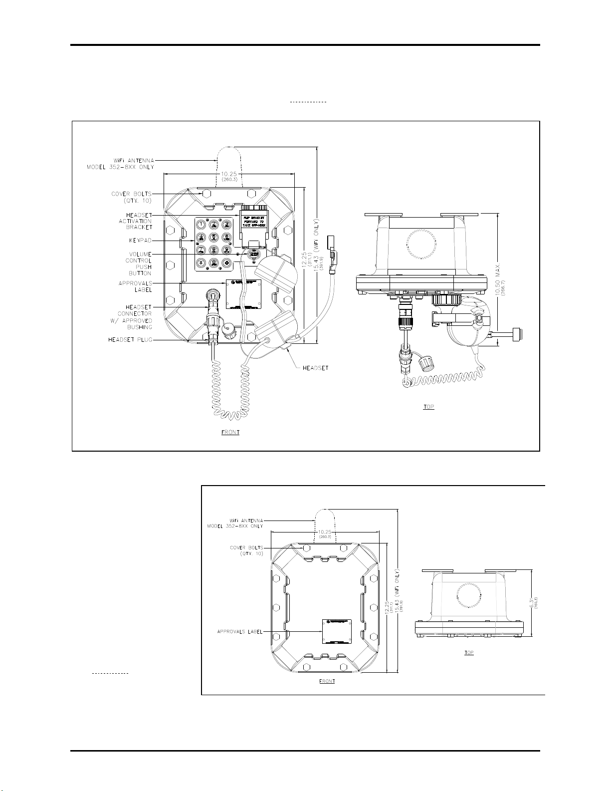
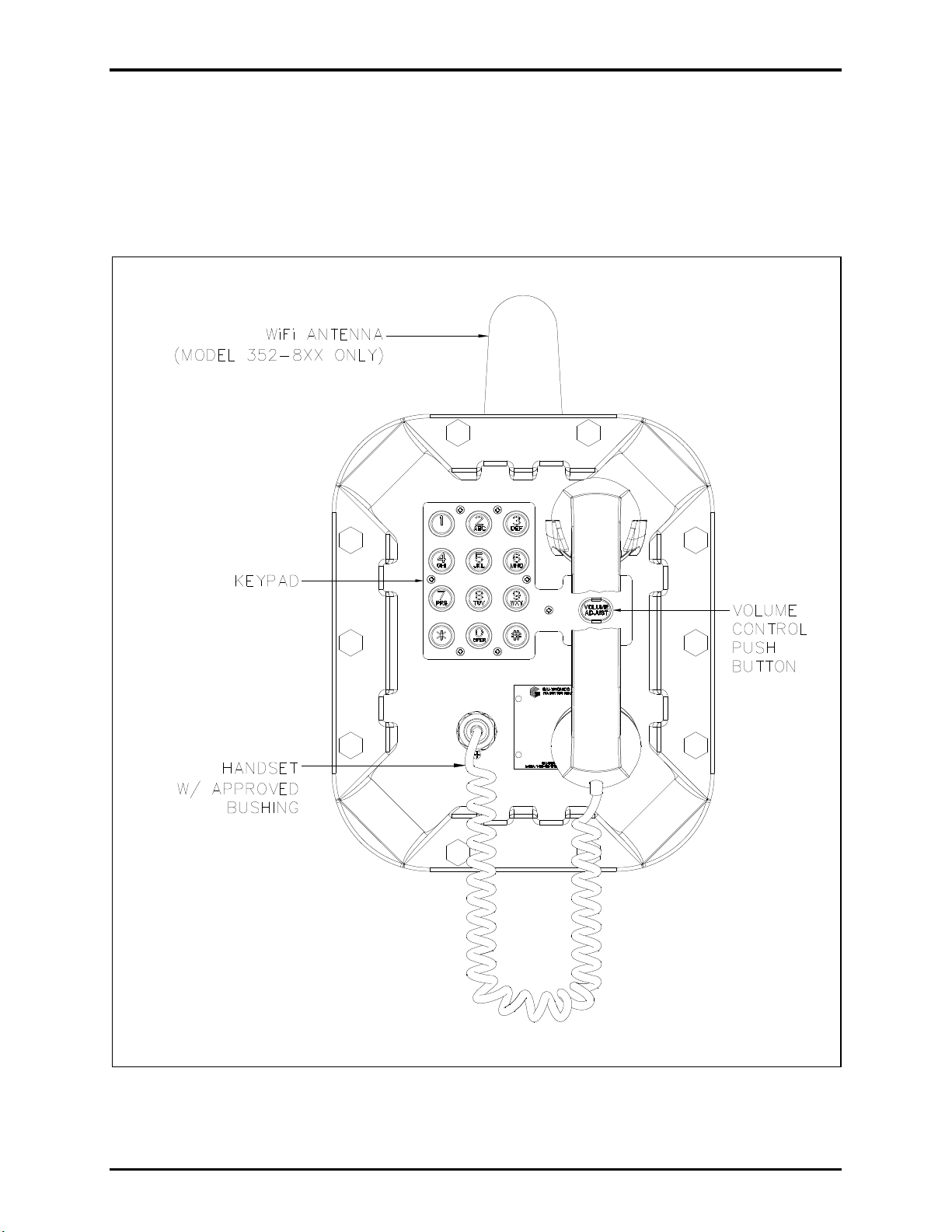
External.................................................................................................................................................4
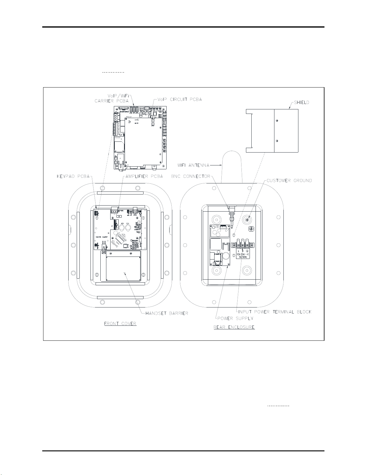
Internal..................................................................................................................................................6
Operation.........................................................................................................................................7
Handset Receiver Volume Control........................................................................................................7
Model 352-7x2 and 352-8x2 Handset Operation..................................................................................8
Model 352-7x3 and 352-8x3 Headset Operation ..................................................................................9
Headset Connection..............................................................................................................................9
Amplifier Paging (Multicast Broadcast).............................................................................................10
Installation ....................................................................................................................................10
Installation Guidelines..........................................................................................................................10
Mount the Telephone............................................................................................................................11
Cable Entries.........................................................................................................................................12
Front Cover Removal...........................................................................................................................12
Field Wiring...........................................................................................................................................13
Network Cable....................................................................................................................................15
Power ..................................................................................................................................................15
Auxiliary I/O.......................................................................................................................................15
USB port ................................................................................................................................................16
Front Cover Installation.......................................................................................................................16
Programming ................................................................................................................................17
First Time WiFi Interface Setup..........................................................................................................17
Reset WiFi Interface Configuration....................................................................................................20

Table of Contents Pub. 42004-486C
GAI-TRONICS 3030 KUTZTOWN RD. READING, PA 19605 USA
610-777-1374 ◼800-492-1212 ◼Fax: 610-796-5954
VISIT WWW.GAI-TRONICS.COM FOR PRODUCT LITERATURE AND MANUALS
VoIP Page Phone Setup........................................................................................................................20
VoIP Page Phone Initial Network Configuration ..............................................................................20
Alternate Configuration Methods.......................................................................................................21
Input Contacts.......................................................................................................................................21
Output Contacts....................................................................................................................................21
Maximum (Handset Receiver) Level Remote Control ......................................................................21
Maintenance..................................................................................................................................22
Status Indication...................................................................................................................................22
Power ..................................................................................................................................................22
Heartbeat.............................................................................................................................................22
Link.....................................................................................................................................................22
Speed................................................................................................................................................... 22
WiFi Activity (WiFi Units Only)........................................................................................................23
WiFi Ready (WiFi Units Only)...........................................................................................................23
WiFi Connected (WiFi Units Only)....................................................................................................23
VoIP Circuit PCBA Pushbuttons ........................................................................................................23
Reset....................................................................................................................................................23
Factory ................................................................................................................................................ 23
Monitoring and Reporting...................................................................................................................23
Service....................................................................................................................................................24
Troubleshooting....................................................................................................................................24
Reference Documentation ............................................................................................................24
Specifications ................................................................................................................................24
Power Requirements.............................................................................................................................24
VoIP Network........................................................................................................................................25
WiFi Network........................................................................................................................................25
Handset Audio.......................................................................................................................................25
Speaker Audio.......................................................................................................................................25
Environmental.......................................................................................................................................27
Mechanical.............................................................................................................................................27
Approvals.......................................................................................................................................27
User Instructions (USA)......................................................................................................................27

Pub. 42004-486C
GAI-TRONICS®
A HUBBELL COMPANY
Division 1 VoIP Page Phones
Wired & WiFi
GAI-TRONICS 3030 KUTZTOWN RD. READING, PA 19605 USA
610-777-1374 800-492-1212 Fax: 610-796-5954
VISIT WWW.GAI-TRONICS.COM FOR PRODUCT LITERATURE AND MANUALS
Confidentiality Notice
This manual is provided solely as an installation, operation, and maintenance guide and contains sensitive
business and technical information that is confidential and proprietary to GAI-Tronics. GAI-Tronics
retains all intellectual property and other rights in or to the information contained herein, and such
information may only be used in connection with the operation of your GAI-Tronics product or system.
This manual may not be disclosed in any form, in whole or in part, directly or indirectly, to any third
party.
General Information
GAI-Tronics’ Class 1 Division 1 VoIP page phones are
constructed of cast aluminum and are weatherproof and
corrosion resistant. The built-in, high-efficiency, Class
D paging amplifier provides up to 30 watts of speaker
output, allowing multicast broadcasting of
pages/announcements over speakers.
GAI-Tronics’ VoIP page phones are available in wired
and wireless versions with three model types: handset,
headset, and amplifier-only. Each model type has
several input power options (see Table 1).
Division 1 VoIP wired page phones connect to a 10/100
BaseT Ethernet network. Full power operation requires
an external ac or dc power source. PoE (Power-over-
Ethernet) models do not require additional power but
have limited speaker output.
WiFi models connect to a WLAN (wireless local area
network) meeting the IEEE 802.11 a/b/g/n standard. An
external ac or dc power source is required for operation.
These page phones also provide real-time alarm
reporting. This enables monitoring telephone activity to
address caller needs or maintenance issues immediately.
Configurable inputs and outputs are also available in all
models.
Figure 1. Mode 352-8xx Div. 1 VoIP WiFi
Page Phone

Pub. 42004-486C
Division 1 VoIP Page Phones—Wired & WiFi Page 2 of 27
P:\Standard IOMs - Current Release\42004 Instr. Manuals\42004-486C.docx
03/20
Table 1. Model Chart
Model
Description
Handset Models
352-712
Div. 1 VoIP AC Page Phone
352-722
Div. 1 VoIP DC Page Phone
352-732
Div. 1 VoIP PoE Page Phone
352-812
Div. 1 VoIP WiFi AC Page Phone
352-822
Div. 1 VoIP WiFi DC Page Phone
Headset Models
352-713
Div. 1 VoIP AC Page Phone
352-723
Div. 1 VoIP DC Page Phone
352-733
Div. 1 VoIP PoE Page Phone
352-813
Div. 1 VoIP WiFi AC Page Phone
352-823
Div. 1 VoIP WiFi DC Page Phone
Amplifier-Only Models
352-711
Div. 1 VoIP AC Page Phone
352-721
Div. 1 VoIP DC Page Phone
352-811
Div. 1 VoIP WiFi AC Page Phone
352-821
Div. 1 VoIP WiFi DC Page Phone
Features and Functions
GAI-Tronics VoIP telephones include the following features:
•SIP compatible (RFC3261)
•real-time alarm reporting via SNMP or syslog
•PoE (Power-over-Ethernet) compatible (Power Mode A, Class 0)
•configurable via web page or download
•four configurable auxiliary inputs
•two configurable dry-contact outputs

Pub. 42004-486C
Division 1 VoIP Page Phones—Wired & WiFi Page 3 of 27
P:\Standard IOMs - Current Release\42004 Instr. Manuals\42004-486C.docx
03/20
System Requirements and Limitations
VoIP
Connect two VoIP telephones in a peer-to-peer configuration without the need for a LAN. A 10/100
BaseT Ethernet network with SIP server is required for systems containing three or more VoIP
telephones. Conferences are limited by the customer’s LAN media capabilities and the services available
at each end point.
VoIP WiFi
Two telephones can communicate wirelessly in a peer-to-peer configuration without the need for a LAN
connection. However, a wireless access point connected to a 10/100 BaseT Ethernet network with SIP
server is required for systems containing three or more WiFi telephones (or a combination of WiFi and
hardwired VoIP telephones). Conferences are limited by the customer’s LAN media capabilities and the
services available at each end point.
Multicast Broadcasting
Each telephone can also receive multicast broadcasts. Multicast sends a single audio stream to multiple
end points simultaneously, achieving multi-point paging or public address functionality over IP.
Multicast requires the use of a SIP server or IP device that specifically supports multicast functionality
and each telephone must be configured (enabled) to receive multicast packets.
VoIP Subscriber Tips
New and existing subscriptions to an interconnected VoIP service provider should address the following
points:
•Provide accurate physical address information to the VoIP service provider to ensure that emergency
services can quickly be dispatched to the location.
•Be familiar with the VoIP service provider’s procedures for updating the address and promptly update
address information in the event of a change.
•Have a clear understanding of any limitations of the local 911 service.
•Be aware that VoIP telephone services may not work if the power is out or the Internet connection is
down. Consider installing a backup power supply, maintaining a traditional telephone line, or having
a wireless telephone as a backup.
•For questions about interconnected VoIP and 911, or VoIP in general, see
http://www.fcc.gov/cgb/consumerfacts/voip.html.

Pub. 42004-486C
Division 1 VoIP Page Phones—Wired & WiFi Page 4 of 27
P:\Standard IOMs - Current Release\42004 Instr. Manuals\42004-486C.docx
03/20
Hardware Description
External
Models 352-7x2 and 352-8x2 contain a handset with an approved cable gland, standard keypad, volume
control button, and applicable approval labeling. The handset rests on a cradle with a magnetic reed
switch to signal the off-hook condition. Ten cover mounting bolts, located around the perimeter of the
enclosure’s flange, seal the enclosure. The VoIP WiFi version includes a weatherproof WiFi antenna,
mounted on top of the enclosure (see Figure 2).
Figure 2. Model 352-7x2 and 352-8x2 Division 1 VoIP Page Phone with Handset

Pub. 42004-486C
Division 1 VoIP Page Phones—Wired & WiFi Page 5 of 27
P:\Standard IOMs - Current Release\42004 Instr. Manuals\42004-486C.docx
03/20
Models 352-7x3 and 352-8x3 are fitted with a removable headset and hook bracket. Activate the headset
by flipping the headset hook forward. The enclosure is sealed with ten cover mounting bolts, located
around the perimeter of the enclosure’s flange. The VoIP WiFi version includes a weatherproof WiFi
antenna, mounted to the top of the enclosure (see Figure 3).
Figure 3. Model 352-7x3 and 352-8x3 Division 1 VoIP Page Phone with Headset
Models 352-7x1 and
352-8x1 have no external
two-way communication
components. These
models are for amplifier
only usage. Ten cover
mounting bolts, located
around the perimeter of
the enclosure’s flange,
seal the enclosure The
VoIP WiFi version
includes a weatherproof
WiFi antenna, mounted
on top of the enclosure
(see Figure 4).
Figure 4. Model 352-7
x
1 and 352-8
x
1 WiFi Page Phone

Pub. 42004-486C
Division 1 VoIP Page Phones—Wired & WiFi Page 6 of 27
P:\Standard IOMs - Current Release\42004 Instr. Manuals\42004-486C.docx
03/20
Internal
Model 352-7xx VoIP Page Phones
The power supply, input power terminal block, and shield are mounted in the rear enclosure. The VoIP
carrier PCBA, VoIP circuit PCBA, amplifier PCBA, Keypad PCBA, and handset barrier are mounted to
the front cover. Amplifier-only versions do not include a keypad PCBA or handset barrier (see Figure 5).
Figure 5. Model 352-7xx Div. 1 VoIP Page Phone—Internal View

Pub. 42004-486C
Division 1 VoIP Page Phones—Wired & WiFi Page 7 of 27
P:\Standard IOMs - Current Release\42004 Instr. Manuals\42004-486C.docx
03/20
Model 352-8xx VoIP WiFi Page Phones
The power supply, input power terminal block, shield, and Div. 1 external antenna are mounted in the rear
enclosure. The VoIP/WiFi carrier PCBA, VoIP circuit PCBA, WiFi module, amplifier PCBA, keypad
PCBA, and handset barrier are mounted to the front cover. Amplifier-only versions do not include a
keypad or barrier (see Figure 6).
Figure 6. Model 352-8xx Div. 1 WiFi Page Phone
Operation
Handset Receiver Volume Control
A push-button switch on the front faceplate adjusts the handset receiver volume (see Figure 7). Press it
incrementally to decrease the volume from 20 dB, to 12 dB, to 0 dB, and back up to 20 dB, of the original
signal. The signal gain is automatically reset to 20 dB after the end of each call.

Pub. 42004-486C
Division 1 VoIP Page Phones—Wired & WiFi Page 8 of 27
P:\Standard IOMs - Current Release\42004 Instr. Manuals\42004-486C.docx
03/20
Model 352-7
x
2 and 352-8
x
2 Handset Operation
1. Lift the handset to place a call.
2. Adjust the handset receiver volume using the volume control push button, located on the front cover.
3. Dial the desired number.
4. Place the handset on hook after completion of the call.
Figure 7. WiFi Page Phone—Handset Version

Pub. 42004-486C
Division 1 VoIP Page Phones—Wired & WiFi Page 9 of 27
P:\Standard IOMs - Current Release\42004 Instr. Manuals\42004-486C.docx
03/20
Model 352-7
x
3 and 352-8
x
3 Headset Operation
Headset Connection
1. plug it into the flexible plug on the front of the telephone by removing the sealing cap from the
receptacle, aligning the connector pins, and screwing the two ends together (see Figure 8).
N
OTE
: The headset can be connected while the unit is powered.
Figure 8. On-hook Configuration—Div. 1 WiFi Page Phone—Headset Version
2. To place a call, remove the headset from the headset activation bracket and flip the headset bracket
forward from its pre-set position.
3. Adjust the headset volume using the volume control push button, located on the front cover.
4. Dial the desired number.
5. Flip the headset activation bracket to its vertical pre-set position to hang up. Place the headset on the
bracket after the completion of the call or disconnect the flexible receptacle and plug by unscrewing
the two ends and pulling them apart. Reattach the sealing cap to the end of the receptacle.
Figure 9. Off-hook Configuration—Div. 1 WiFi Page Phone—Headset Version

Pub. 42004-486C
Division 1 VoIP Page Phones—Wired & WiFi Page 10 of 27
P:\Standard IOMs - Current Release\42004 Instr. Manuals\42004-486C.docx
03/20
Amplifier Paging (Multicast Broadcast)
When making a multicast call, the SIP server or IP device will send paging requests to a specific IP
address and multiple telephones accept and play the subsequent audio. GAI-Tronics’VoIP telephones are
programmable for up to eight multicast addresses to permit the receipt of multicast broadcasts from
different sources or to enable zoning of broadcasts. Each multicast address can be assigned a priority (via
programming) to define the override order. A telephone with multicast enabled can still make and receive
normal calls. Normal calls are also assigned a priority level to define whether calls override multicasts or
vice versa.
Installation
Installation Guidelines
These enclosures must be installed by trained, qualified and competent personnel. Installation must
comply with state and national regulations, as well as safety practices for this type of equipment.
CAUTION
—Do not install this equipment in hazardous areas other than those indicated on
the approval listing in the Approvals section of this manual. Such installation
may cause a safety hazard and consequent injury or property damage.
The mounting location must be flat and provide proper clearance, rigidity and strength to support the
enclosure and all contained devices.
WARNING
—Securely fasten the enclosure to the mounting location, using 3/8-inch diameter
steel mounting bolts and washers, or washer head bolts.
WARNING
—Do not disconnect equipment while energized.
Ensure proper grounding to protective earthing.
WARNING
—The front cover is not hinged to the rear enclosure. Adequately support the front
cover while removing the cover bolts.
ATTENTION
—Installation must be performed by qualified personnel and only in accordance
with the National Electrical Code or applicable local codes.
Inspect and clean the machined flange flame joint surfaces of both the cover and box. Surfaces must be
smooth, free of nicks, scratches, dirt or any foreign particle build-up that would prevent a proper seal.
Surfaces must seat fully against each other to provide a proper explosion-proof joint. Clean surfaces by
wiping with a clean lint-free cloth.
Apply a light coat of Killark LUBG lubricant to flange surfaces and close the cover. Install and tighten
all cover bolts to 30 ft·lb. Make certain no cover bolts are omitted. Use only those bolts supplied with
the enclosure.
When installing any GAI-Tronics telephone equipment, please adhere to the following guidelines to
ensure the safety of all personnel:
•Electrostatic Discharge (ESD) Protection: Your telephone has an earth ground terminal provision.
Ensure that it is connected to ground in accordance with all local safety regulations and the National
Electrical Code (NEC). Grounding must be ensured for safe and stable communications. Do not use

Pub. 42004-486C
Division 1 VoIP Page Phones—Wired & WiFi Page 11 of 27
P:\Standard IOMs - Current Release\42004 Instr. Manuals\42004-486C.docx
03/20
long and coiled ground wires. Trim ground wires to the required length. Please note proper
grounding does not eliminate the need for lightning protection for the telephone or the telephone
system.
• NEVER install the telephone during a lightning storm.
• Install a category 5 data line lightning surge protector on any phone installed where the phone or
phone cable is at risk of being exposed to lightning strikes. Install the lightning arrestor as close to
the phone as possible in a non-hazardous environment. The lightning arrestor must not be installed
within the telephone enclosure.
• USE CAUTION when installing or modifying category 5 data lines.
Mount the Telephone
NOTE: The mounting surface must be able to support the 31-pound weight of the telephone.
Securely fasten the telephone enclosure to the mounting surface with 3/8-inch diameter steel mounting
bolts on all four mounting feet (see Figure 10).
• Stainless steel hardware is recommended in outdoor applications.
• The suggested mounting height is 48 inches to the bottom of the enclosure.
NOTE: Refer to the Killark Installation, Operation, and Maintenance data sheet for the Killark Part. No.
EXB-684 N34 base enclosure (enclosed with the unit) for additional information.
Figure 10. Model 352 Series Division 1 VoIP Page Phone Enclosure Mounting Detail

Pub. 42004-486C
Division 1 VoIP Page Phones—Wired & WiFi Page 12 of 27
P:\Standard IOMs - Current Release\42004 Instr. Manuals\42004-486C.docx
03/20
Cable Entries
• Seal all unused openings with proper fittings per local standards.
• Use field wiring suitable for the ambient temperature.
• Conduit NPT plugs (blanking elements) must be explosion-proof with a Type 4X rating (see Figure
11).
Figure 11. Model 352-7xx and 352-8xx Series VoIP/WiFi Conduit Entries
Front Cover Removal
WARNING —The front cover is not hinged to the rear enclosure. Adequately support the
cover while removing the cover bolts.
1. Remove the ten cover bolts from the enclosure flange while supporting the front cover.
2. Pull the front cover far enough away to expose the internal connections.
3. Flip the front cover 180º to the left and attach the front cover to the rear enclosure using the top left
bolt hole.
4. Rotate the cover approximately 10º from vertical and place a second bolt in the bottom left rear
enclosure hole.
• Allow the cover to rotate against the bottom bolt.
• Hand-tighten both bolts to secure.
• Do not over tighten.
CAUTION —Do not scratch or nick the flanges of the front cover or rear enclosure.

Pub. 42004-486C
Division 1 VoIP Page Phones—Wired & WiFi Page 13 of 27
P:\Standard IOMs - Current Release\42004 Instr. Manuals\42004-486C.docx
03/20
Figure 12. Installation and Maintenance Configuration
Field Wiring
Table 2. Recommended Cable
Cable Use Size
LAN Category 5 or Category 5e UTP cable with an RJ45 connector
Power Two-conductor, No. 18 AWG is typical
Inputs Two-conductor, No. 22 AWG is typical
Output contacts Two-conductor, No. 18 AWG is typical
Speaker Two or three-conductor, No. 18 AWG is typical
1. Wired versions: Plug the incoming Category 5 network cable into the RJ45 jack, located on the
underside of the VoIP PCBA (see Figure 13).
2. ac and dc powered models:
1. Remove the two screws from the power supply cover located in the rear enclosure and remove the
power supply cover.

Pub. 42004-486C
Division 1 VoIP Page Phones—Wired & WiFi Page 14 of 27
P:\Standard IOMs - Current Release\42004 Instr. Manuals\42004-486C.docx
03/20
2. Connect the incoming power conductors to the 3-point terminal block in the rear enclosure (see
the Local Power section).
3. Reattach the power supply cover using the two screws previously removed from the cover.
3. Route the speaker cable along the left side of the power supply to the speaker plug, P4, located on the
amplifier PCBA, on the front cover.
4. Terminate the speaker connection wires per the PCBA silk screen text (see Figure 13).
5. Install all additional connections as directed in the following subsections (see Table 2 and Figure 13).
Figure 13. Internal PCBA Connections

Pub. 42004-486C
Division 1 VoIP Page Phones—Wired & WiFi Page 15 of 27
P:\Standard IOMs - Current Release\42004 Instr. Manuals\42004-486C.docx
03/20
Network Cable
Connect a Category 5 or better UTP cable with an RJ45 connector between the LAN and the VoIP PCBA
(see Figure 13). The Ethernet jack is located on the underside of the VoIP PCBA.
Power
PoE (Power-over-Ethernet)
Connect power to the system as indicated in the PoE equipment manual. (Power Mode A, Class 0)
Local Power
Connect ac or dc power to the unit’s power termination block located in the rear enclosure (see Figure
14).
Figure 14. AC and DC Input Power Terminal Block Labels
Auxiliary I/O
Inputs
The page-phones have four auxiliary inputs for customer use:
1. Terminate the inputs to terminal block P12 (see ).
2. Connect each input between the desired input (INPUT 1–4) and common (COM) on terminal block
P12. Refer to the Pub. 42004-548 for programming instructions for these inputs (see the .
Table 3. Auxiliary Inputs—P12
Pin Label Function
1 IN4 Input 4
2 COM Common
3 IN3 Input 3
4 COM Common
5 IN2 Input 2
6 COM Common
7 IN1 Input 1
8 COM Common
Inputs have an internal pull-up resistor that is 3.3 V dc tolerant.

Pub. 42004-486C
Division 1 VoIP Page Phones—Wired & WiFi Page 16 of 27
P:\Standard IOMs - Current Release\42004 Instr. Manuals\42004-486C.docx
03/20
Outputs
Two outputs have been provided for customer use. Terminations for these outputs are provided on
connector P10.
Table 4. Output Contacts—P10
Pin
Label
Description
1
C1
Common Output 1
2
NO1
Normally Open Output 1
3
C2
Common Output 2
4
NO2
Normally Open Output 2
Relay capacity is 5 A @ 30 V ac/V dc.
USB port
The USB port is for GAI-Tronics service personnel only. Make no connection to this port.
Front Cover Installation
After all adjustments are complete:
1. Inspect and clean the machined flange joint surfaces of both the cover and box.
•Surfaces must be smooth, free of nicks, scratches, dirt, or any foreign particle build-up that may
prevent a proper seal.
•Surfaces must seat fully against each other to provide a proper explosion-proof joint.
2. Clean surfaces by wiping with a clean lint-free cloth.
3. Apply a light coat of Killark LUBG lubricant to flange surfaces.
4. Close the cover.
5. Install and tighten all cover bolts to 30 ft·lb.
•Do not omit any cover bolts.
•Use only those bolts supplied with the enclosure.
NOTE:Refer to the Killark Installation, Operation, and Maintenance Data Sheet, Killark Part. No. EXB-
684 N34 base enclosure (enclosed with the unit) for additional information.

Pub. 42004-486C
Division 1 VoIP Page Phones—Wired & WiFi Page 17 of 27
P:\Standard IOMs - Current Release\42004 Instr. Manuals\42004-486C.docx
03/20
Programming
The installer should ensure that the network is configured to allow VoIP communications (using the SIP
protocol) between the desired locations before attempting to configure GAI-Tronics VoIP Telephones.
First Time WiFi Interface Setup
Setup the WiFi interface to configure the telephone’s WLAN connection security:
1. Power on the telephone by connecting 24 to 48 V dc to terminal block P5.
The factory default configuration of the VoIP WiFi telephone’s interface is an access point on a
network named (SSID) HF-A11_AP.
2. Connect to the HF-A11_AP network using a PC/laptop with a wireless adapter.
The yellow LED on the telephone’s WiFi interface should be ON when the PC is connected to the
HFA11_AP network.
3. Open a web browser on the PC and enter 10.10.100.254 into the address field and press ENTER.
NOTE:Verify that the PC’s wireless network adapter is set to DCHP (Obtain an IP address
automatically) to connect to the HF-A11_AP access point.
The HF-A11_AP WiFi log in window opens.
4. Enter admin for both the user and password, and log in.
The WORKING MODE CONFIGURATION web page opens:
Figure 15. WiFi Interface Working Mode Configuration Web page
5. Select STAMODE then click the APPLY button.
The webpage will show Set Successfully, Restart to use new setting.
6. Restart to use the new setting, and then click on the STA Interface Setting selection.
The STA INTERFACE SETTING web page opens:

Pub. 42004-486C
Division 1 VoIP Page Phones—Wired & WiFi Page 18 of 27
P:\Standard IOMs - Current Release\42004 Instr. Manuals\42004-486C.docx
03/20
Figure 16. WiFi Interface STA Interface Setting Web page
7. Click the SEARCH button, to the right of in the AP’s SSID field, to find the WiFi network that the
VoIP telephone will operate in.
The Site Survey webpage opens, showing all available networks.
Figure 17. WiFi Interface Site Survey Web page
8. Select the desired network and click the APPLY button.
A reminder window to enter the WEP key or pass phrase pops up.
9. Click the OK button.
10. Enter the WEP Key or Pass Phrase for the selected network and click the APPLY button.
The AP’s SSID, security mode, and encryption type fields will be filled in when the STA interface
setting webpage opens again.
NOTE:Manually enter the AP’s SSID, security mode, encryption type, and WEP key or pass phrase
if the VoIP telephone is not within the range of the wireless network that it is being
configured to operate in.
This manual suits for next models
17
Table of contents
Other Hubbell IP Phone manuals

Hubbell
Hubbell GAI-TRONICS Auteldac 6 User manual

Hubbell
Hubbell GAI-Tronics RED ALERT 397-700CB User manual

Hubbell
Hubbell GAI-TRONICS Titan Series User manual

Hubbell
Hubbell GAI-Tronics 1193 User manual

Hubbell
Hubbell GAI-Tronics Division 2 351-71 User manual

Hubbell
Hubbell GAI-Tronics Clean Phone 1193 User manual

Hubbell
Hubbell GAI-TRONICS 210-700BH User manual

Hubbell
Hubbell GAI-TRONICS 210-712 User manual

Hubbell
Hubbell GAI-Tronics Division 1 352-701 User manual

Hubbell
Hubbell GAI-TRONICS 210-702BH User manual