manuals.online logo
Brands
  1. Home
  2. •
  3. Brands
  4. •
  5. Hubbell
  6. •
  7. Lighting Equipment
  8. •
  9. Hubbell DUAL LITE LN4X Series Owner's manual

Hubbell DUAL LITE LN4X Series Owner's manual

TROUBLE SHOOTING
•“EXIT” legend does not illuminate
• Checkwiringconnections.
•Emergency circuit does not work
• Batteriesareshippedunchargedanddisconnected.Connectpowerpackleadsandchargebeforetesting.
 • Makesurechargerboardisproperlyseated.
 • Checkwiringconnections.
TESTING
SignsshouldbetestedandmaintainedinaccordancewithNationalElectricalCodeandNFPA101LifeSafetyCoderequirements.Itisrecommendedthat
emergencyexitsignsbetestedfor30secondsonceamonthandfor90minutesonceayear.
REPLACING A BATTERY PACK
De-energizetheACpowersupplytotheexitsign;removetheclearcover.Removethewhitetrimplateandtheexitsignface.Disconnectthe2-pinbattery
packconnectorfromthechargerboard.Removethebatterypackfromthecompartment.Installanewbatterypackwiththecorrectpartnumberintothe
compartment,andpluginthe2-pinconnectortothechargerboard.Reinstalltheexitsignface,whitetrimplateandsecuretheclearcover.EnergizeACpower
totheexitsign.Allowthenewbatterypacktofullycharge,andpressthe“TEST”buttontoverifyoperation.
RECYCLING INFORMATION
Allthermoplasticpartsarerecyclable.Allcartonscontainrecycledmaterials.Pleaserecycleresponsibly.
NOTICE:
Emergency model exit signs contain rechargeable nickel-cadmium batteries which must be recycled or disposed of properly.
LN4X Series
LED Exit Sign Listed For Damp And Wet Locations
AC Non-Emergency Models Are UL Type 4X Rated
Installation, Operation and Maintainance Instructions
Hubbell Lighting, Inc. Life Safety Products • www.dual-lite.com
Copyright©HubbellLighting,Inc.,AllRightsReserved•Specicationssubjecttochangewithoutnotice.•PrintedinU.S.A.
93029236A 6/10
IMPORTANT SAFEGUARDS
Whenusingelectricalequipment,basicsafetyprecautionsshouldalwaysbefollowedincludingthefollowing.
READ AND FOLLOW ALL SAFETY INSTRUCTIONS
 1.Donotletpowersupplycordstouchhotsurfaces.
 2.Donotmountneargasorelectricheaters.
 3.Equipmentshouldbemountedinlocationsandatheightswhereitwillnotreadilybesubjecttotampering
  byunauthorizedpersonnel.
 4.Theuseofaccessoryequipmentnotauthorizedbythemanufacturermaycauseanunsafecondition.
 5.Donotusethisequipmentforotherthanitsintendedpurpose.
 6.Servicingofthisequipmentshouldbeperformedbyqualiedservicepersonnel.
 7.Testcycling:theLifeSafetyCode(NFPA101)requirestestingofemergencyexitsignsonceamonthfora
  minimumof30secondsandonceayearforaminimumof90minutes.
INSTALLER:
•SEE UNIT LABEL FOR ADDITIONAL MODEL SPECIFICATIONS
•SAVE THESE INSTRUCTIONS FOR USE BY OWNER/OCCUPANT
WARNING–ThisproductcontainschemicalsknowntotheStateofCaliforniatocausecancer,birthdefectsand/orother
reproductiveharm.Thoroughlywashhandsafterinstalling,handling,cleaning,orotherwisetouchingthisproduct.
93033371
OPERATION
“ACON”LEDisiluminatedwhenACpowerispresent.
NOTE:AllmodelsaresuppliedwithanACLockoutcircuit,whichpreventsthe“EXIT”legendfromilluminatingwhenthebatteryisconnectedandnoACpower
ispresent.
NOTE:AllmodelsaresuppliedwithaLowVoltageDisconnectcircuit,whichpreventsdamagetothebatteryfromdeepdischargeduringprolonged
emergencyoperation.
NOTE:Batteriesareoftenshippedinadischargedstate–thisisnormal.Thebatterywillrequirecharging.Allowseveralhoursofchargebeforetestingtheunit.
ModelsWithSPECTRON®Self-Testing/Self-DiagnosticCircuitry
ModelsequippedwiththeSpectronself-testing/self-diagnosticelectronicssystemprovide:
■VisualindicationofACpowerstatus ■Visualindicationofself-diagnostictestcycle
 —Visualindicationofanyunitmalfunctionsincluding—
■Battery fault ■Transfer fault ■Charger fault ■Emergency Lamp fault
Spectron equipped units also include:
Brownout protection: unit will automatically transfer to emergency operation upon detection of low AC power (approximately 80% of nominal line).
Time Delay Retransfer: upon return of normal AC power, unit will remain in the emergency mode for an additional 15 minutes to allow AC power to stabilize.
LEDStatusIndicator
AbicolorLED(green/red)isprovidedonthecontrolpanelofallmodels
equippedwiththeSpectronoption.
RedStatusIndicatorCode Description
OneblinkON/pause Batterynotconnected
TwoblinksON/pause Batteryfault
ThreeblinksON/pause Chargerfault
FourblinksON/pause Transfercircuitfault
FiveblinksON/pause EmergencyLampfault
AutomaticTests
Theunitwillautomaticallyinitiateaself-test/self-diag-
nosticcyclebasedonthefollowingtable:
TestingPeriod DurationofTest
Onceamonth 1minute
Onceevery6months Alternating:
30minutesor60minutes
ManualTests
Usingtheunittestswitch,userscaninitiatedifferent
durationtestcyclesbasedonthefollowingtable:
InitiatingAction TestCycle
Presstestswitchonce 1minute
Presstestswitchtwice 90minutes
Pressingthetestswitchatanytimeafteratestcyclehas
beguncancelstheremainderofthetestandreturnsthe
unittonormaloperation.
RedServiceAlertIndicator
Undernormaloperatingconditions,theredServiceAlertIndicatorwillremain“off”.
IntheeventtheSpectroncontrollerdetectsamalfunction,theredServiceAlert
Indicatorwillblinkata1Hz.rate,basedonthefollowingtable:
GreenOperatingStatusIndicator
ThegreenOperatingStatusIndicatorservesasbothanACpowerandaself-test
indicator.Duringnormaloperation,thegreenOperatingStatusIndicatorwillbe
illuminated,indicatingthepresenceofACpower.Duringallautomaticormanual
self-testcycles,thegreenOperatingStatusIndicatorwillblinkata1Hz.rate.
MAINTENANCE
1300681
1300682
1300684
1300685
93029025
93029029
93029235
93029327
Fig. 3
INSTALLATION INSTRUCTIONS
IMPORTANT:Thisexitsignmaybeequippedwithoneormoreoptions.
Checkmodelnumbersufxforoptiondesignation.Optionconnection
wiresmustberunbeforeexitsignface,whitetrimplateandclearcover
areinstalled.
FIRE ALARM PANEL (-FAP) OPTION
FAPoptionconnectsto24voltACorDC(purplewires).
FlashRate:.5secondson,.5secondsoff.DutyCycle:50%.
DC REMOTE (-DC) OPTION
DCRemoteoptionconnectsto6-24voltDC[yellow(–),blue(+)].
FLASHER MODULE (-FM) OPTION
FlashRate:.5secondson,.5secondsoff.DutyCycle:50%
Connectoptionwires(-FAP
or-DC)togreyconnectoron
optionboard.
Routewiresthrough
transformercompartmentand
outbackplate.
93029029
2. Thewhitetrimplatesurroundingthe
exitsignfaceisheldinplaceby“hook
andloop”velcro,locatedonthe
undersideofthetrimplate.Remove
thetrimplatebycarefullylifting
straightuptodisengagethevelcro.
4. Drilltheappropriatesize
holeintheenclosurefor
conduitentrance.Fig. 2
showstherecommended
locations.
1300681
3. Removetheexitsignand
mountingbracketfrom
theenclosurebefore
proceedingtoStep4.
5. ConnectappropriateULListedhub(s)tothe
conduit,andconnecttotheenclosure.Route
buildingutilityconductorsthroughconduitand
intoenclosure.
1300681
6. Reinstallexitsignmountingbracketandexit
sign.Removeexitsignfrontfacefromhousing
beforeproceedingtoStep7.
WIRING DIAGRAM
120/277VAC
AC ONLY, EMERGENCY MODELS
1. Loosenthefourslotted
coverscrewsandremove
theclearcover.
 (Typical,fourlocations)
Fig.1
Fig.2
7. MakeallconnectionstobuildingutilityAC
conductorsusingcolorcodedleadsprovided.
 SeeFig.3andFig4.forappropriatewiring
diagrams.
Fig. 4
WIRING DIAGRAM
120/277VAC
DUAL CIRCUIT (-2C Option) MODELS
8. Foremergencymodels,connect
thebatteryasshowninFig.5.
93029025
Dual-circuittransformer
secondarywiresconnect
toinputconnector
onoptionboard. Connectdual-circuitprimarytransformer
wirestoutilitysource.
120VAC-connectblackandwhiteleads.
277VAC-connectredandwhiteleads.
Fig. 5
EMERGENCY MODEL
BATTERY CONNECTION
Chargerboardandbattery
pack.(Emergencymodelsonly).
Foremergencymodels,plug2-pin
batteryconnectorintoPCboard.
9. Snap-inappropriatechevronarrowblank-outsinexitsignfrontface,
 ifrequired.Reassembleexitsignfacetohousing.Rinstallthewhite
trimplate(pressdowntoengagethefasteningstrips).Securethe
clearcovertotheenclosure.
10.EnergizetheACpowertotheexitsign.
 NOTE:Foremergencymodels,allowthebatterytofullycharge
 beforetesting.
93029235
1300685
1300685

Other Hubbell Lighting Equipment manuals

Hubbell G040 Instruction Manual

Hubbell

Hubbell G040 Instruction Manual

Hubbell Dual-Lite EV4D-02WAL Series Manual

Hubbell

Hubbell Dual-Lite EV4D-02WAL Series Manual

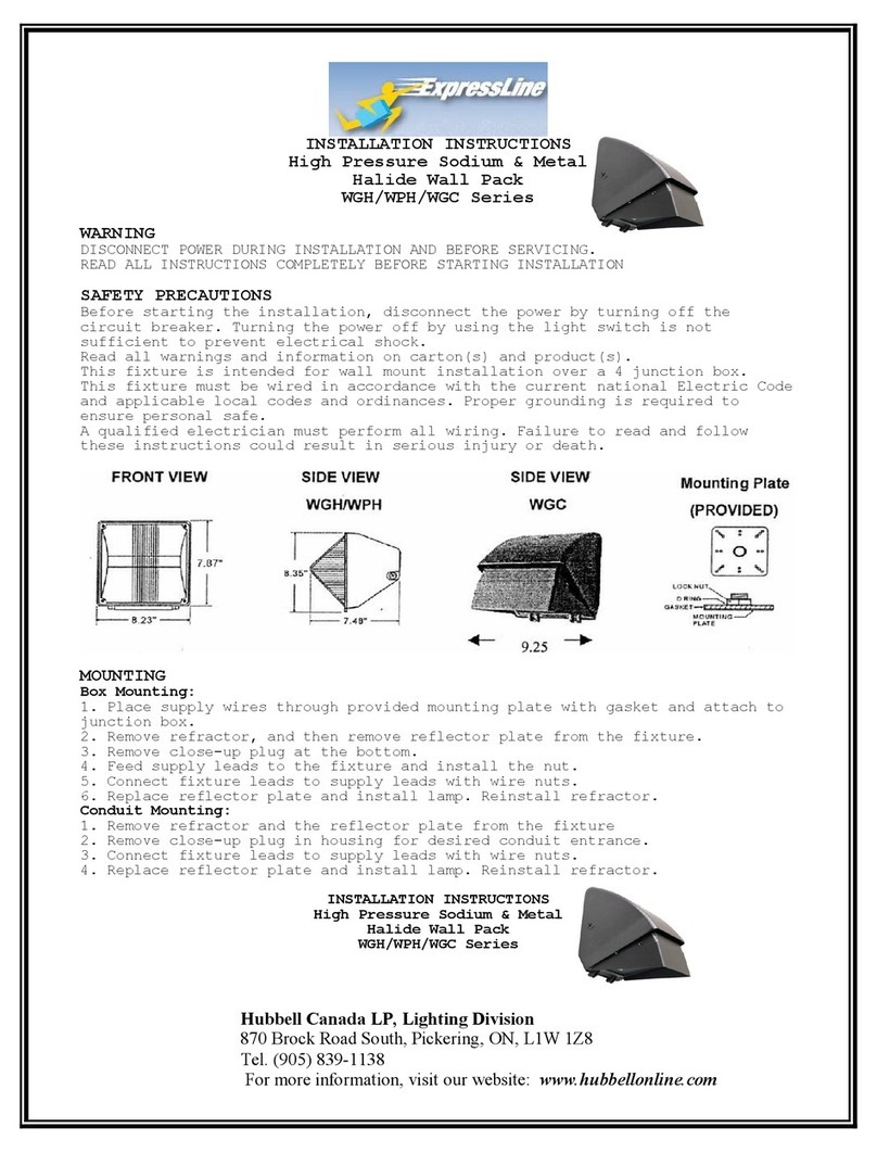
Hubbell WPH Series User manual

Hubbell

Hubbell WPH Series User manual

Hubbell DUAL LITE PG Series User manual

Hubbell

Hubbell DUAL LITE PG Series User manual

Hubbell Prescolite LBSLEDA User manual

Hubbell

Hubbell Prescolite LBSLEDA User manual

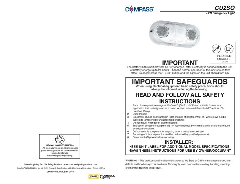
Hubbell Compass CU2SO User manual

Hubbell

Hubbell Compass CU2SO User manual

Hubbell Laredo LMC User manual

Hubbell

Hubbell Laredo LMC User manual

Hubbell PRS User manual

Hubbell

Hubbell PRS User manual

Hubbell Dual Lite EV Series Manual

Hubbell

Hubbell Dual Lite EV Series Manual

Hubbell DUAL LITE EVE Series User manual

Hubbell

Hubbell DUAL LITE EVE Series User manual

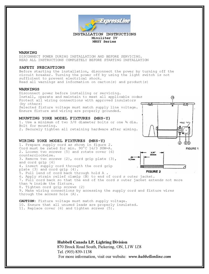
Hubbell ExpressLine Miniliter IV MHSY Series User manual

Hubbell

Hubbell ExpressLine Miniliter IV MHSY Series User manual

Hubbell Kim Lighting Lightvault LTV59 User manual

Hubbell

Hubbell Kim Lighting Lightvault LTV59 User manual

Hubbell Litecontrol 22L Series User manual

Hubbell

Hubbell Litecontrol 22L Series User manual

Hubbell KILLARK VSQ Series Owner's manual

Hubbell

Hubbell KILLARK VSQ Series Owner's manual

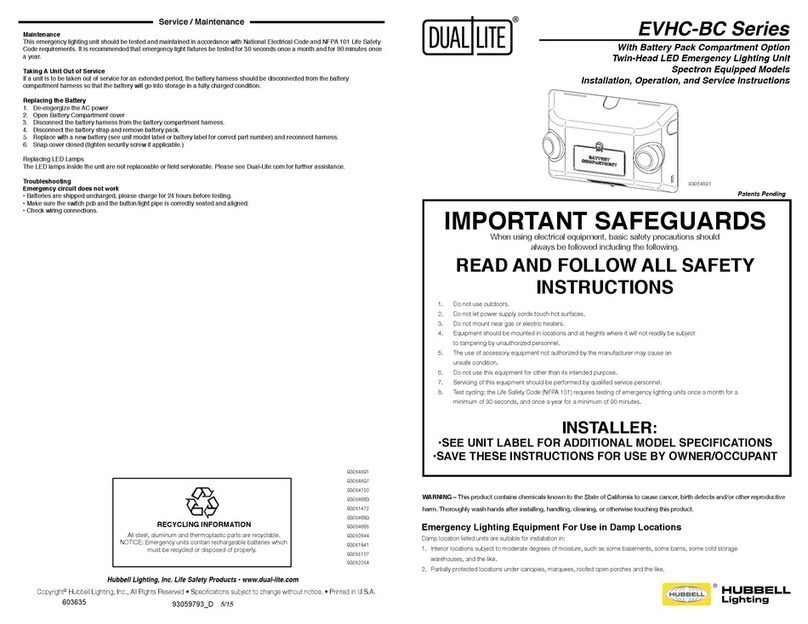
Hubbell Dual-Lite EVHC-BC Series Manual

Hubbell

Hubbell Dual-Lite EVHC-BC Series Manual

Hubbell VAPORTITE VBGL Series User manual

Hubbell

Hubbell VAPORTITE VBGL Series User manual

Hubbell NXP2 Series User manual

Hubbell

Hubbell NXP2 Series User manual

Hubbell KIM LIGHTING VRB1 User manual

Hubbell

Hubbell KIM LIGHTING VRB1 User manual

Hubbell LITEFRAME LC4 User manual

Hubbell

Hubbell LITEFRAME LC4 User manual

Hubbell Dual Lite CVEC15 User manual

Hubbell

Hubbell Dual Lite CVEC15 User manual

Hubbell M-7679 R-PAC User manual

Hubbell

Hubbell M-7679 R-PAC User manual

Hubbell Dual Lite EZ-2R Series Manual

Hubbell

Hubbell Dual Lite EZ-2R Series Manual

Hubbell ALFW-6LU-5KBZ Series User manual

Hubbell

Hubbell ALFW-6LU-5KBZ Series User manual

Hubbell Laredo User manual

Hubbell

Hubbell Laredo User manual

Popular Lighting Equipment manuals by other brands

Secom INNVICTUM 6400 Installation and assembly instructions

Secom

Secom INNVICTUM 6400 Installation and assembly instructions

RSA Lighting COMBOLIGHT LV850MH Specification sheet

RSA Lighting

RSA Lighting COMBOLIGHT LV850MH Specification sheet

Outwell ORION LUX instruction manual

Outwell

Outwell ORION LUX instruction manual

Robus HARBOUR RHA70406FTV2-24 instructions

Robus

Robus HARBOUR RHA70406FTV2-24 instructions

Chauvet LED Mushroom user guide

Chauvet

Chauvet LED Mushroom user guide

Elation SATURA SPOT LED PRO user manual

Elation

Elation SATURA SPOT LED PRO user manual

EuroLite LED PST-10 user manual

EuroLite

EuroLite LED PST-10 user manual

Irradiant SRL-6056S user manual

Irradiant

Irradiant SRL-6056S user manual

PLG ASY R user manual

PLG

PLG ASY R user manual

SSI METEORLITE installation instructions

SSI

SSI METEORLITE installation instructions

ADJ FOCUS PROFILE user manual

ADJ

ADJ FOCUS PROFILE user manual

GAME OF BRICKS Real Madrid Santiago Bernabeu Stadium 10299 instruction manual

GAME OF BRICKS

GAME OF BRICKS Real Madrid Santiago Bernabeu Stadium 10299 instruction manual

ADB Safegate RELIANCE Shallow Base user manual

ADB Safegate

ADB Safegate RELIANCE Shallow Base user manual

Lightolier MIC100 specification

Lightolier

Lightolier MIC100 specification

Monster SMART ILLUMINESSENCE DIGIT Design guide

Monster

Monster SMART ILLUMINESSENCE DIGIT Design guide

Z-CAM ZOLAR Vega 30C user manual

Z-CAM

Z-CAM ZOLAR Vega 30C user manual

JB Systems Radiant Operation manual

JB Systems

JB Systems Radiant Operation manual

Eaton CEAG Exit Cube 33822 LED CGLine+ Mounting and operating instructions

Eaton

Eaton CEAG Exit Cube 33822 LED CGLine+ Mounting and operating instructions

manuals.online logo
manuals.online logoBrands
  • About & Mission
  • Contact us
  • Privacy Policy
  • Terms and Conditions

Copyright 2025 Manuals.Online. All Rights Reserved.