This unit is designed to be mounted on a wall or ceiling. Provide standard units witha single unswitched supply from
a 120VAC, 240VAC, or 277VAC branch circuit used for normal lightning in the area to be protected. For Spectron®
self-testing/self-diagnostic units, provide unit with 120VAC or 277VAC branch circuit.
The EV unit is equipped with intelligent wiring. Connect the black wire from the unit to the hot building wire
(120-277VAC) and the white wire to the neutral building wire.
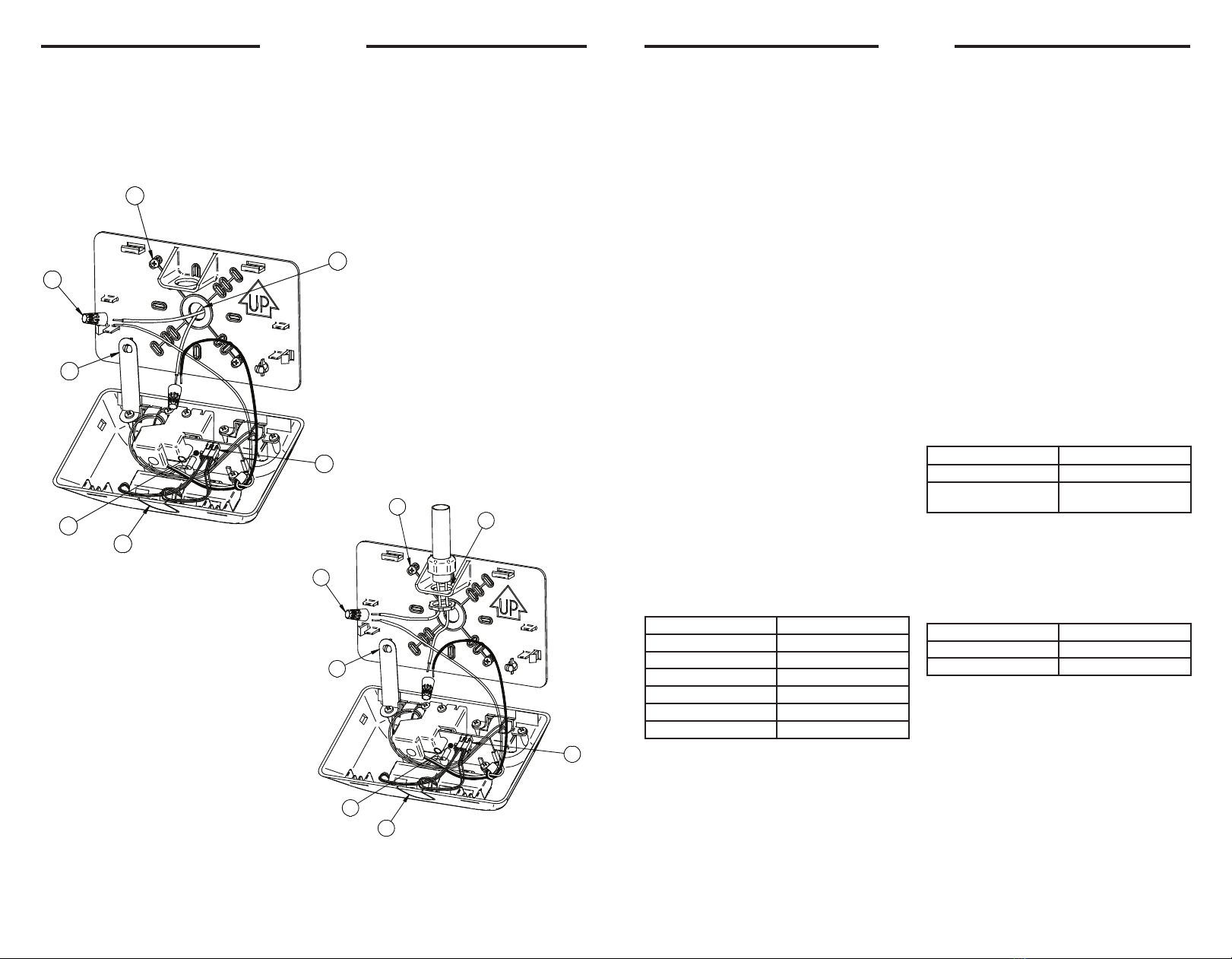
Wall or Ceiling Mount - Back Power Feed
1. Remove appropriate KO’s in backplate to
mount backplate to junction box.
2. Remove center KO from backplate and feed
suppply leads through.
3. Secure backplate to junction box.
4. To help with wiring, attach cover to backplate
with provided plastic hinge
5. Connect wires from the unit to the building
leads and secure with wire nuts.
6. Connect battery lead to circuit board header
as shown.
“AC ON” LED is illuminated when AC power is present.
NOTE: All models are supplied with an AC Lockout circuit, which prevents the emergency lights from illuminating
when the battery is connected and no AC power is present.
NOTE: All models are supplied with a Low Voltage Disconnect circuit, which prevents damage to the battery from
deep discharge during prolonged emergency operation.
NOTE: Batteries are often shipped in a discharged state - this is normal. The battery will require charging.Allow 24
hours of charging before testing the unit.
Models with SPECTRON® Self-Testing/Self-Diagnostic Circuitry
Models Equipped with the Spectron® self-testing/self-diagnostic electronics system provide:
•Visual indicatiioin ofAC power status •Visual indicatiion of self-diagnostic test status and results
--Visual indication of any unit malfunction include--
• Battery Disconnected • Battery Fault • Charger Fault • LED Driver Fault • Lamp Fault
Spectron equipped units also include:
Brownout protection: unit wll automatically transfer to emergency operation upon detection of low AC power
(approximately 80% of nominal line)
Dime Delay Retransfer: upon return of normal AC power, unit will remain in emergency mode for an additional 15
minutes to allow AC power to stabalize.
** **
The Spectron® optioned EV4DI requires a load learn process at
installation. Press and hold the test button for more than 5 seconds
to initiate the load learn.
LED Status Indicator
A bicolor LED (green/red) is provided on the control
panel of all models equipped with the Spectron® option.
Green Operating Status LED:
The green Operating Status LED serves as both
an AC power and self-test indicator. During normal
operation, the green Operating Status LED will be
illuminated, indicating the presence of AC power. During
all automatic or manual self-test cycles, the green
Operating Status LED will blink twice every second.
Red Service Alert LED:
Under normal operating conditions, the red Service Alert
LED indicator will remain off. If the Spectron® controller
detects a malfunction, the red Service Alert LED will
blink in the pattern listed in the following table:
Red Status LED Code Description
One Blink: ON/Pause Battery Disconnected
Two Blinks: ON/Pause Battery Fault
Three Blinks: ON/Pause Charger Fault
Four Blinks: ON/Pause LED Driver fault
Five Blinks: ON/Pause Lamp Fault
Red/Green Alternating Load Learn in Process
Automatic Tests.
The unit will automatically initiate a self-test/self-
diagnostic cycle based on the following table:
Testing Period Duration of Test
Once a month 1 minute
Once every 6 months Alternating: 30 minutes or
60 minutes
Note: After clearing a 5 blink lamp fault by initiating
a load learn test, a 60 second manual test must be
initiated.
Manual Tests
Using the unit test switch, users can initiate different
duration test cycles based on the following table:
Initiating Action Test Cycle
Press test switch once 1 minute
Press test switch twice 90 minutes
Pressing the test switch any time after a 90 min. test
cycle has begun cancels the remainder of the 90 min.
test and returns the unit to normal operation.
Wall Mount - Surface Wiring (Top Power Feed Only)
1. Remove appropriate KO’s in backplate to mount
backplate to junction box.
2. Feed wires through and secure conduit to backplate
3. Remove the breakout on top of the housing.
4. To help with wiring, attach cover to backplate with
provided plastic hinge.
5. Connect wires form the unit to the building leads and
scure with wire nuts.
6. Connect bettery lead to circuit board header as
shown.
INSTALLATION Operation
12
1
B
A
B
2
A
This document contains confidential and proprietary information of Dual Lite.
Receipt or possession of this document does not convey any rights to
reproduce or disclose its contents, or to make, use , or sell anything it may
disclose. Reproduction, disclosure, or use of the document or its contents,
without the specific written authorization of Dual Lite, may violate the
intellectual property rights of Dual Lite.
CRITICAL DIMENSIONS
UNSPECIFED TOLERANCES: INCHES
X.X=
0.02 X.XX=
0.01 X.XXX=
0.005
FRACTIONS=
1/32 ANGULAR TOLERANCE=
.5
REV.
PART NO.FINISH:MATERIAL:
THIRD ANGLE PROJECTION
DRAWN:
DO NOT SCALE PRINT
CONFORMS TO ASME Y14.5M
DIMENSIONS IN [ ] IN MM
DIMENSIONS IN INCHES
CHECKED BY:
ENGINEERING:
CATALOG NO. SCALE
A
SIZE DRAWING NO.
SHT 1
1 SHTS
------
93099188
93099188
A
ILL-INST EV UNIT -02WAL INST1
JEB 6/28/2018
JEB 06/28/18
EC 171030003
JEB 06/28/18
1:2
5
4
2
1
6
3
7
12
1
B
A
B
2
A
This document contains confidential and proprietary information of Dual Lite.
Receipt or possession of this document does not convey any rights to
reproduce or disclose its contents, or to make, use , or sell anything it may
disclose. Reproduction, disclosure, or use of the document or its contents,
without the specific written authorization of Dual Lite, may violate the
intellectual property rights of Dual Lite.
CRITICAL DIMENSIONS
UNSPECIFED TOLERANCES: INCHES
X.X=
0.02 X.XX=
0.01 X.XXX=
0.005
FRACTIONS=
1/32 ANGULAR TOLERANCE=
.5
REV.
PART NO.FINISH:MATERIAL:
THIRD ANGLE PROJECTION
DRAWN:
DO NOT SCALE PRINT
CONFORMS TO ASME Y14.5M
DIMENSIONS IN [ ] IN MM
DIMENSIONS IN INCHES
CHECKED BY:
ENGINEERING:
CATALOG NO. SCALE
A
SIZE DRAWING NO.
SHT 1
1 SHTS
------
93099189
93099189
A
ILL-INST EV UNIT -02WAL INST2
JEB 6/28/2018
JEB 06/28/18
EC 171030003
JEB 06/28/18
1:2
5
4
2
1
6
3
7
93099189
93099188


