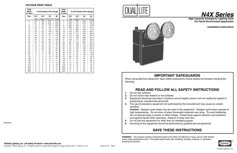
6. Connect remote lamps (if used) to blue (+, fused) and yellow (–) leads (10) (Fig.2orFig.3).
7. Connect120or277VACinputconnectionstotransformer(Fig.2orFig.3). Connect green wire to
building ground.
Note: insulate the unused transformer lead to prevent potential shock hazard.
Dependingonthetypeofunitbattery,followsteps8through16below.
•UnitsSuppliedWithLead-CalciumBatteries
8. Placebattery(8) into housing (2).
9. Determine proper battery orientation from Fig.2(singleharnessleadconnection).Batteryispositionedtotheleftofthecircuit
board.
10.Connectpositive(+,red)andnegative(–,yellow) battery harness leads from printed circuit board to corresponding battery
terminals as shown in Fig.2.
11. Check all wiring for loose or missing connections.
12.Replacecover.Tightencoverscrews.
13.Aimlamp heads (5) to properly illuminate the path of egress.
14.EnergizeunitwithACpower.
Note: Allow unit to charge for 24 hours prior to performing initial test.
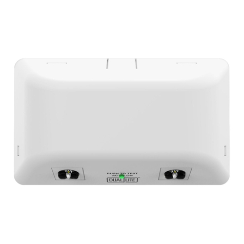
15.Pressandholdthe“TEST”button(seeFig.2 for “TEST”buttonlocation)toconrmilluminationandproperaimingof
emergency lamps. (“AC ON” indicator LED should go off). Release the “TEST”button;emergencylampsshouldextinguish.
Normal operation begins.
16. Normal Operation: with power supplied, “AC ON” LED indicator is illuminated and emergency lamps are off.
•UnitsSuppliedWithNickelCadmiumBatteries
8. Placebattery(8) into housing (2).
9. Determine proper battery orientation from Fig.3(singleordoubleharnessleadconnections).Batteryispositionedtotheleftof
the circuit board.
10. Connect battery harness leads from printed circuit board to corresponding battery harness leads as shown in Fig.3.
11. Check all wiring for loose or missing connections.
12.Replacecover.Tightencoverscrews.
13.Aimlamp heads (5) to properly illuminate the path of egress.
14.EnergizeunitwithACpower.
Note: Allow unit to charge for 24 hours prior to performing initial test.
15.Pressandholdthe“TEST”button(seeFig.3 for “TEST”buttonlocation)toconrmilluminationandproperaimingof
emergency lamps. (“AC ON” indicator LED should go off). Release the “TEST”button;emergencylampsshouldextinguish.
Normal operation begins.
16. Normal Operation: with power supplied, “AC ON” LED indicator is illuminated and emergency lamps are off.
ROUTINE TEST CYCLING
1. Everythree(3)months:Iftherehasbeennopowerfailure,pressandholdthe“TEST”buttonforatleastthirty(30)secondsto
conrmemergencylampoperation.Release“TEST” button to return to battery charging mode.
2. Onceayear:Performafullbatteryconditioningcyclebyde-energizingtheACcircuittowhichtheunitisconnected,andallow
theunittooperateforninety(90)minutesonbatterypower.Followingsuccessfultest,energizeACcircuittobeginbattery
charging cycle.
REPLACING EMERGENCY LAMPS AND BATTERIES
General
a.De-energizetheACpowersupplytotheunit.
b.Removeenclosurecover.
c.Disconnectpositive(+,red)batterylead
(nickel cadmium models-disconnectbatteryandprintedcircuitboardconnectors).
•ReplacingUnitEmergencyLamp •ReplacingUnitBattery
1.Removediffuserlensfrom 1. Removedefectivebattery.Recycleresponsibly.
lamphousingbypryinglens ReplacewithgenuinePrescolitebattery.
adjacent to tab slot (see Fig.4) 2. Placenewbatteryinenclosure.Make
2.Removeandreplacelamp. connectionsfollowingstepsoutlinedabove.
(refer to unit product label 3. Test unit.
forspeciclamptype)
Fig.1
Fig.3 Single and Double Harness Lead
Connections
Nickel-CadmiumBatteryModels
Fig.2 Single Harness Lead Connection
Lead-CalciumBatteryModels
Fig.4
