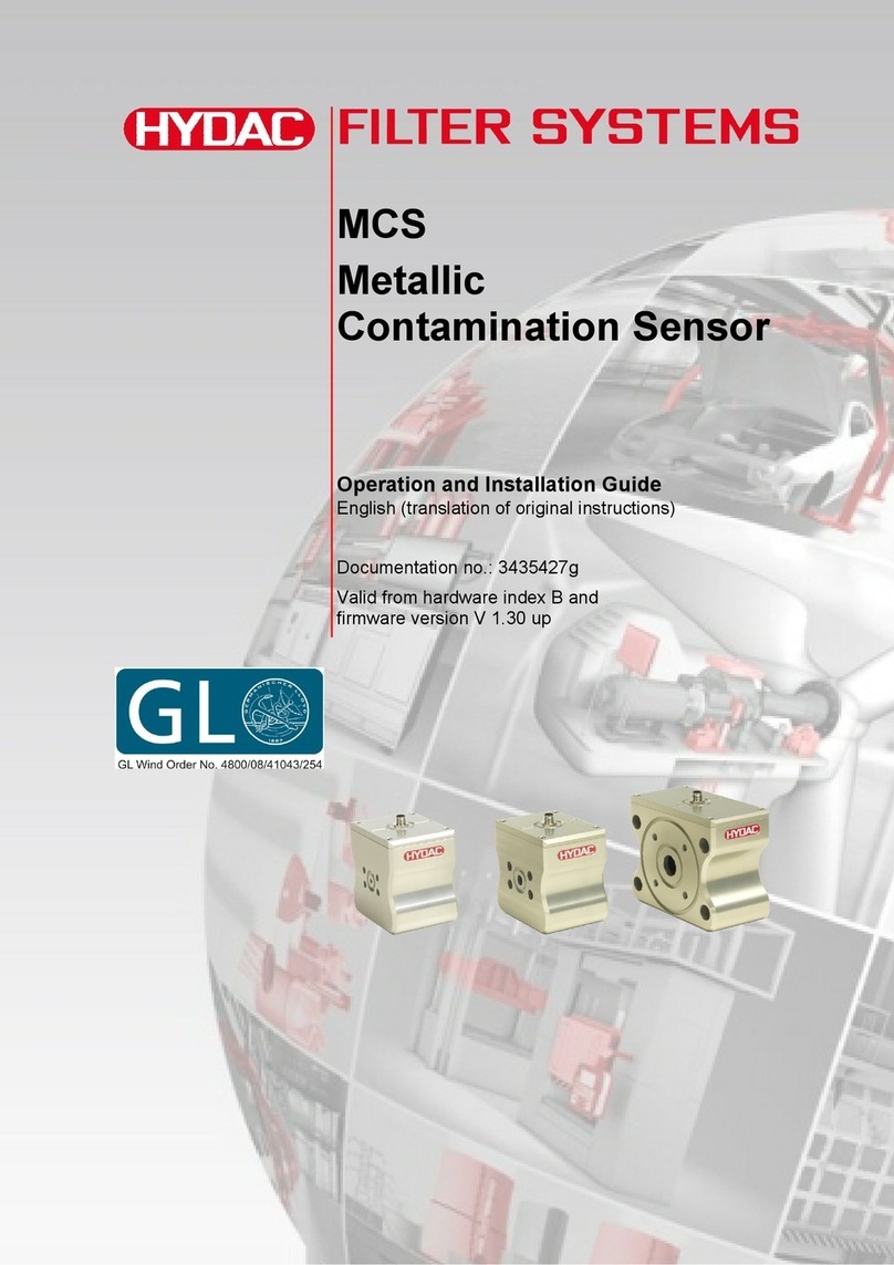
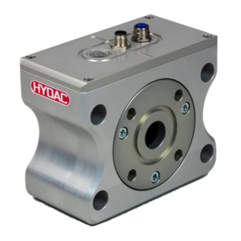
Hydac MCS 13 series Quick start guide

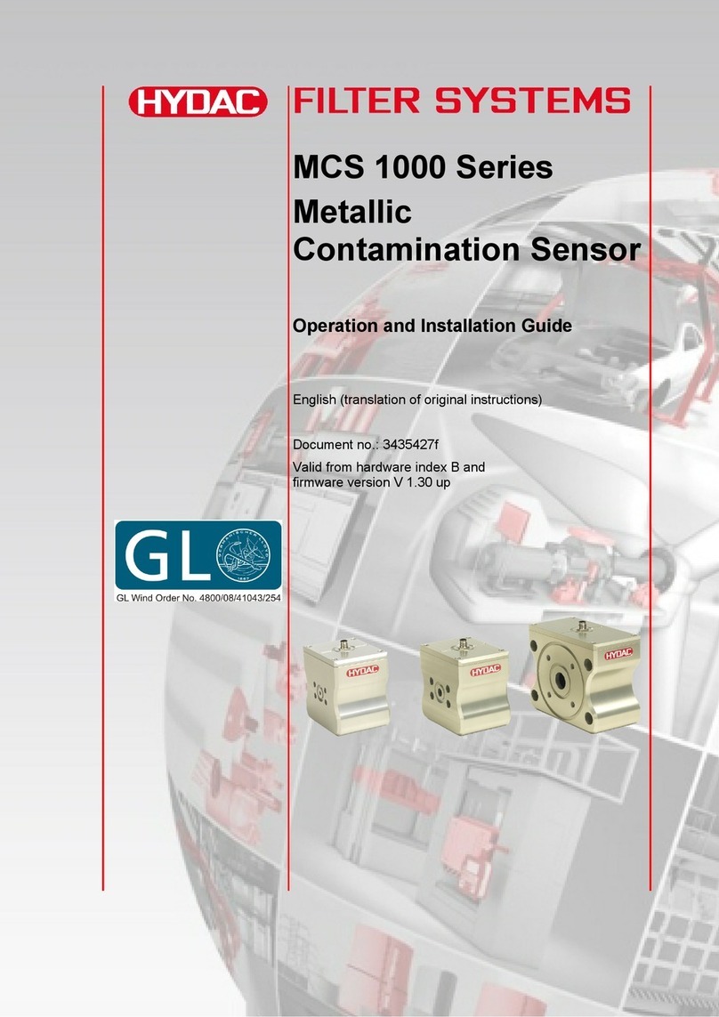
MCS
Metallic
Contamination Sensor
Operation and Installation Guide
English (translation of original instructions)
Documentation no.: 3950943b
Valid from hardware index B and
firmware version V 1.4x up

Content
MCS
en
Page 2 / 80
BeWa MCS1000 3950943b V14x en-us 2018-12-04.docx
2018-12-04
Content
Content ..........................................................................................................2
General ..........................................................................................................6
Imprint..........................................................................................................6
Documentation Representative ...................................................................6
Purpose of this manual................................................................................6
Target group of the manual .........................................................................7
Target group - Required qualifications/training............................................8
Illustrations in the manual............................................................................9
Illustration of the layout ............................................................................9
Representation of procedural instructions..............................................10
Representation of warning/general safety information ...........................10
Signal words and their meaning in the general safety information .........11
Representation/explanation of pictograms.................................................11
Supplementary symbols ............................................................................12
Exclusion of liability/warranty.....................................................................13
Notes on copyright.....................................................................................13
Validity of this manual................................................................................13
General Safety Information........................................................................14
Product overview........................................................................................15
Scope of delivery.......................................................................................15
Scope of delivery for MCS 13xx.............................................................15
Scope of delivery for MCS 14xx.............................................................16
Scope of delivery for MCS 15xx.............................................................17
Dimensions................................................................................................18
Dimensions MCS 13xx...........................................................................18
Dimensions of the MCS 13xx with the Ethernet module.........................19
Dimensions MCS 13xx with flange adapter set (optional
accessories)...........................................................................................20
Dimensions MCS 14xx...........................................................................21
Dimensions for MCS 14xx with Ethernet................................................22
Dimensions MCS 14xx with flange adapter set (optional
accessories)...........................................................................................23
Dimensions MCS 15xx...........................................................................24
Dimensions for MCS 15xx with Ethernet................................................25
Dimensions MCS 15xx with flange adapter set (optional
accessories)...........................................................................................26
Proper/Designated Use .............................................................................27
Improper use or use deviating from intended use......................................27
Technical Data...........................................................................................28
Decoding the type label.............................................................................30

Content
MCS
en
Page 3 / 80
BeWa MCS1000 3950943b V14x en-us 2018-12-04.docx
2018-12-04
Model Code............................................................................................31
Storage and transport ................................................................................32
Assembly, installation and commissioning .............................................33
Mechanical installation/assembly ..............................................................33
Connecting MCS13xx / 14xx via flange adapter set...............................34
Fastening sensor to underside ..................................................................35
Fastening MCS 13xx / MCS 14xx...........................................................36
Fastening MCS 15xx..............................................................................36
Fastening MCS 15xx using angle fastening set .....................................37
Connecting MCS 15xx using pipe adapter set .......................................37
Connecting MCS 15xx using flange adapter plate (accessory)..............38
MCS 15xx via SAE 4" per ISO 6162-1 (4xM16).....................................39
Hydraulic installation / assembly................................................................40
Diagram - flow rate, differential pressure
p
and viscosity
................40
Electrical installation / assembly................................................................42
Plug pin assignment...............................................................................42
Connection cable - Assignment / Color coding.......................................43
Connecting cable wires..........................................................................44
Examples of connection.........................................................................44
Connection: operation voltage = measurement voltage......................45
Using switching output 1..................................................................46
Using switching output 2..................................................................46
Using switching output 1 and 2........................................................46
Connection: operation voltage ≠ measurement voltage ......................47
Using switching output 1..................................................................47
Using switching output 2..................................................................47
Using switching output 1 and 2........................................................48
Using the switching outputs.......................................................................48
Switching output - FE.NFE (factory setting) ...........................................49
Switching output - ALL.RDY...................................................................49
Switching output - ALARM .....................................................................49
Switching logic "active low" ....................................................................49
Example: Operation - 1 particle detected............................................50
Example: Operation - no particle detected..........................................50
Example: Operation - several particles detected.................................51
Switching logic "active high"...................................................................51
Example: Operation - 1 particle detected............................................51
Example: Operation - no particle detected..........................................52
Example: Operation - several particles detected.................................52
Switching output "Device Ready"...........................................................53
Parameterizing sensor/reading measured values......................................54

Content
MCS
en
Page 4 / 80
BeWa MCS1000 3950943b V14x en-us 2018-12-04.docx
2018-12-04
Connecting MCS 1000 to SMU 1200 .....................................................54
Connecting MCS to CSI-D-5 (Condition Sensor Interface).....................55
Connecting MCS to HMG 3000..............................................................56
Factory settings ..........................................................................................57
Channel default settings............................................................................57
Detection limits..........................................................................................57
Default Ethernet settings ...........................................................................57
Operation.....................................................................................................58
Evaluating measurement results ...............................................................58
Menu structure...........................................................................................59
Overview - Power Up Menu ...................................................................59
Overview - Measuring Menu...................................................................60
PowerUp Menu..........................................................................................61
MODE - select operating mode..............................................................61
S.TIME - Set storing interval ..................................................................61
SEL.COM - Set protocol.........................................................................61
ADRESS –Set bus address...................................................................61
DFAULT - Reset to factory setting..........................................................61
CANCEL - cancel without saving............................................................61
SAVE - save changes ............................................................................61
Measuring menu........................................................................................62
DSPLAY - Show measured variable.......................................................62
SWT.OUT –Set the switching output.....................................................63
SWT.LOG - Set logic at the switching output .........................................63
SWT.PLS - Set pulse length at the switching output..............................64
SWT.TST –Set test pulse at the switching output .................................64
ALARM –Setting limit values.................................................................64
CANCEL - cancel without saving............................................................65
SAVE - Save changes............................................................................65
Maintenance................................................................................................66
Calibrating the sensor................................................................................66
Customer Service / Service.......................................................................66
Troubleshooting/fault rectification............................................................67
Error analysis / remedy..............................................................................67
Error status - "active high" and "active low"............................................69
Error status 1 "active low" ...................................................................69
Error status 1 "active high"..................................................................69
Error status 2 "active low" ...................................................................70
Error status 2 "active high"..................................................................71
Error status - "Device Ready".................................................................71
Removing / Disposal...................................................................................72

Content
MCS
en
Page 5 / 80
BeWa MCS1000 3950943b V14x en-us 2018-12-04.docx
2018-12-04
Appendix .....................................................................................................73
Spare Parts and Accessories ....................................................................73
Glossary ......................................................................................................76
Ferromagnetic (Fe)....................................................................................76
Non-ferromagnetic (nFe) ...........................................................................76
Certification................................................................................................76
Basics of GL certification........................................................................77
Germanischer Lloyd Industrial Services GmbH, renewable
energies .................................................................................................77
Index ............................................................................................................78

General
MCS
en
Page 6 / 80
BeWa MCS1000 3950943b V14x en-us 2018-12-04.docx
2018-12-04
General
In this chapter, you will find helpful notes on handling these instructions.
Imprint
Publisher and responsible for the content:
HYDAC FILTER SYSTEMS GMBH
Postfach 1251
66273 Sulzbach / Saarland
Germany
Phone:
+49 6897 509 01
Fax:
+49 6897 509 9046
E-mail:
Homepage:
www.hydac.com
Court of registration:
Saarbrücken, HRB 17216
Executive directors:
Mathias Dieter,
Dipl.Kfm. Wolfgang Haering
Documentation Representative
Mr. Günter Harge
c/o HYDAC International GmbH, Industriegebiet, 66280 Sulzbach / Saar
Phone:
+49 6897 509 1511
Fax:
+49 6897 509 1394
E-mail:
Purpose of this manual
Please read this manual before you use this product for the first time or if you
have been asked to carry out other work on the product
The use and the handling of the product described in the following, as well as
its use, are not self-explanatory and are described in detail in this manual
and the associated technical documentation.
This manual will help you to use the product as intended, properly,
effectively, and safely. Therefore, you are requested to read the following

General
MCS
en
Page 7 / 80
BeWa MCS1000 3950943b V14x en-us 2018-12-04.docx
2018-12-04
chapters attentively and carefully. Please refer to it every time you require
decisive details.
This manual informs and warns you of risks, against which the risk reduction
through the design and protective measures may not be effective or not fully
effective.
Target group of the manual
This manual was created for the following target group.
Target group
Tasks
Owner
This manual and the associated documents must be kept
accessible at the installation location of the product and
also for later use.
Ask the employees to read and follow the manual and the
documents delivered along with it, in particular, the safety
and warning instructions.
Observe the additional product-related instructions and
requirements.
Specialist
personnel
Read, observe and follow this manual and the associated
documents, in particular, the safety and warning
instructions.

General
MCS
en
Page 8 / 80
BeWa MCS1000 3950943b V14x en-us 2018-12-04.docx
2018-12-04
Target group - Required qualifications/training
Persons who work on the product must be aware of the hazards associated
with its use.
Auxiliary and specialist personnel must have read and understood the
operating instructions, in particular the General Safety Information and
instructions, and applicable regulations before beginning work.
The operating instructions and applicable regulations are to kept so they are
accessible for operating and specialist personnel.
These operating instructions are intended for:
Auxiliary personnel: such persons have been instructed about the product
and informed about potential hazards that can result from improper use.
Specialist personnel: such persons with corresponding specialist training and
several years' work experience. They are able to assess and perform the
work assigned to them, they are also able to recognize potential dangers.
Activity
Person
Knowledge
Transport / storage
Forwarding
agent
Auxiliary
personnel
No specialist knowledge
required
Hydraulic / electrical
installation,
First commissioning
Maintenance
Troubleshooting
Repair,
Decommissioning
Disassembly
Specialist
personnel
Safe handling/use of tools
Fitting and connection of
hydraulic lines and
connections
Fitting and connection of
electrical lines, electrical
machinery, sockets, etc.
Product-specific knowledge
Operation
Operations control
Specialist
personnel
Product-specific knowledge
Knowledge about how to
handle operating media.
Disposal
Specialist
personnel
Knowledge about reuse

General
MCS
en
Page 9 / 80
BeWa MCS1000 3950943b V14x en-us 2018-12-04.docx
2018-12-04
Illustrations in the manual
You will find illustrations in this manual. You can find details regarding these
in the following chapters.
Illustration of the layout
de
HYDACFiltertechnikGmbH
BeWa123456ade
Seite x
Produkt/Kapitel
200x-xx-xx
The documentation number with its index enables you to order another copy
of the operating and maintenance instructions. The index is incremented
every time the manual is revised or changed.
Note that the method described for locating specific information
does not release you from your responsibility of carefully reading
these instructions prior to starting the unit up for the first time and
at regular intervals in the future.
The manual contains a table of contents, an index and a glossary.
Chapter description
Page number
Edition date
Document language
Documentation no.
with index/
file name

General
MCS
en
Page 10 / 80
BeWa MCS1000 3950943b V14x en-us 2018-12-04.docx
2018-12-04
Representation of procedural instructions
There are these two following representations in the case of procedural
instructions:
Procedural instructions with a fixed sequence
Procedural instructions, whose sequence must be complied with without fail
are listed with sequential numbering (1., 2., 3., etc.).
An example for procedural instructions with a fixed sequence:
1. Remove the transport securing device.
2. First fill the product.
3. Switch the product on.
Procedural instructions with a random sequence
Procedural instructions that have a random sequence are listed as bullet
points (-).
An example of a procedural instruction with a random sequence:
- Clean the display
- Rinse the product
Representation of warning/general safety information
All the warning / general safety information in this manual are highlighted with
pictograms and signal words. The pictogram and the signal word indicate the
severity of the danger.
Warning/general safety information is listed before an activity and is laid out
as follows.
HAZARD SYMBOL
SIGNAL WORD
Type and source of danger
Consequence of the danger
►Measures to avert the danger

General
MCS
en
Page 11 / 80
BeWa MCS1000 3950943b V14x en-us 2018-12-04.docx
2018-12-04
Signal words and their meaning in the general safety information
In these instructions you will find the following signal words:
DANGER
DANGER –The signal word indicates a hazardous situation with a high level
of risk, which, if not avoided, will result lethal or serious injury.
WARNING
WARNING –The signal word indicates a hazardous situation with a medium
level of risk, which, if not avoided, can result lethal or serious injury.
CAUTION
CAUTION –The signal word indicates a hazardous situation with a low level
of risk, which, if not avoided, can result in minor or moderate injury.
NOTICE
NOTICE –The signal word indicates a hazardous situation with a high level
of risk, which, if not avoided, will result in damage to property.
Representation/explanation of pictograms
The following are the safety symbols / pictograms in this manual. They
indicate specific dangers to persons, property or to the environment. Observe
these safety symbols / pictograms and act with particular caution in such
cases. Always keep all symbols / pictograms intact and legible.
Warning signs used
These signs are listed for all general safety information and instructions in
these operating instructions which indicate particular dangers to persons,
property or the environment.
General hazard

General
MCS
en
Page 12 / 80
BeWa MCS1000 3950943b V14x en-us 2018-12-04.docx
2018-12-04
Signs used for giving orders
These symbols are listed for all general safety information and instructions in
these operating instructions that refer to particular dangers to persons,
property or the environment.
Signs used for the required specialist personnel
These symbols show the required training/knowledge for installation work
and/or maintenance work.
Specialist personnel - Electrical
Such persons have specific specialist training and several
years' work experience. They are able to assess and
perform the work assigned to them, they are also able to
recognize potential dangers.
Specialist personnel - Mechanical
Such persons have specific specialist training and several
years' work experience. They are able to assess and
perform the work assigned to them, they are also able to
recognize potential dangers.
Supplementary symbols
You will find the following symbols in the manual as additional details:
Tip for handling the product
Required tools

General
MCS
en
Page 13 / 80
BeWa MCS1000 3950943b V14x en-us 2018-12-04.docx
2018-12-04
Exclusion of liability/warranty
For the warranty provided by us, please refer to our terms of delivery. They
are made available to you at the conclusion of the contract at the latest. In
addition, you will find these under www.hydac.com -> General terms and
conditions.
This manual was prepared to the best of our knowledge. Nevertheless and
despite the greatest care, it cannot be excluded that mistakes could have
crept in. Therefore please understand that, in the absence of any provisions
to the contrary hereinafter, our warranty and liability –for any legal reasons
whatsoever –are excluded in respect of the information in these instructions.
In particular, we shall not be liable for lost profit or other financial loss.
This exclusion of liability does not apply in cases of intent and gross
negligence. Moreover, it does not apply to defects which have been
deceitfully concealed or whose absence has been guaranteed, nor in cases
of culpable harm to life, physical injury and damage to health. If we
negligently breach any material contractual obligation, our liability shall be
limited to foreseeable damage. Claims due to the Product Liability shall
remain unaffected.
Notes on copyright
All copyrights for this manual lies with the manufacturer. Any part of this
manual may cannot be reproduced, used or copied in any form with the help
of electronical systems without the written consent of the manufacturer. Any
infringements of the above shall be liable to damage compensation.
Validity of this manual
The diagrams and visualizations in this manual are meant for general
illustration purposes. Therefore, representations and functional options can
deviate from those of the delivered product.
We reserve the right to changes to the contents of this manual without prior
notice.

General Safety Information
MCS
en
Page 14 / 80
BeWa MCS1000 3950943b V14x en-us 2018-12-04.docx
2018-12-04
General Safety Information
The product has been built according to the provisions, directives and
standards valid at the time of delivery and satisfies the current safety
requirements. Any residual hazards are indicated by the general safety
information and are described in this manual.
Observe all the safety and warning instructions attached to the product and
always keep them up to date and easily legible.

Product overview
MCS
en
Page 15 / 80
BeWa MCS1000 3950943b V14x en-us 2018-12-04.docx
2018-12-04
Product overview
Scope of delivery
Scope of delivery for MCS 13xx
The MetallicContamination Sensor MCS 13xx comes packed and factory-
assembled. Before commissioning the sensor, please check no items are
missing from the package.
The following items are supplied:
Qty.
Description
1
MetallicContamination Sensor, MCS 13xx
1
O-ring (18.7 x 3.53 NBR 70 Shore)
1
Operation and Installation Guide (this document)

Product overview
MCS
en
Page 16 / 80
BeWa MCS1000 3950943b V14x en-us 2018-12-04.docx
2018-12-04
Scope of delivery for MCS 14xx
The MetallicContamination Sensor MCS 14xx comes packed and factory-
assembled. Before commissioning the sensor, please check no items are
missing from the package.
The following items are supplied:
Qty.
Description
1
MetallicContamination Sensor, MCS 14xx
1
O-ring (25 x 3.53 NBR 70 Shore)
1
Operation and Installation Guide (this document)

Product overview
MCS
en
Page 17 / 80
BeWa MCS1000 3950943b V14x en-us 2018-12-04.docx
2018-12-04
Scope of delivery for MCS 15xx
The MetallicContamination Sensor MCS 15xx comes packed and factory-
assembled. Before commissioning the sensor, please check no items are
missing from the package.
The following items are supplied:
Qty.
Description
1
MetallicContamination Sensor, MCS 15xx
1
o-ring (47.22 x 3.53 NBR 70 Shore)
1
O-ring (110.72 x 3.53 NBR 70 Shore)
1
Operation and Installation Guide (this document)

Product overview
MCS
en
Page 18 / 80
BeWa MCS1000 3950943b V14x en-us 2018-12-04.docx
2018-12-04
Dimensions
The dimensions for the available sizes vary. The dimensions for each size
can be found below.
Dimensions MCS 13xx
Flange image SAE 3/4"
All dimensions in mm.

Product overview
MCS
en
Page 19 / 80
BeWa MCS1000 3950943b V14x en-us 2018-12-04.docx
2018-12-04
Dimensions of the MCS 13xx with the Ethernet module
Flange image SAE 3/4"
All dimensions in mm.

Product overview
MCS
en
Page 20 / 80
BeWa MCS1000 3950943b V14x en-us 2018-12-04.docx
2018-12-04
Dimensions MCS 13xx with flange adapter set (optional accessories)
All dimensions in mm.
Other manuals for MCS 13 series
1
This manual suits for next models
2
Table of contents
Other Hydac Accessories manuals

Hydac
Hydac ContaminationSensor CS1220 VIMS Manual

Hydac
Hydac CS 1x11-A-0-0-0-0/-000 Instruction manual

Hydac
Hydac VibrationSensor VS 3000 Quick start guide

Hydac
Hydac HAT 1425 User manual

Hydac
Hydac MCS 13 series Quick start guide

Hydac
Hydac CS 1000 Series Manual

Hydac
Hydac CS 2000 series Operating instructions

Hydac
Hydac MCS****-C062 series Quick start guide

Hydac
Hydac CS 1000 Series Troubleshooting guide

Hydac
Hydac MCS1 T001 Series Quick start guide