manuals.online logo
Brands
  1. Home
  2. •
  3. Brands
  4. •
  5. Hytronik
  6. •
  7. Accessories
  8. •
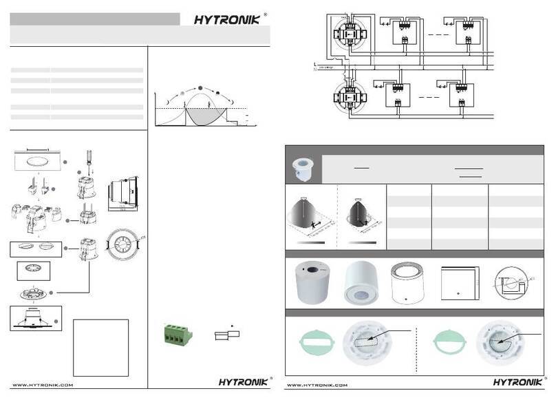
  9. Hytronik HIR23 Quick guide

Hytronik HIR23 Quick guide

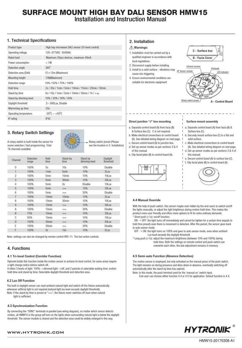
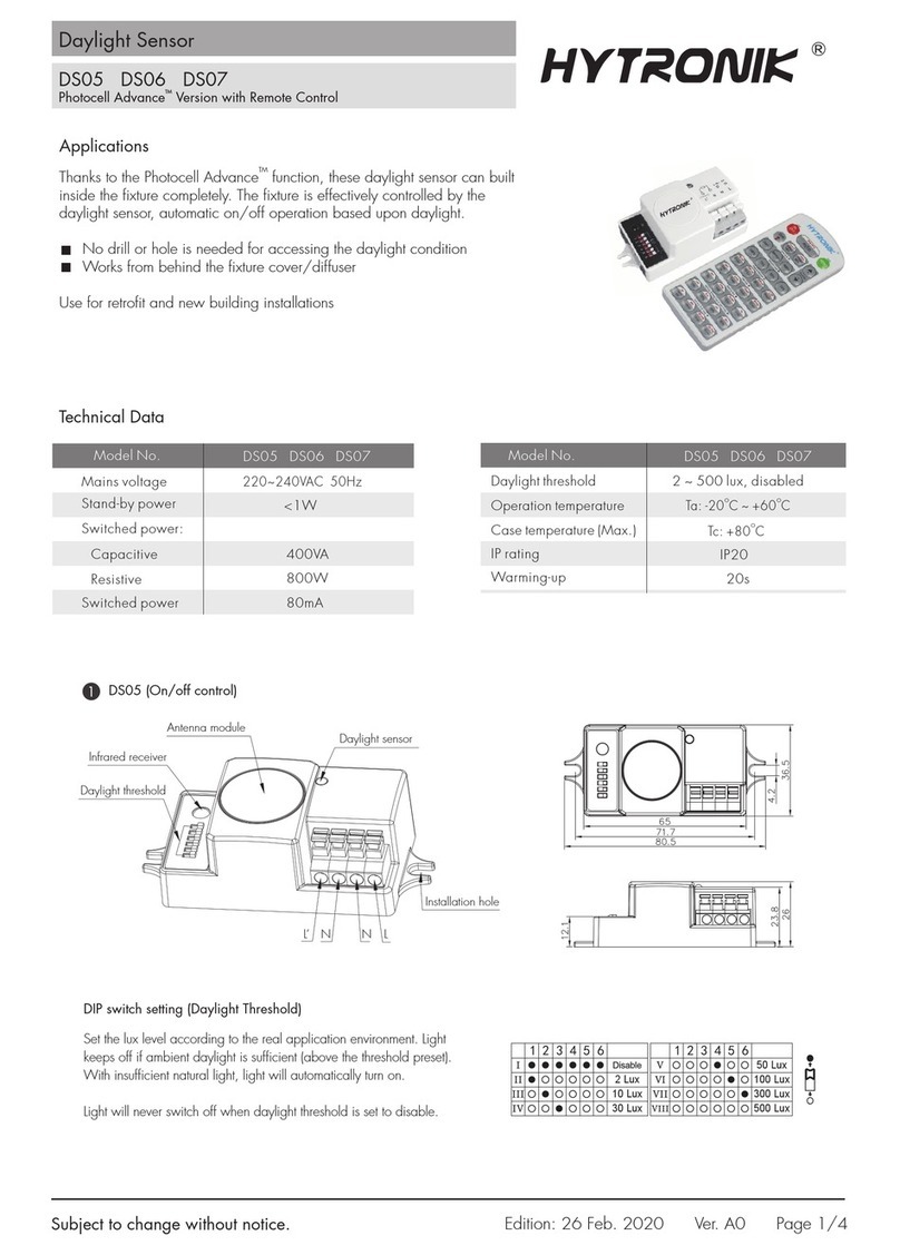
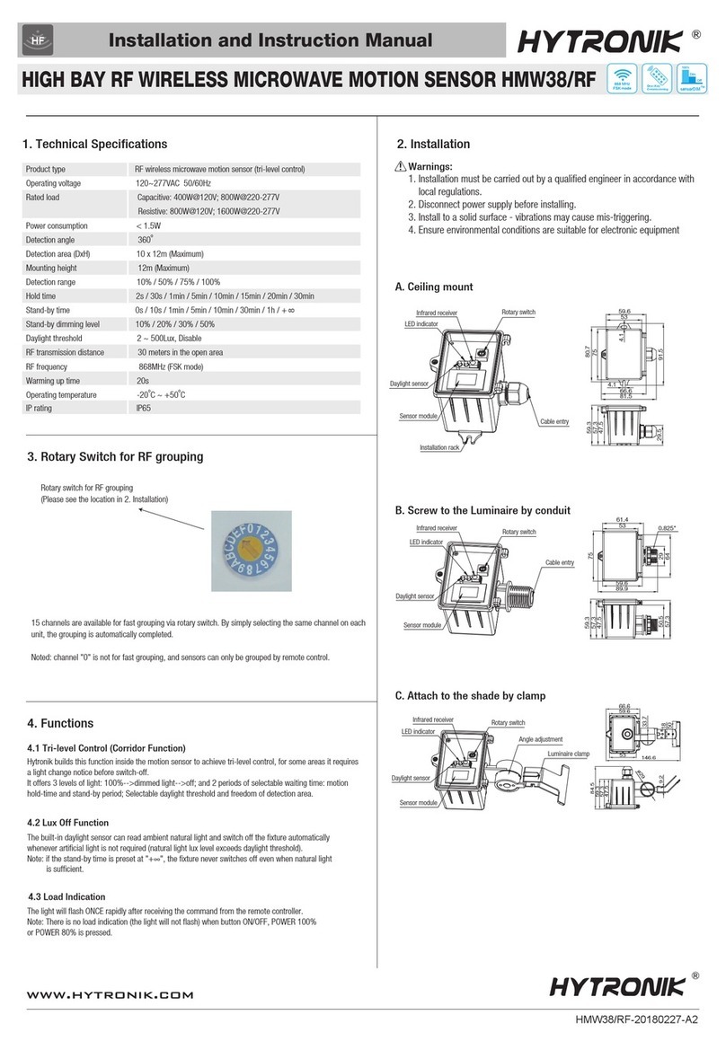
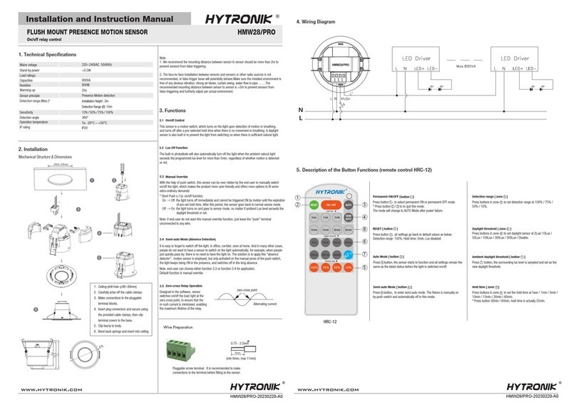
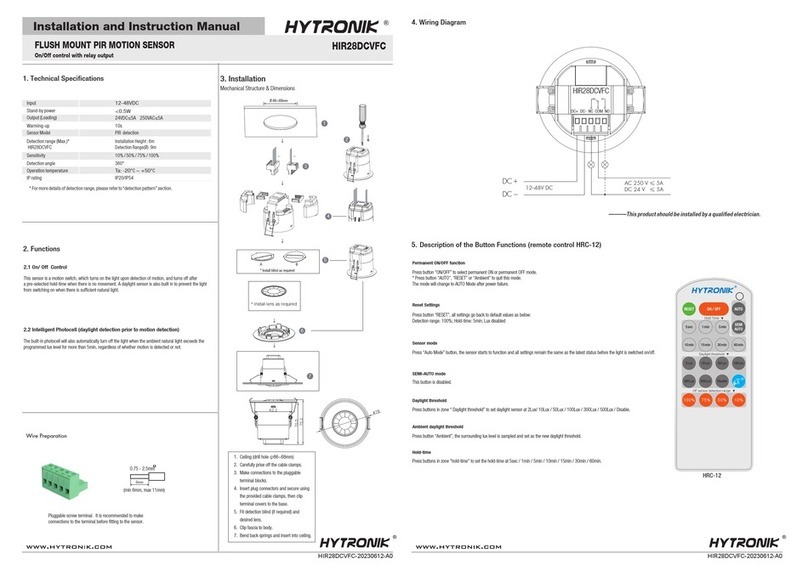
1. Technical Specifications
Product type Tri-level control PIR DALI sensor
Operating voltage 9.5 ~ 22.5VDC ( suitable DALI power supply)
Input current < 8mA
Power consumption < 0.5W
Detection angle 360o
Detection area (DxH) 10 x 3m (Tangential)
Mounting height 5m (Maximum)
Detection range 10% / 50% / 75% / 100%
Hold time 2s / 30s / 1min / 5min / 10min / 15min / 20min / 30min
Stand-by time 0s / 10s / 1min / 5min / 10min / 30min / 1h / +∞
Stand-by dimming level 10% / 20% / 30% / 50%
Daylight threshold 2Lux / 10Lux / 50Lux / Disable
Warmming-up time 30s
Operating temperature -20oC ~ +50oC
3. Rotary Switch Settings
A rotary switch is built inside the sensor for
scene selection / fast programming. Total
16 channels available:
Note: settings can also be changed by remote control HRC-11. The last action controls.
FLUSH MOUNT PIR DALI SENSOR HIR23
Installation and Instruction Manual
Rotary switch preset (Please
see the location in 2. Installation)
DALI group selection (Please
see the location in 2. Installation)
Detection
range
Channel
0
1
2
3
4
5
6
7
8
9
A
B
C
D
E
F
100%
100%
100%
100%
100%
100%
100%
100%
100%
100%
100%
75%
50%
100%
100%
100%
5s
1min
5min
5min
5min
5min
5min
10min
10min
10min
10min
10min
10min
30min
30min
5s
10s
5min
10min
30min
0s
+∞
+∞
10min
30min
+∞
+∞
+∞
+∞
+∞
+∞
10s
10%
10%
10%
10%
Disable
10%
30%
10%
10%
10%
30%
10%
10%
10%
30%
10%
Disable
2Lux
10Lux
30Lux
10Lux
30Lux
Disable
2Lux
10Lux
30Lux
Disable
30Lux
10Lux
50Lux
Disable
2Lux
Hold
time
Stand-by
time
Stand-by
dimming level
Daylight
threshold
5. Functions
Hytronik builds this function inside the motion sensor to achieve tri-level control, for some areas require a
light change notice before switch-off.
It offers 3 levels of light: 100%-->dimmed light-->off; and 2 periods of selectable waiting time: motion
hold-time and stand-by period; Selectable daylight threshold and freedom of detection area.
This DALI sensor is designed for incoporated in the DALI system, taking command from the DALI master,
accepting and carrying out the grouping work with up to 64 lumanaires. It can switch on/off, or dim the
assigned group members and feed back the status to the DALI master.
By connecting the DALI terminals in parallel (see wiring diagram), no matter which sensor detects motion,
all HMW23 in the group will turn on the lights when surrounding natural light is below the daylight
threshold. The sensor antenna is shared and the detection area could be widely enlarged in this way.
5.1 Tri-level Control (Corridor Function)
5.2 Synchronization Function
4. DALI group selection
DALI group configuration can be done on PC or on the rotary switch:
1. There are 16 channels available on the rotary switch. “0” is
for DALI broadcast, the rest 15 channels is for end user to
define the application unit.
2. PC grouping can overwrite rotary switch grouping, the last
setting controls.
3. The rotary switch channel is corresponding to the groups
listed below:
Switch channel DALI group Switch channel DALI group
0
1
2
3
4
5
6
7
broadcast
group 0
group 1
group 2
group 3
group 4
group 5
group 6
8
9
A
B
C
D
E
F
group 7
group 8
group 9
group 10
group 11
group 12
group 13
group 14
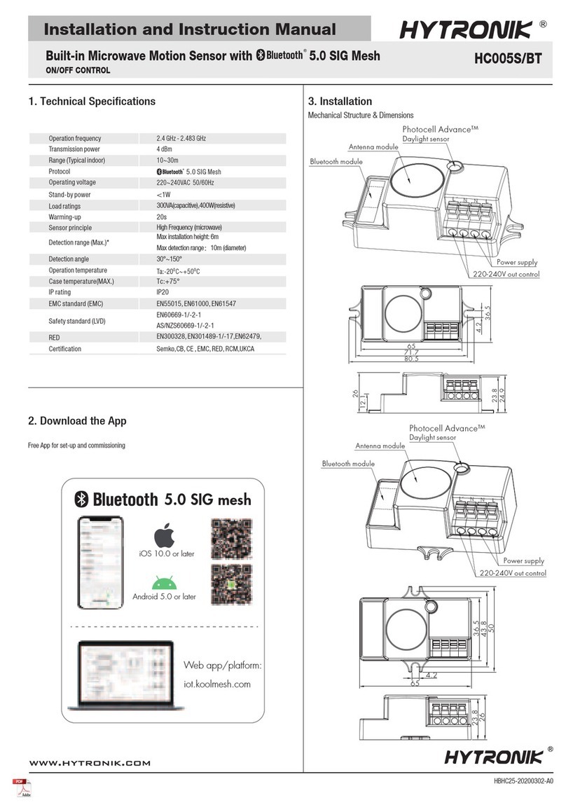
2. Installation
Warnings:
1. Installation of the sensor involves connecting it to the mains supply. This work must be
carried out by a specialist in accordance with electrotechnical regulations.
2. Disconnect supply before installing.
3
4
2
(1) Sensor inset
(2) Lens pluggable
(3) Protection cover (covers the
high-voltage terminals, and leaves
the DALI terminals exposed).
(4) Ceiling (drill hole O 70mm).
64.7
o85
68.1
73.3
56
70mm
HIR23-20181226-A1
Infrared receiver
Photocell
LED indicator
Rotary switch preset
DALI group selection
1
PIR
Blind
A
B
Blind
Note: the blinds are optional, they may be inserted
behind the lens for focussing the detection
range.
Description of the
Button Functions
(remote control HRC-11)
8.
Detection range [ zone ]
Press buttons in zone to set detection range at 100% / 75% /
50% / 10%.
Stand-by time [ zone ]
Press buttons in zone to set the stand-by period at 0s / 10s /
1min / 5min / 10min / 30min / 1h / +∞.
Note: “0s” means on/off control; “+∞” means bi-level control, 100%
on when motion detected, and remains at the stand-by dimming
level when no presence after hold-time.
Daylight threshold [ zone ]
Press button Shift, the red LED is on for indication.
2. Press button , the ambient lux level is sampled and set as the
new daylight threshold.
Hold time [ zone ]
Press buttons in zone to set the hold time at 2s / 30s / 1min /
5min / 10min / 15min / 20min / 30min.
Note: 1.To set hold-time at 30s / 5min / 15min / 30min, press
button Shift at first.
2. 2s is for test purpose only, stand-by period and daylight
sensor settings are disabled in this mode.
*To exit from Test mode, press button or any button in zone .
8
3
3
9
Press buttons in zone to set the daylight sensor at 2Lux / 10Lux /
50Lux/X[/X[/X[ or Disable.
Ambient daylight threshold [ button
10
]
1.
11
12
12
11
11
10
9
8
Permanent ON/OFF [ ]
Press button , to select permanent ON or permanent OFF mode.
* Press button / to resume automatic operation.
The mode will change to AUTO Mode after power failure.
Power output [ button ]
All buttons in zone are disabled.
button
Auto Mode [ button ]
Brightness +/- [ button ]
All buttons in zone are disabled.
Scene prog. [ zone ] (One-key-commissioning)
Shift [ button ]
RESET[ button ]
Press button , all settings go back to the rotary switch settings.
Press button to initiate automatic mode.The sensor starts working
and all settings remain as before the light was switched ON/OFF.
Note: the function of Semi-auto is disabled.
1. Press button “Start” to program.
2. Select the buttons in “Detection range”, / “Daylight threshold”,
“Hold time”, “Stand-by time”, “Stand-by dimming level” to
set all parameters.
3. Press button “Memory” to save all the settings programmed in the
remote control.
4. Press button “Apply” to set the settings to each sensor unit(s).
For example, to pre-set detection range 100%, daylight threshold
Disable, hold time 5min, stand-by time +∞, stand-by dimming level
30%, steps should be:
Press button Start, button 100%, Disable, Shift, 5min,
Shift, +∞, 30%, Memory. By pointing to the sensor unit(s)
and pressing Apply, all settings are passed on the sensor(s).
Press button , the LED on the top left corner is on for indication.
All values / settings in RED are in valid for 20 seconds.
1
2
2
3
3
4
4
5
6
7
7
7
7
3
3
8
8 9
10
10 11
1312
11 12 13
6
5
1
24
2
6. Wiring Diagram
HIR23-20181226-A1
L
N
DALI power
supply DALI driver
Bus-mastering
DALI master
DALI driver DA1 DA2 DA1 DA2
HIR23HIR23
Hytronik Industrial Ltd. | www.hytronik.com
3rd Floor, block C, complex building, 155#, Bai'gang road south,
Bai'gang village, Xiao Jin Kou town, Huicheng district, Huizhou 516023
Tel: 86-752-2772020 Fax: 86-752-2777877
HRC-11
&
A

III
6
8
10
11
2
4
1
3
7
9
5
12
13
14
Stand-by dimming level [ zone ]
Press buttons in zone to set the stand-by dimming level at 10% /
20% / 30% / 50%.
Note: the function of 24h/12h/4h/30s are disabled.
13
Dual tech & RF mode [ zone ]
All buttons in zone are disabled.
14
14
13
Detection Pattern7.
Tangential movement 10m
Radial movement 8m
3m 3m
Tangential movement 5m
Radial movement 4m
1
50% blind A
Tangential movement 10m
4m
4m
m
4
3m
7
corridor blind B

Other Hytronik Accessories manuals

Hytronik HEC9025/I Quick guide

Hytronik

Hytronik HEC9025/I Quick guide

Hytronik HMW32 User manual

Hytronik

Hytronik HMW32 User manual

Hytronik HMW25 Quick guide

Hytronik

Hytronik HMW25 Quick guide

Hytronik HMW30 User manual

Hytronik

Hytronik HMW30 User manual

Hytronik HCD418/DH User manual

Hytronik

Hytronik HCD418/DH User manual

Hytronik HC428V/RF User manual

Hytronik

Hytronik HC428V/RF User manual

Hytronik HIM34 User manual

Hytronik

Hytronik HIM34 User manual

Hytronik HC005S/BT Quick guide

Hytronik

Hytronik HC005S/BT Quick guide

Hytronik HIR27 Quick guide

Hytronik

Hytronik HIR27 Quick guide

Hytronik HMW14 Quick guide

Hytronik

Hytronik HMW14 Quick guide

Hytronik DUAL sense HIM11 Quick guide

Hytronik

Hytronik DUAL sense HIM11 Quick guide

Hytronik HCD038 Quick guide

Hytronik

Hytronik HCD038 Quick guide

Hytronik HC005S/IR Quick guide

Hytronik

Hytronik HC005S/IR Quick guide

Hytronik HMW32 User manual

Hytronik

Hytronik HMW32 User manual

Hytronik HMW34 Quick guide

Hytronik

Hytronik HMW34 Quick guide

Hytronik HCD418/I User manual

Hytronik

Hytronik HCD418/I User manual

Hytronik HEC7430 User manual

Hytronik

Hytronik HEC7430 User manual

Hytronik HBHC25 Quick guide

Hytronik

Hytronik HBHC25 Quick guide

Hytronik HIM30 Quick guide

Hytronik

Hytronik HIM30 Quick guide

Hytronik HC005S/BT Quick guide

Hytronik

Hytronik HC005S/BT Quick guide

Hytronik HIM39/RF Quick guide

Hytronik

Hytronik HIM39/RF Quick guide

Hytronik HIM38/RF Quick guide

Hytronik

Hytronik HIM38/RF Quick guide

Hytronik HIM32 Quick guide

Hytronik

Hytronik HIM32 Quick guide

Hytronik HMW21 Quick guide

Hytronik

Hytronik HMW21 Quick guide

Popular Accessories manuals by other brands

SICK PS30 operating instructions

SICK

SICK PS30 operating instructions

Sentera Controls FCMFX-R Mounting and operating instructions

Sentera Controls

Sentera Controls FCMFX-R Mounting and operating instructions

Azoth Systems O'Dive Complete Instructions Manual

Azoth Systems

Azoth Systems O'Dive Complete Instructions Manual

Pixika LIGHT COLOR 3000 user manual

Pixika

Pixika LIGHT COLOR 3000 user manual

XLAYER X-Pro user guide

XLAYER

XLAYER X-Pro user guide

Allen + Roth EMERALD COVE PS-213-60-EC Assembly instructions

Allen + Roth

Allen + Roth EMERALD COVE PS-213-60-EC Assembly instructions

Hans Grohe Pontos Scout 15887000 Assembly instructions

Hans Grohe

Hans Grohe Pontos Scout 15887000 Assembly instructions

Garmin LIDAR-LITE V4 LED Operation manual and technical data

Garmin

Garmin LIDAR-LITE V4 LED Operation manual and technical data

StarTech.com ST122HD20 quick start guide

StarTech.com

StarTech.com ST122HD20 quick start guide

Infinite L-com SRCN-C413-3 user guide

Infinite

Infinite L-com SRCN-C413-3 user guide

Axor Massaud Toilet Brush with Holder 42235000 Dimensions

Axor

Axor Massaud Toilet Brush with Holder 42235000 Dimensions

BossPac WASP WASP2 user manual

BossPac

BossPac WASP WASP2 user manual

JMTek PBW200 instruction manual

JMTek

JMTek PBW200 instruction manual

Endress+Hauser Nivector FTI26 Brief operating instructions

Endress+Hauser

Endress+Hauser Nivector FTI26 Brief operating instructions

Crestron CH-TEMP-WM Operation guide

Crestron

Crestron CH-TEMP-WM Operation guide

Manitowoc K00117 installation instructions

Manitowoc

Manitowoc K00117 installation instructions

GEIGER SOLIDline Original assembly and operating instructions

GEIGER

GEIGER SOLIDline Original assembly and operating instructions

Leuze electronic ODS 9 Original operating instructions

Leuze electronic

Leuze electronic ODS 9 Original operating instructions

manuals.online logo
manuals.online logoBrands
  • About & Mission
  • Contact us
  • Privacy Policy
  • Terms and Conditions

Copyright 2025 Manuals.Online. All Rights Reserved.