manuals.online logo
Brands
  1. Home
  2. •
  3. Brands
  4. •
  5. Hytronik
  6. •
  7. Accessories
  8. •
  9. Hytronik HIR27 Quick guide

Hytronik HIR27 Quick guide

4. Wiring Diagram
HIR27-20230616-A0
HIR27-20230616-A0
3. Functions
Semi-auto Mode (Absence Detection)3.3
With the help of push-switch, this sensor can be over-ridden by the end-user to manually switch
on/off the light, which makes the product more user-friendly and offers more options to fit some
extra-ordinary demands:
Manual Override
3.2
* Short Push (<1s): on/off function;
On →Off: the light turns off immediately and cannot be triggered ON by motion until the expiration
of pre-set hold-time. After this period, the sensor goes back to normal sensor mode.
Off →On: the light turns on and goes to sensor mode, no matter if ambient Lux level exceeds the
daylight threshold or not.
* Long Push (>1s): adjust the target lux level by turning the light up or down. Both the adjustment on
remote control and push switch can overwrite each other. The last adjustment remains in memory.
Note: if end-user do not want this manual override function, just leave the “push” terminal
unconnected to any wire.
Wire Preparation
0.75 - 2.5mm
8mm
(min 6mm, max 11mm)
1. Technical Specifications
Installation and Instruction Manual
HIR27
FLUSH MOUNT PIR MOTION SENSOR
One DALI Channel Output
Daylight sensor measures the available surrounding natural light, calculates how much electrical light
is needed to reach the total lux expected. The demand is given to the LED driver by DALI signal, so as
to deliver the needed amount of electric light.
3.1 Daylight Harvest (Daylight Regulating)
0 24
Light level
Time (hrs)
Normal Electric Light
Daylight controlled light
Energy Saving Zone
Natural light
Hold time
Stand-by time
Selecting this mode will activate the following logic:
Manual on - The lights will not switch on until they have manually been switched on at the wall switch.
The occupancy sensor is inactive whilst the lights are off.
Auto off - When the lights are on, the sensor becomes active and monitors the space for activity.
Once the area is vacated (absence setection), the sensor will automatically switch off the
lights if the last person out forgets to switch off the light manually.
Note: The wall switch can be assigned to function
3.2
or
3.3
, but not both. The default function is
manual override.
Synchronisation Function3.4
Stand-by power
220~240VAC 50/60Hz
Mains voltage
<0.5W
Appr. 20s
PIR detection
Sensor principle
Warming-up
Operation temperature Ta: -20°C ~ +50°C
IP20 / IP54
IP rating
360°
Detection angle
Detection range (Max.)* Installation Height : 6m
Detection Range (Ø) :9m
Switched power Max. 80mA
2. Installation
Pluggable screw terminal. It is recommended to make
connections to the terminal before fitting to the sensor.
1. 200 metres (total) max. for 1mm² CSA (Ta = 50℃)
2. 300 metres (total) max. for 1.5mm² CSA (Ta = 50℃)
LED Driver LED Driver
LED DriverLED Driver
———This product should be installed by a qualified electrician.
* Install lens as required
5
* Install blind as required
A B
7
6
4
2
3
1
Ø 66~68mm
1. Ceiling (drill hole φ66~68mm)
2. Carefully prise off the cable clamps.
3. Make connections to the pluggable
terminal blocks.
4. Insert plug connectors and secure using
the provided cable clamps, then clip
terminal covers to the base.
5. Fit detection blind (if required) and
desired lens.
6. Clip fascia to body.
7. Bend back springs and insert into ceiling.
5. Detection Pattern & Optional Accessories
Optional Accessory --- Blind Insert for Blocking Certain Detection Angles
Valid Range
Blind Option 1 --- Aisle Detection Blind Option 2 --- 180º Detection
Valid Range
Radial (B)
Tangential (A)
2.5m
Mount height
6m
5m
4m
3m
insensitive sensitive insensitive sensitive
A: Tangential movement
Tangential: max. 9m
h = max.6m
A
B: Radial movement
Radial: max. 4m
h = max.6m
B
HIR27: Low-bay flat lens detection pattern for single person @ Ta = 20ºC
(Recommended ceiling mount installation height 2.5m-6m)
max 64m
2
(Ø = 9m) max 13m
2
(Ø = 4m)
max 13m
2
(Ø = 4m)
max 13m
2
(Ø = 4m)
max 13m
2
(Ø = 4m)
max 13m
2
(Ø = 4m)
max 50m
2
(Ø = 8m)
max 38m
2
(Ø = 7m)
max 38m
2
(Ø = 7m)
max 38m
2
(Ø = 7m)
HIR27 (Low-bay)
Optional Accessory --- Ceiling/Surface Metal Mount Box: HA09/W, HA09/B, HA09/G
92.5
94
4.2
30
48.2
61.8
Subject to change without notice. Subject to change without notice.
By connecting the “SYNC” terminals in parallel (see wiring diagram), no matter which sensor detects
motion, all HIR27 in the group will turn on the lights when surrounding natural light is below the
daylight threshold. The detection area could be widely enlarged in this way.
HIR27-20230616-A0 HIR27-20230616-A0
Description of the Button Functions
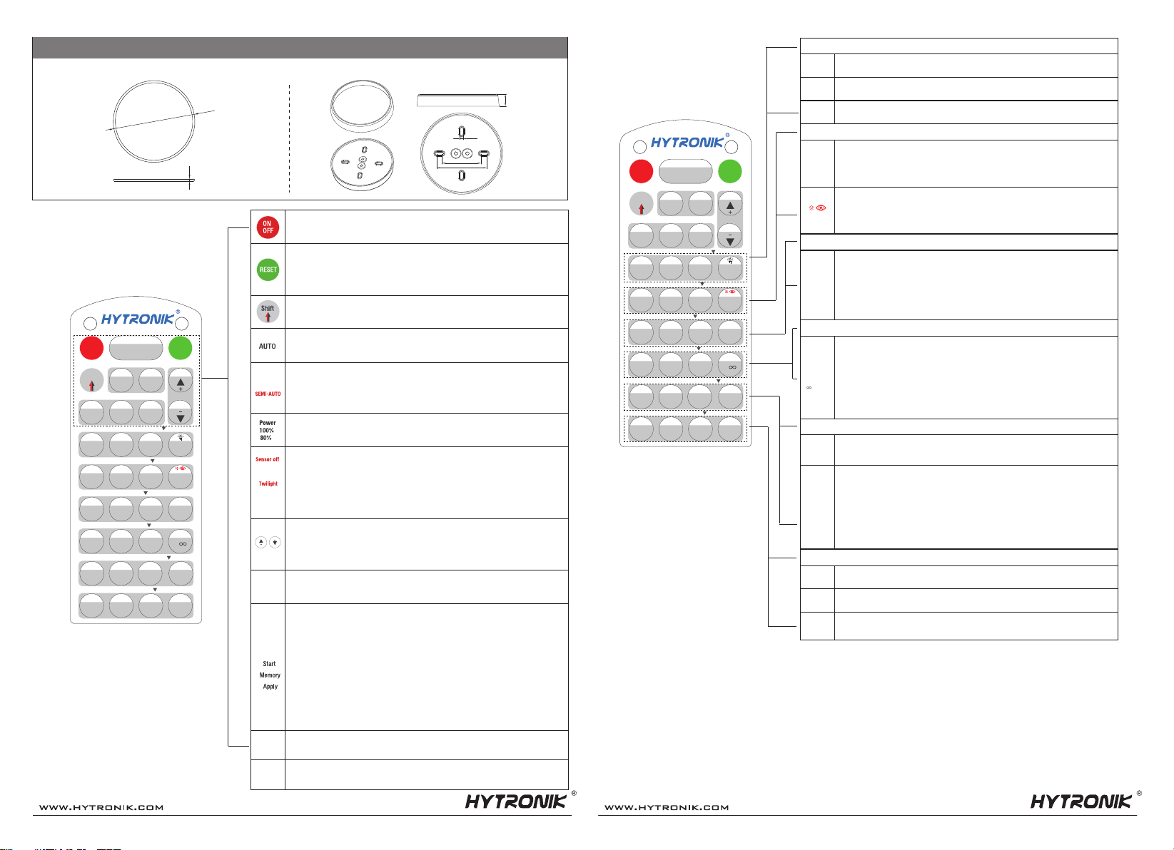
(remote control HRC-11)
6.
HRC-11
Sensor off Twilight
Shift
AUTO
100% 75% 50% 10%
2 Lux
100 Lux
10 Lux
300 Lux
50 Lux
500 Lux
Disable
Ambient
Memory Apply
Test
2 s
30 s
1 min 10 min
5 min 15 min 30 min
0s
10 s 1h
10% 20% 30% 50%
Dual tech & RF mode
SEMI-AUTO
Hold-time
Stand-by time
Stand-by dimming level & Auto-config.
Daylight threshold
Sensitivity & More functions
RX STBY%
PIR
RX 100%
HF HF+PIR HF/PIR
Shift Send
5 min 30 min
20 min
Power
100%
Power
80%
1 min 10 min +
Start
RESET
ON
OFF
24h 30s
12h 4h
Learn
Erase Transmit
Brightness
CCT-
CCT+
Tri-level Harvest Master ×
Exp 1 Exp 2 Lux off
In AUTO /SEMI-AUTO modes, press buttons in zone “hold-time” to set the hold-time at 2s
/ 30s / 1min / 5min / 10min / 15min / 20min / 30min.
Dual tech & RF mode
Press buttons in zone “stand-by time” to set the stand-by period at 0s / 10s / 1min / 5min
/ 10min / 30min / 1h / +∞.
Note: 1. To set stand-by-time at 10s/ 5min / 30min / 1h, press “Shift” button rst.
2. “0s” means on/off control;
3. “+∞” means bi-level control, the xture is 100% on when there is motion detected, and remains at the
stand-by dimming level when no presence after motion hold-time. Only when the stand-by time is set in "+∞" and
the ambient lux level is below the target lux level, the lux will auto-on.
Press the button in zone “stand-by dimming level” to set the stand-by dimming level at 10%
/ 20% / 30% / 50%.
Press buttons in zone “Daylight threshold” to set daylight sensor at 2Lux/ 10Lux / 50Lux
/ 100Lux / 300Lux/500Lux / Disable.
1. Press button “Shift”, the red LED on.
2. Press button “Ambient”, the surrounding lux level is sampled and set as daylight threshold
/ target Lux level.
Note: To set daylight sensor at 100Lux / 300Lux/500Lux , press “Shift” button rst.
Master
100% 75%
50% 10%
Tri-level
Harvest
2 Lux 100 Lux
10 Lux 300 Lux
50 Lux 500 Lux
Disable
Ambient
Test
2 s
30 s
1 min
10 min
5 min
15 min
30 min
20 min
0s 10 s
1h
5 min
30 min
1 min
10 min
+
10% 20%
30% 50%
24h
30s
12h
4h
PIR
HF
HF+PIR
HF/ PIR
Learn
Erase
Transmit
Note: 1. To set hold-time at 30s / 5min / 15min / 30min, press “Shift” button rst.
2. 2s is for testing purpose only, stand-by period and daylight sensor settings are disabled in this mode.
*To exit from Test mode, press button “RESET” or any button in “Hold-time”.
Stand-by time mode
Hold-time mode
Daylight threshold
Sensitivity & More functions
Stand-by dimming level & Auto-cong.
This key is not appliable on this product.
7. Additional Information / Documents
1. Regarding precautions for PIR sensor installation and operation, please kindly refer to www.hytronik.com/download ->knowledge ->PIR Sensors - Precautions for Product Installation and Operation
2. Regarding Hytronik standard guarantee policy, please refer to www.hytronik.com/download ->knowledge ->Hytronik Standard Guarantee Policy
Big silicon water-proof gasket dimension(size:mm)
4.2
48.2
61.8
15.2
Small silicon water-proof gasket dimension(size:mm)
Big and small silicon gasket used to make IP54 degree protection (mounted into HA09 housing for ceiling mount)
2
Ø 78
1.Press button “Shift” ,the red LED on.
2.Select a time period and the sensor will do light level measurement and determine/save
the lowest light level (commission line) with 100% light on, so as to set the target lux level
automatically.
Note:1.Make sure the light level measurement covers the night time.
2.The xture will go into sensor mode after the measurement, all sensor setting remain unchanged.
This key is not appliable on this product.
Subject to change without notice. Subject to change without notice.
Press button “RESET”, all settings go back to default.
The default settings are: Auton mode; DALI Master mode; Hold-time 5min; Daylight sensor
disable; Stand-by time: 10min; Stand-by dimming level: 20%; Maximum Brightness; LED
indication off;
Press button “ON/OFF” to select permanent ON or permanent OFF mode.
* Press button “AUTO”/“RESET” to exit this mode.
For Sensor LED indicator references: Remains on 2s, initiate "Semi-auto" mode from "Auto" mode.
HRC-11
Press button “Shift”, the LED on the top left corner is on to indicate mode selection. All
values / settings in RED are valid for 20 seconds.
For example, to set detection range 100%, daylight threshold Disable, hold-time 5min,
stand-by time +∞, stand-by dimming level 30%, the steps should be:
Press button “Start”, button ”100%”, “Disable”, “Shift”, “5min”, “Shift”, “+∞”, “30%”,
“Memory”. By pointing to the sensor unit(s) and pressing “Apply”, all settings are passed
on the sensor(s).
Press these two buttons to adjust the light output brightness and set a new target lux level.
The daylight sensor can measure ambient daylight level and ignore the LED light, so as to
calculate how much articial light is needed to maintain the target lux level.
Lux off
Exp 1
Exp 2
Press button “AUTO” to initiate automatic mode. The sensor starts working and all settings
remain as before the light is switched ON/OFF;
1. Press button “Shift” ,the red LED on.
2. Press button "SEMI-AUTO" to initiate Semi-auto mode. The sensor is only activated with the
manual press of push switch. To exit this mode, simply press button "SEMI-AUTO" again.
Press buttons in zone “Power out” to select the light output at 80% (at initial 10,000 hours)
or 100%.
1. Press button “Shift”, the red LED on.
2. Press button “Twilight”, the function of movement detection is disabled, but the function
of photocell is still working, and the product becomes a pure dusk/ dawn daylight sensor.
1. Press button “Start” to program.
2. Select the buttons in “Detection range”, “Daylight threshold”, “Hold-time”, “Stand-by
time”, “Stand-by dimming level” to set all parameters.
3. Press button “Memory” to save all the settings programmed in the remote control.
4. Press button “Apply” to set the settings to each sensor unit(s).
"Exp" refer to Expansion, these two buttons are reserved functions and pending future
development.
CCT+
CCT-
To exit from “Twilight” mode, press button “AUTO”/”SEMI-AUTO”/”RESET”.
Sensor off Twilight
Shift
AUTO
100% 75% 50% 10%
2 Lux
100 Lux
10 Lux
300 Lux
50 Lux
500 Lux
Disable
Ambient
Memory Apply
Test
2 s
30 s
1 min 10 min
5 min 15 min 30 min
0s
10 s 1h
10% 20% 30% 50%
Dual tech & RF mode
SEMI-AUTO
Hold-time
Stand-by time
Stand-by dimming level & Auto-config.
Daylight threshold
Sensitivity & More functions
RX STBY%
PIR
RX 100%
HF HF+PIR HF/PIR
Shift Send
5 min 30 min
20 min
Power
100%
Power
80%
1 min 10 min +
Start
RESET
ON
OFF
24h 30s
12h 4h
Learn
Erase Transmit
Brightness
CCT-
CCT+
Tri-level Harvest Master ×
Exp 1 Exp 2 Lux off
This key is not appliable on this product.
Note: “Sensor off” function is not appliable on this product.
This key is not appliable on this product.

Other manuals for HIR27

3

Other Hytronik Accessories manuals

Hytronik HMW12 Quick guide

Hytronik

Hytronik HMW12 Quick guide

Hytronik HMW15 Quick guide

Hytronik

Hytronik HMW15 Quick guide

Hytronik HC005S/BT Quick guide

Hytronik

Hytronik HC005S/BT Quick guide

Hytronik HC005S/I Quick guide

Hytronik

Hytronik HC005S/I Quick guide

Hytronik HC018V User manual

Hytronik

Hytronik HC018V User manual

Hytronik DUAL Sense HIM13 Quick guide

Hytronik

Hytronik DUAL Sense HIM13 Quick guide

Hytronik HIM39/RF Quick guide

Hytronik

Hytronik HIM39/RF Quick guide

Hytronik DualSense HIM11 Quick guide

Hytronik

Hytronik DualSense HIM11 Quick guide

Hytronik HMW31 Quick guide

Hytronik

Hytronik HMW31 Quick guide

Hytronik HMW30 User manual

Hytronik

Hytronik HMW30 User manual

Hytronik HIR28DCVFC Quick guide

Hytronik

Hytronik HIR28DCVFC Quick guide

Hytronik HIR23 Quick guide

Hytronik

Hytronik HIR23 Quick guide

Hytronik HMW39/RF Quick guide

Hytronik

Hytronik HMW39/RF Quick guide

Hytronik HC407VDS User manual

Hytronik

Hytronik HC407VDS User manual

Hytronik HMW31 User manual

Hytronik

Hytronik HMW31 User manual

Hytronik HMW11 Quick guide

Hytronik

Hytronik HMW11 Quick guide

Hytronik HC404VRC-KD User manual

Hytronik

Hytronik HC404VRC-KD User manual

Hytronik HC419V User manual

Hytronik

Hytronik HC419V User manual

Hytronik DUAL SENSE HIM11 Quick guide

Hytronik

Hytronik DUAL SENSE HIM11 Quick guide

Hytronik HC005S/BT Quick guide

Hytronik

Hytronik HC005S/BT Quick guide

Hytronik HMW32 User manual

Hytronik

Hytronik HMW32 User manual

Hytronik HEC7430 User manual

Hytronik

Hytronik HEC7430 User manual

Hytronik HC403VRC-KD/I User manual

Hytronik

Hytronik HC403VRC-KD/I User manual

Hytronik HEC7428 User manual

Hytronik

Hytronik HEC7428 User manual

Popular Accessories manuals by other brands

TEKTELIC Communications Kona All-in-One Home Sensor Series user guide

TEKTELIC Communications

TEKTELIC Communications Kona All-in-One Home Sensor Series user guide

Eurotronic SIROCO quick start guide

Eurotronic

Eurotronic SIROCO quick start guide

Hach POLYMETRON 8350 user manual

Hach

Hach POLYMETRON 8350 user manual

Swann WT83 quick start guide

Swann

Swann WT83 quick start guide

NXP Semiconductors KITMPR121EVM quick start guide

NXP Semiconductors

NXP Semiconductors KITMPR121EVM quick start guide

American Eagle Goals RM54 installation instructions

American Eagle Goals

American Eagle Goals RM54 installation instructions

Dometic ACE AIR PRO 400 operating manual

Dometic

Dometic ACE AIR PRO 400 operating manual

Philips STO2520 Specifications

Philips

Philips STO2520 Specifications

SICK deTec4 Core operating instructions

SICK

SICK deTec4 Core operating instructions

Crestron INETS-IOEX-DOOR-BATT installation guide

Crestron

Crestron INETS-IOEX-DOOR-BATT installation guide

Daktronics TN-2016 DISPLAY MANUAL

Daktronics

Daktronics TN-2016 DISPLAY MANUAL

Dometic 9500E installation instructions

Dometic

Dometic 9500E installation instructions

Risco RWX73M manual

Risco

Risco RWX73M manual

Bogen MIC2X install guide

Bogen

Bogen MIC2X install guide

DAVIS 7709 Solar Power kit installation manual

DAVIS

DAVIS 7709 Solar Power kit installation manual

Mitsubishi Electric PZ-70CSB-E Installation and instruction manual

Mitsubishi Electric

Mitsubishi Electric PZ-70CSB-E Installation and instruction manual

Emmaljunga QUAD Kit instruction manual

Emmaljunga

Emmaljunga QUAD Kit instruction manual

TOPPOINT LT91071 user manual

TOPPOINT

TOPPOINT LT91071 user manual

manuals.online logo
manuals.online logoBrands
  • About & Mission
  • Contact us
  • Privacy Policy
  • Terms and Conditions

Copyright 2025 Manuals.Online. All Rights Reserved.