manuals.online logo
Brands
  1. Home
  2. •
  3. Brands
  4. •
  5. i3 International
  6. •
  7. Security Camera
  8. •
  9. i3 International Ax85 User manual

i3 International Ax85 User manual

SAFETY
When installing your Ax85 camera be sure to avoid:
• excessive heat, such as direct sunlight or heating appliances
• contaminants such as dust and smoke
• strong magnetic elds
• moisture and humidity
• areas with mechanical vibrations
• uorescent lamps or objects that reect light and unstable light sources
• temperatures below -40° C (-40° F) and above 50° C (122° F).
To avoid electrical shock and to preserve the product warranty, DO NOT disassemble the
camera. Refer servicing to qualied personnel only.
POWER SUPPLY
Ensure the supplied voltage meets the power consumption requirements of this camera
before powering the camera on. Incorrect voltage may cause irreparable damage to the
video camera and will effectively void the camera warranty.
Ax85 requires AC24V or PoE+ power.
CLEANING
• For maximum optical clarity, the camera dome or lens must remain clean. Use a soft,
dry cloth to remove nger prints or dust from the dome cover.
• Use a blower to remove dust from the lens.
• Clean the body with a soft, dry cloth. If it is very dirty, use a cloth dampened with a
small quantity of neutral detergent, then wipe dry.
• Do not use volatile solvents such as alcohol, benzene, or thinners, as they may
damage the surface nishes.
PACKAGE CONTENTS
Ensure that the items received match those listed on the order form and the packing slip.
In addition to this manual and a fully assembled camera, the dome camera packing box
includes:
A. Standard RJ45 Connector x2
B. Dessicant x1. Use in all outdoor installations.
Attach to the underside of the camera’s inner
liner/shroud.
C. Round Head Screw (Tapping Type) w/ O-ring x4
D. Plastic Anchor x4
E. Surface Mount template x1
F. Flush Mount template x1
G. Security torx bit x1
H. Long Machine type screws x3
(for Flush Mounting with back box installations)
CAMERA PARTS AND DEFINITIONS
Quick Start Guide
8MP Infrared Outdoor IP Dome Camera w/ Motorized Lens Ax85
i3-TRNG-CAMS-Ax85.indd
Rev. 190911
1. Back box. Camera’s back box comes with six (6) 90% pre-drilled hole dimples.
For surface mounting, complete drilling a minimum of two (2) holes.
2. Camera module / second housing.
3. Tilt bracket with locking screw
4. Inner liner / Shroud. Inner liner is attached to the camera module but can be
partially detached for easier lens adjustment. Attach the desiccant to the inside of
the Inner Liner, without obstructing the lens movement.
5. IR board
6. Screws securing the dome bubble housing to camera module (x3, silver)
7. Dome bubble housing / Dome cover
8. Lexan bubble
9. 3/4” waterproof rubber plug. For best waterproof performance, use a network cable
5mm or more in diameter. To maintain IP67 waterproof rating, use sealant on the
threads during installation. If using the side conduit hole, replace the rubber plug
with the metal plug from the side conduit. Rubber plug is not recommended for use
in the side conduit hole.
10. 3/4” side conduit hole with metal plug. If using the side conduit hole, remove the
metal plug and use it instead of the rubber plug in the top conduit hole. To maintain
IP67 waterproof rating, use sealant on the threads during installation.
11. Six (6) 90% pre-drilled hole dimples.
12. Reset pin-hole button. Press for 1 second to reboot the camera.
13. Default pin-hole button. Press for 6 seconds to restore camera settings to factory
defaults.
14. Service Video Output RCA Port. Connect an analog service monitor for a live image
output preview.
15. Screws attaching camera module to the back box (x3, silver)
16. Screws to engage locking arms (x2, black)
17. Micro SD Card slot for on-camera video storage. (microSD card sold separately)
Lens Direction
GUIDE PATTERN
Scan this QR code or visit www.i3international.com to
view and download the full User Manual for this camera. Also
available for download is the AnnexxusConfigurationTool
or ACT program used to locate and congure your cameras
with your SRX-Pro software. This program is already installed
in SRX-Pro v3.3.3.69 and higher. Please contact our Technical
Support team if you have any questions or concerns regarding
camera installation or you require software services or
support. Technical support can be reached by email at:
[email protected] or by phone toll free
1.877.877.7241.
QR Code to Complete
User Manual / ACT
1
2
5
3
4
6
7
8
FG
GUIDE PATTERN
Cut Line
Camera Outline
A
CD
H
E
B
10 11
9
9
63 mm (2.5”)
63 mm (2.5”)
84 mm (3.3”) 147 mm (5¾”)
68 mm (2.67”)
94 mm (3.7”)
158 mm (6¼”)
DEFAULT
RESET
MONITOR
RESET MONITOR
DEFAULT
12 13
14
15 15
15
16 16
17
*Important: For the security of your camera and of all connected devices,
i3 International recommends that you change your camera’s default administrative
password in the camera’s User Management setup tab. Keep your passwords
secure.
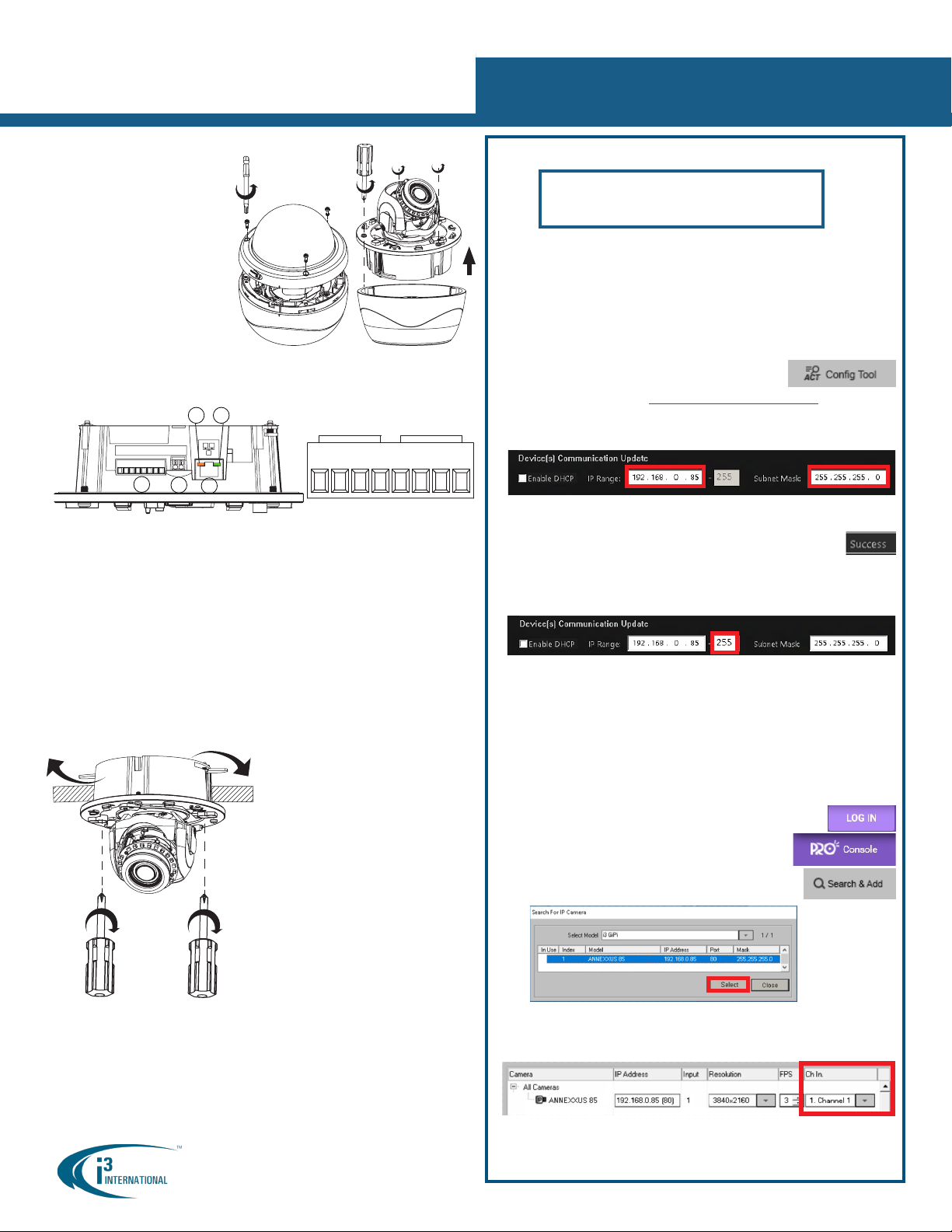
Change your Annexxus camera’s default IP Address:
Annexxus Cameras cannot share an IP address, each camera requires its own
unique IP address.
1. Connect your Annexxus camera to the Gigabit switch.
2. On your i3 NVR, launch i3 Annexxus Conguration Tool (ACT). ACT can be
accessed from the Windows Start menu or from the IP
Camera setup tab (ACT Config Tool button)
You can download and install the latest ACT installation
package from i3 website: https://i3international.com/download
3. Select your Annexxus camera in the ACT list.
4. Enter the new IP address and Subnet Mask of the camera in the Device(s)
Communication Update area.
5. Click Update and then Yes in the conrmation window.
Tip: New IP address must match the IP range of LAN or NVR’s NIC1.
6. Wait a few moments for a “Success” message in the Result eld.
Repeat Steps 1-6 for all detected Annexxus cameras OR
7. Assign IP range to multiple cameras by selecting two or more cameras in ACT,
then entering the starting IP address and the nal IP octet for your IP range.
Click Update and then Yes in the conrmation window.
Wait until “Success” message is shown for all selected cameras.
Ensure you can connect to your camera(s) using its new IP Address:
1. Open an Internet browser window and enter the new IP Address you have just
assigned to your Annexxus camera in Step 4 (or 7).
2. Enter the camera User Name and Password in the pop-up login window.
3. Annexxus camera interface will be displayed in the Internet Explorer window.
You should be able to see the camera image on the screen. If you do not see
the camera image on the screen, call i3 International technical support team
for troubleshooting tips: 1.877.877.7241
Add your Annexxus camera to IP Camera tab in SRX-Pro Server:
1. (SRX-Pro Service Users) Click LOG IN in SRX-Pro Service
Monitor, enter your credentials and click LOGIN.
2. Click PRO Console button to launch Pro Console.
3. Go to Setup -> IP Camera tab.
4. Click the Search & Add button to display connected
Annexxus cameras.
5. Select the detected camera in the list and click Select.
6. In the Select IP Camera window, enter camera’s User Name and Password
and click Add.
Selected camera will be added to the Camera list.
7. Assign the camera to the SRX-Pro video channel in the Ch In. column.
Your Annexxus camera is now connected to SRX-Pro Server and is ready to record.
Change resolution and frame rate for the Annexxus camera in the IP Camera tab
menu or via Web Setup.
DISASSEMBLING THE CAMERA
I/O CONNECTORS
Ax85 IP Dome Camera
QUICK START GUIDE
1. Use the provided security
Torx key to loosen three silver
screws securing the dome
bubble housing to camera
module (#6). Do not completely
remove the screws from the
dome bubble. Set the dome
bubble aside.
2. Next, loosen three silver screws
attaching camera to the back
box (#15).
3. Remove camera’s back box and
set aside.
Once the camera’s back box has been removed, the Ax85 input/output connectors will
be revealed on the camera’s module, including RJ45 Ethernet/PoE+ connector, Audio and
Alarm connectors and AC24V power port.
1. Audio and Alarm I/O connectors. Ax85 is compatible with i3 Mo-1 microphones.
2. AC 24V Port. Connect AC 24V power supply.
3. RJ45 Ethernet Connector / PoE+. Connect RJ45 network cable for Ethernet/Internet
connectivity. PoE+ (Power over Ethernet) is supported.
Caution: Do not apply power until the camera is properly and securely mounted.
4. Orange LED. Flashing orange LED indicates data transmission between the camera
and the Internet.
5. Green LED. Solid green LED indicates a current live connection.
FLUSH MOUNTING w/LOCKING ARMS
Note: Based on installation location and surface type, supplied screws and anchors may
not be adequate. Use this installation method for indoor installations only. This method
is suitable for drywall and T-bar installations only. See complete manual for additional
mounting options. 1. Use the Flush Mounting Template to cut
a hole in the mounting surface.
2. Disassemble the camera. Remove
camera’s back box and set aside. It will
not be used in this type of installation.
3. Insert the microSD card into the
microSD slot on the camera module (if
using).
4. Insert the camera into the cut hole in
the surface.
5. Feed all cables through the opening in
the mounting surface and connect to the
camera. Do not apply power until the
installation is complete.
6. Use a Phillips screwdriver to turn two
black-coloured screws on the camera
module clockwise to engage the locking
arms. Tighten the arms securely against the
mounting surface.
7. Adjust the lens angle by rotating and
panning the camera lens base. Lift off
the camera liner for easy lens position
adjustment. Do not over-rotate the camera
lens beyond the stop point to avoid damage
to the camera.
8. Once the desired view is achieved, replace camera liner until it snaps back into place.
9. Replace the camera’s dome bubble on top of the camera module. Use the red dots on
both modules for easy alignment.
10. Use the supplied Torx bit to re-tighten 3 silver screws securing the dome bubble
housing to the camera module.
123
4 5
1.866.840.0004
www.i3international.com
Rev. 190911
i3 INTERNATIONAL INC.
Audio In
GND
GND
GND
AudioOut
AlarmCOM
Alarm out
Alarm in
24V
~~
AudioIn
GND
GND
GND
AudioOut
Alarmin
AlarmCOM
Alarmout
Audio In
Audio Out
GND
Alarm COM
Alarm out
GND
Alarm in
Audio In/Out
GND
Alarm In/Out
CONNECT CAMERA TO i3 SRX-PRO SERVER
Camera’s default IP address: 192.0.0.16.
Camera’s default Subnet mask address: 255.255.255.0.
Credentials*: Login - i3admin / Password - i3admin

Other i3 International Security Camera manuals

i3 International i3F416U User manual

i3 International

i3 International i3F416U User manual

i3 International Ax68R User manual

i3 International

i3 International Ax68R User manual

i3 International Ax32VD14 User manual

i3 International

i3 International Ax32VD14 User manual

i3 International Am42 Series User manual

i3 International

i3 International Am42 Series User manual

i3 International Annexxus 52C User manual

i3 International

i3 International Annexxus 52C User manual

i3 International Am52R User manual

i3 International

i3 International Am52R User manual

i3 International M75 User manual

i3 International

i3 International M75 User manual

i3 International C-AX401C1MN User manual

i3 International

i3 International C-AX401C1MN User manual

i3 International DB78BB User manual

i3 International

i3 International DB78BB User manual

i3 International Ax45RM series User manual

i3 International

i3 International Ax45RM series User manual

i3 International Ax61 series User manual

i3 International

i3 International Ax61 series User manual

i3 International Ax61 series Operating and maintenance instructions

i3 International

i3 International Ax61 series Operating and maintenance instructions

i3 International A 65W Series User manual

i3 International

i3 International A 65W Series User manual

i3 International Di210 User manual

i3 International

i3 International Di210 User manual

i3 International Ax47R series User manual

i3 International

i3 International Ax47R series User manual

i3 International Ax52D2MV User manual

i3 International

i3 International Ax52D2MV User manual

i3 International Di721 User manual

i3 International

i3 International Di721 User manual

i3 International C-AX401C1M User manual

i3 International

i3 International C-AX401C1M User manual

i3 International i3-B731 User manual

i3 International

i3 International i3-B731 User manual

i3 International Ax40W2 series User manual

i3 International

i3 International Ax40W2 series User manual

i3 International M71 User manual

i3 International

i3 International M71 User manual

i3 International Ax83C User manual

i3 International

i3 International Ax83C User manual

i3 International Ax49D User manual

i3 International

i3 International Ax49D User manual

i3 International Di721 User manual

i3 International

i3 International Di721 User manual

Popular Security Camera manuals by other brands

Alecto DVC136IP user manual

Alecto

Alecto DVC136IP user manual

ADT A-CE6TW2812UW instruction manual

ADT

ADT A-CE6TW2812UW instruction manual

ATV C700TDN instruction manual

ATV

ATV C700TDN instruction manual

Dahua TPC-PT8620A-B quick start guide

Dahua

Dahua TPC-PT8620A-B quick start guide

Sony 540TVL instruction manual

Sony

Sony 540TVL instruction manual

Brickcom CB-500A Series user manual

Brickcom

Brickcom CB-500A Series user manual

Lorex VQ1130R installation instructions

Lorex

Lorex VQ1130R installation instructions

Optiview LPRHD2M-550M Setup guide

Optiview

Optiview LPRHD2M-550M Setup guide

Novus NVIP-5DN3625AV/940IR-1P user manual

Novus

Novus NVIP-5DN3625AV/940IR-1P user manual

Samsung SVD-4120A Quick install guide

Samsung

Samsung SVD-4120A Quick install guide

SHARX SECURITY HTNC5404M quick start guide

SHARX SECURITY

SHARX SECURITY HTNC5404M quick start guide

Amcrest IP2M-852EB user manual

Amcrest

Amcrest IP2M-852EB user manual

Ikegami IPD-BX100 Series Specifications

Ikegami

Ikegami IPD-BX100 Series Specifications

EverFocus EQN22 Series user manual

EverFocus

EverFocus EQN22 Series user manual

Eyemax DO-632V manual

Eyemax

Eyemax DO-632V manual

GeoVision 84-VD870000-001U user manual

GeoVision

GeoVision 84-VD870000-001U user manual

Digital Watchdog MEGAPIX DWC-MF5Wi4TWDMP quick start guide

Digital Watchdog

Digital Watchdog MEGAPIX DWC-MF5Wi4TWDMP quick start guide

Dynamic CCTV DTV-VLDpro-W6 user manual

Dynamic CCTV

Dynamic CCTV DTV-VLDpro-W6 user manual

manuals.online logo
manuals.online logoBrands
  • About & Mission
  • Contact us
  • Privacy Policy
  • Terms and Conditions

Copyright 2025 Manuals.Online. All Rights Reserved.