manuals.online logo
Brands
  1. Home
  2. •
  3. Brands
  4. •
  5. IAI
  6. •
  7. Controllers
  8. •
  9. IAI RCP6 Series User manual

IAI RCP6 Series User manual

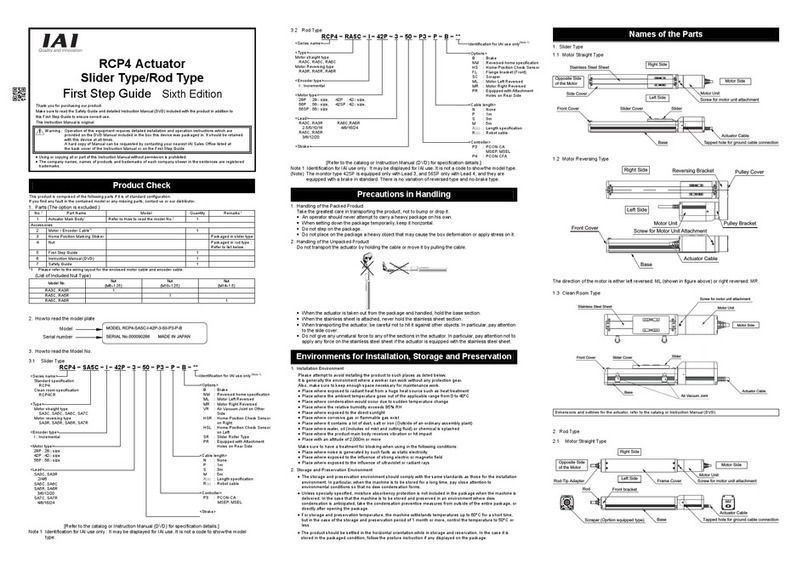
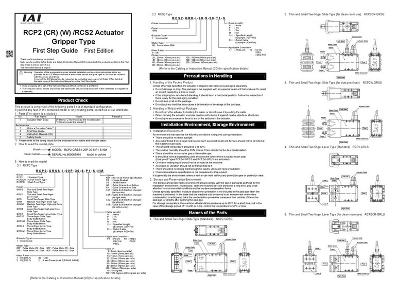
RCP6 Actuator
Gripper Type
First Step Guide Second Edition
Thank you for purchasing our product.
Make sure to read the Safety Guide and detailed Instruction Manual (CD/DVD) included with the product in addition to
this First Step Guide to ensure correct use.
This Instruction Manual is original.
Using or copying all or part of this Instruction Manual without permission is prohibited.
The company names, names of products and trademarks of each company shown in the sentences are registered
trademarks.
This product is comprised of the following parts if it is of standard configuration.
If you find any fault in the contained model or any missing parts, contact us or our distributor.
1. Parts (The option is excluded.)
No. Part Name Model Quantit
y
Remarks
1
Actuator
Refer to “How to Read the Model
Nameplate” and “How to Read the Model
Number.”
1
Accessories
2 Motor • encoder
cables (Note1)
1
3 First Step Guide 1
4 Instruction Manual
(DVD)
1
5 Safety Guide 1
Note 1 Please refer to the wiring layout for the enclosed motor cable and encoder cable.
2. How to Read the Model Plate
3. How to Read the Model No.
3.1 Thin Type Gripper
Note 1 Identification for IAI use only: It may be displayed for IAI use. It is not a code to show the model type.
[Refer to the catalog or Instruction Manual (DVD) for specification details.]
3.2 Long Stroke Gripper
RCP6-GRST6C-WA-42P-2-180-P3-P-B-**
<Series>
Standard Specification <Options>
RCP6 B : With Brake
Built-in Controller Specification NM : Reversed-home Specification
RCP6S CJT : Cable Exit Direction Changed
(Top) (Top)
<Type> CJR : Cable Exit Direction Changed
Motor Straight Type (Right)
GRST6C CJL : Cable Exit Direction Changed
GRST7C (Left)
Motor Reversing Type CJB : Cable Exit Direction Changed
GRST6R (Bottom)
GRST7R CJO : Cable Exit Direction Changed
(Outward)
<Encoder Type> ML : Motor Unit Left-Reversed
WA : Battery-less Absolute Direction
MR : Motor Unit Right-Reversed
<Motor Type> Direction
42P : 42□size SS : Slider Spacer
56P : 56□size SR : Slider Roller Specification
MJF : Slider Attachment Installation
<Lead> Tool
2/8
<Cable Length>
<Stroke> N : None
GRST6C, GRST6R P : 1m
180 (One side 90), 230 (One side 115) S : 3m
RGST7C, GRST7R M : 5m
210 (One side 105), 260 (One side 130) X□□ : Length Specification
R□□ : Robot Cable
Standard Specification
<Applicable Controllers>
P3 : PCON-CB/CGB, PCON-CYB/PLB/POB
MCON-C/CG/LC/LCG, MSEL-PC/PG
P5 : RCON-PC
RCM-P6PC
Built-in Controller Specification
<I/O Type>
SE : SIO Type
Precautions in Handling
1. Handling the Packed Unit
Do not damage or drop. The package is not applied with any special treatment that enables it to resist
an impact caused by a drop or crash.
Transport a heavy package with at least more than two operators. Consider an appropriate method for
transportation.
Keep the unit in a horizontal orientation when placing it on the ground or transporting. Follow the
instruction if there is any for the packaging condition.
Do not step or sit on the package.
Do not put any load that may cause a deformation or breakage of the package.
2. Handling the Actuator After Unpacking
Do not carry the actuator by its motor unit or its cable or attempt to move it by pulling the
cable.
Hold the frame or motor cover section of the body when transporting the actuator main body.
Do not hit or drop the actuator during transportation.
Do not attempt to force any part of the actuator. Do not apply excess force especially on the fingers and
finger guide.

Environments for Installation, Storage and Preservation
Usage is possible in environments of pollution degree 3 or equivalent.
1. Installation Environment
The actuator should be installed in a location other than those specified below.
Also provide sufficient work space required for maintenance inspection.
Where the actuator receives radiant heat from strong heat sources such as heat treatment furnaces
Where the ambient temperature exceeds the range of 0 to 40C
Where the temperature changes rapidly and condensation occurs
Where relative humidity smaller than 20% or larger than 85%RH
Where the actuator receives direct sunlight
Where the actuator is exposed to corrosive or combustible gases
Where the ambient air contains a large amount of powder dust, salt or iron (at level exceeding what is
normally expected in an assembly plant)
Where the actuator is subject to splashed water, oil (including oil mist or cutting fluid) or chemical
solutions
Where the actuator receives impact or vibration
Place with an altitude of 2,000m or more
If the actuator is used in any of the following locations, provide sufficient shielding measures:
Where noise generates due to static electricity, etc.
Where the actuator is subject to a strong electric or magnetic field
Where the actuator is subject to ultraviolet ray or radiation
Names of the Parts
1. Thin Type Gripper GTRT7A/GRT7B
End Cover
(Cable) Frame
End Cover (Belt)
Guide
Finger Opening and
Closing Screw
Hole Caps Actuator Cable
Finger Opening and
Closing Screw
Fingers
[For the details of dimensions and outlines, refer to the catalog or Instruction Manual (DVD).]
2. Long Stroke Gripper GRST6C/GRST7C/GRST6R/GRST7R
2.1 Standard Specification Motor Straight Type
2.2 Built-in Controller Specification Motor Straight Type
Product Check
MODEL RCP6-GRT7A-WA-28P-1-30-P3-P-NM
SERIAL No.000090266 MADE IN JAPAN
RCP6
–
GRT7
A
-W
A
- 28P - 1 - 30 - P3
–
P
–
NM - * *
Series
<Type>
Slide Type
GRT7A
GRT7B
<Encoder Type>
WA : Battery-less absolute
<Motor Type>
28P : 28□size
<Gear Ratio Pattern>
GRT7A
1 : Feed screw lead length 1.5mm
Pulley deceleration ratio 1.5
GRT7B
1 : Feed screw lead length 2mm
Pulley deceleration ratio 1.25
2 : Feed screw lead length 2mm
Pulley deceleration ratio 2.5
<Stroke>
Identification for IAI use only
(Note1)
<Options>
AC1 :
Actuator cable 1m specification
AC2 :
Actuator cable 2m specification
AC3 :
Actuator cable 3m specification
NM :
Reversed-home specification
CJTB :
Rear cable ejection to top side
CJLB :
Rear cable ejection to left side
CJRB:
Rear cable ejection to right sid
e
CJBB :
Rear cable ejection to bottom
side
CJTS :
Side cable ejection to top side
CJLS :
Side cable ejection to left side
CJRS:
Side cable ejection to right side
CJBS :
Side cable ejection to bottom
side
<Cable Length>
N : None
P : 1m
S : 3m
M : 5m
X□□ : Length specification
R□□ : Robot cable
<Controller>
P3 : PCON-CB/CGB
PCON-CYB/PLB/POB
MCON-C/CG/LC/LCG
MSEL-PC/PG
P5 : RCON-PC
RCM-P6PC
Model
Serial numbe
r
Warning: Operation of this equipment requires detailed installation and operation instructions which are
provided on the CD/DVD Manual included in the box this device was packaged in. It should be
retained with this device at all times.
A hard copy of Manual can be requested by contacting your nearest IAI Sales Office listed at
the back cove
r
of the Instruction Manual or on the First Step Guide.
Identification for IAI use only
(Note 1)
2. Storage • Preservation Environment
The storage and preservation environment should comply with the same standards as those for the
installation environment. In particular, when the machine is to be stored for a long time, pay close
attention to environmental conditions so that no dew condensation forms.
Unless specially specified, moisture absorbency protection is not included in the package when the
machine is delivered. In the case that the machine is to be stored and preserved in an environment
where dew condensation is anticipated, take the condensation preventive measures from outside of
the entire package, or directly after opening the package.
For storage and preservation temperature, the machine withstands temperatures up to 60C for a
short time, but in the case of the storage and preservation period of 1 month or more, control the
temperature to 50C or less.
Storage and preservation should be performed in the horizontal condition. In the case it is stored in the
packaged condition, follow the posture instruction if any displayed on the package.
Note 1 Identification for IAI use onl
y
:
It may be displayed for IAI use. It is not a code to show the model
type.
[Refer to the catalog or Instruction Manual (DVD) for specification details.]
2.3 Standard Specification Motor Reversing Type
2.4 Built-in Controller Specification Motor Reversing Type
Attachment
Refer to the Instruction Manual (DVD) for the attachments of the actuator and loads.
[Precautions for Attachments]
No. Item Precautions
1 Installation  Long Stroke Gripper, it may cause slackness or misalignment of the
stainless steel sheet. Continued usage in this orientation may lead to
damage to the stainless steel sheet. Check the actuator daily and , make
installation adjustment of the stainless steel sheet. (Refer to the
maintenance section of instruction manual (DVD) for the “Procedure for
Stainless Steel Sheet Adjustment”])
2 Attachment Surface Make sure that the surface to install the actuator and that used as the
datum are a well-finished machined surface or one that possesses an
accuracy equivalent to it.
Ensure a room for maintenance work.
3 Bolt to be used  For the bolts to be used, a high-tensile bolt complying with ISO-10.9 or
more is recommended.
 If using the tapped holes, use screws with the thread length dimension
being less than the effective depth of the holes.
 For the actuator mounting, use a bolt with the dimension of its effective
mating length to the tapped hole is as stated below.
If tapped hole on steel thread length same as nominal diameter
If tapped hole on aluminum maximum depth tapped hole
For a tapped hole with its depth at 1.8
times or more of the nominal diameter,
have 1.8 times or more of the nominal
diameter
4 Tightening Torque  Please follow the specification values stated in the Instruction Manual
(DVD) for the tightening torque.
Failure to do so may cause an operation problem.
5 Allowable Moment Please follow the specification values stated in the Instruction Manual
(DVD) for the allowable moment.
Applying load exceeding the allowable moment may cause a drop in the
product life.
No. Item Precautions
6 Stainless Steel Sheet Do not attempt to hold the stainless steel sheet on the long stroke
gripper directly with hand.
Also, pay attention not to make a dent mark on the stainless steel sheet.
As the stainless steel sheet is thin, it is easy to get a dent mark or
scratch. Using sheet with damage may cause it get broken.
Wipe off all dust and metal powers when they get on the stainless steel
sheet. Operation with stainless steel sheet with foreign obstacles on
could cause damage, waving or looseness on the sheet when it gets
pinched inside the fingers.
Do not work in an ambient that contain dust and metal powers.
Wiring
For the controller, only the dedicated controller manufactured by our company can be used.
Using an undedicated controller may cause an accident such as burnout, combustion or heat generation.
Use the dedicated cable enclosed in the package when connecting the actuator and the controller.
[Prohibited Items in the Cable Processing]
Do not pull or bend forcibly the cable so as to give any extra load or tension to the cable.
Do not process the cable to extend or shortening by means of cutting out, combination or connecting
with another cable.
Do not bend the cable in the area from the connector tip inward to 150mm on both ends.
CB-CAN-MPA□□□, CB-CAN-MPA□□□-RB, CB-ADPC-MPA-□□□, CB-ADPC-MPA-□□□-RB
150mm 150mm
Do not let the cable flex at a single point.
Do not let the cable bend, kink or twist.
Do not pull the cable with a strong force
Do not let the cable receive a turning force at a single point.
Do not pinch, drop a heavy object onto or cut the cable.
When fixing the cable, provide a moderate slack and do not tension it too tight.
Separate the I/O line, communication line and power line from each other.
Do not store in the same duct.
RCP6-×× r 50mm
or more
RCP6-×× r 50mm
or more
Follow the instructions below when using a cable track.
If there is an indication to the cable for the space factor in a cable track, refer to the wiring instruction given by the
supplier when storing the cable in the cable track.
Avoid the cables to get twined or twisted in the cable track, and also to have the cables move freely and do not tie them
up. (Arrange the wiring so the cables are not to be pulled when bent.)
Do not pile up cables. It may cause faster abrasion of the sheaths or cable breakage.
Note:
When the cable is connected or disconnected, make sure to turn off the power to the controller. When the cable is
connected or disconnected with the controller power turned ON, it might cause a malfunction of the actuator and result
in a serious injury or damage to the machinery.
When the connector connection is not correct, it would be dangerous because of a malfunction of the actuator. Make
sure to confirm that the connector is connected correctly.
Head Office: 577-1 Obane Shimizu-KU Shizuoka City Shizuoka 424-0103, Japan
TEL +81-54-364-5105 FAX +81-54-364-2589
website: www.iai-robot.co.jp/
Ober der Röth 4, D-65824 Schwalbach am Taunus, Germany
TEL 06196-88950 FAX 06196-889524
SHANGHAI JIAHUA BUSINESS CENTER A8-303, 808, Hongqiao Rd. Shanghai 200030, China
TEL 021-6448-4753 FAX 021-6448-3992
website: www.iai-robot.com
Technical Support available in USA, Europe and China
Head Office: 2690 W. 237th Street, Torrance, CA 90505
TEL (310) 891-6015 FAX (310) 891-0815
Chicago Office: 110 East State Parkway, Schaumburg, IL 60173
TEL(847) 908-1400 FAX (847) 908-1399
TEL (678) 354-9470 FAX (678) 354-9471
website: www.intelligentactuator.com
Atlanta Office: 1220 Kennestone Circle, Suite 108, Marietta, GA 30066
825 PhairojKijja Tower 12th Floor, Bangna-Trad RD., Bangna, Bangna, Bangkok 10260, Thailand
TEL +66-2-361-4458 FAX +66-2-361-4456
Manual No.: ME3768-2A

Other manuals for RCP6 Series

1

Other IAI Controllers manuals

IAI ssel User manual

IAI

IAI ssel User manual

IAI XSEL-R User manual

IAI

IAI XSEL-R User manual

IAI Rcon User manual

IAI

IAI Rcon User manual

IAI ACON-C Series User manual

IAI

IAI ACON-C Series User manual

IAI ERC Series User manual

IAI

IAI ERC Series User manual

IAI ELECYLINDER EC GD3 Instruction Manual

IAI

IAI ELECYLINDER EC GD3 Instruction Manual

IAI SCON-CGAL User manual

IAI

IAI SCON-CGAL User manual

IAI RoboNet User manual

IAI

IAI RoboNet User manual

IAI ELECYLINDER EC-WS10 R Series User manual

IAI

IAI ELECYLINDER EC-WS10 R Series User manual

IAI ROBO Cylinder RCS4- SA4C User manual

IAI

IAI ROBO Cylinder RCS4- SA4C User manual

IAI ACON-C User manual

IAI

IAI ACON-C User manual

IAI PSEL User manual

IAI

IAI PSEL User manual

IAI X-SEL QX User manual

IAI

IAI X-SEL QX User manual

IAI MSCON User manual

IAI

IAI MSCON User manual

IAI ssel User manual

IAI

IAI ssel User manual

IAI SEL User manual

IAI

IAI SEL User manual

IAI ASEP User manual

IAI

IAI ASEP User manual

IAI X-SEL User manual

IAI

IAI X-SEL User manual

IAI RCD Series User manual

IAI

IAI RCD Series User manual

IAI MCON-C User manual

IAI

IAI MCON-C User manual

IAI PCON-C User manual

IAI

IAI PCON-C User manual

IAI X-SEL User manual

IAI

IAI X-SEL User manual

IAI ASEP User manual

IAI

IAI ASEP User manual

IAI X-SEL User manual

IAI

IAI X-SEL User manual

Popular Controllers manuals by other brands

Areca ARC-1883 Series user guide

Areca

Areca ARC-1883 Series user guide

Omron NX1P Programming manual

Omron

Omron NX1P Programming manual

Graco Series A Instructions - parts

Graco

Graco Series A Instructions - parts

Guardian Controls International RCC20 Series Operation and setup guide

Guardian Controls International

Guardian Controls International RCC20 Series Operation and setup guide

KIPI ecoMAX860P3-C Installation and operating manual

KIPI

KIPI ecoMAX860P3-C Installation and operating manual

Viessmann Commander 5300 quick start

Viessmann

Viessmann Commander 5300 quick start

intelliConsole IC200 quick start guide

intelliConsole

intelliConsole IC200 quick start guide

Exlar Tritex installation manual

Exlar

Exlar Tritex installation manual

HomeMatic HM-LC-BI1PBU-FM Installation and operating manual

HomeMatic

HomeMatic HM-LC-BI1PBU-FM Installation and operating manual

DOTECH FX3S Series user manual

DOTECH

DOTECH FX3S Series user manual

Extron electronics HD CTL 100 Setup guide

Extron electronics

Extron electronics HD CTL 100 Setup guide

Delta Tau PBC Series Hardware reference guide

Delta Tau

Delta Tau PBC Series Hardware reference guide

Welger E-LINK RP 235 operating manual

Welger

Welger E-LINK RP 235 operating manual

Nobile NobiLED 5920/RGB user manual

Nobile

Nobile NobiLED 5920/RGB user manual

Honeywell ML7984B user manual

Honeywell

Honeywell ML7984B user manual

SanRex CALPOTE UG Series instruction manual

SanRex

SanRex CALPOTE UG Series instruction manual

Rockford Fosgate PMX-RGB manual

Rockford Fosgate

Rockford Fosgate PMX-RGB manual

Binks 85-214 Service manual

Binks

Binks 85-214 Service manual

manuals.online logo
manuals.online logoBrands
  • About & Mission
  • Contact us
  • Privacy Policy
  • Terms and Conditions

Copyright 2025 Manuals.Online. All Rights Reserved.