WPI Nanoliter 2000 User manual

Nanoliter 2000
Microprocessor controlled nanoliter injection
World Precision Instruments
INSTRUCTION MANUAL
Serial No._____________________
092512
www.wpiinc.com


Nanoliter 2000
World Precision Instruments iii
Copyright © 2012 by World Precision Instruments, Inc. All rights reserved. No part of this publication
may be reproduced or translated into any language, in any form, without prior written permission of
World Precision Instruments, Inc.
CONTENTS
ABOUT THIS MANUAL .....................................................................................................1
INTRODUCTION..................................................................................................................2
General Notes.................................................................................................................2
Parts List............................................................................................................................2
Unpacking........................................................................................................................3
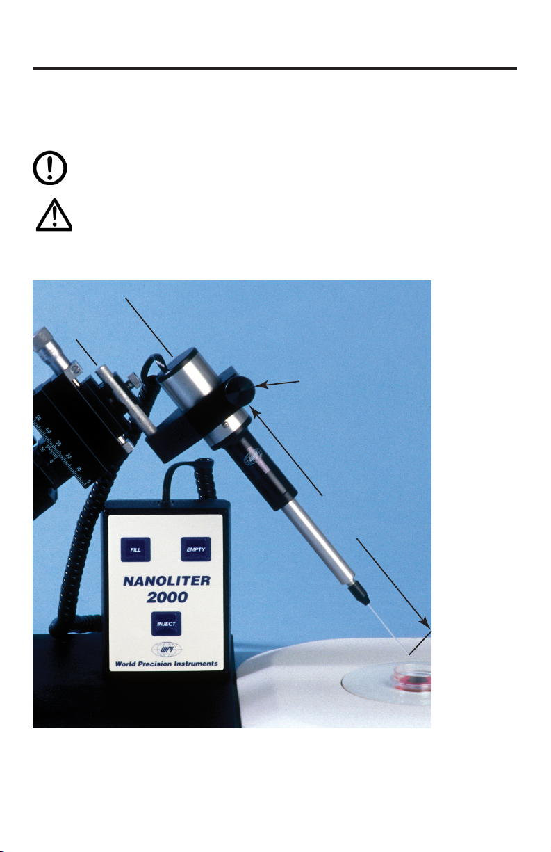
INSTRUMENT DESCRIPTION..........................................................................................4
Instrument Description ................................................................................................4
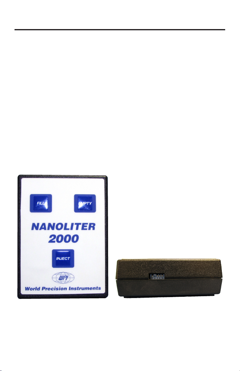
Controller Buttons ....................................................................................................5
Plunger in “HOME” Position..................................................................................6
OPERATING INSTRUCTIONS...........................................................................................7
Micropipette Pulling......................................................................................................7
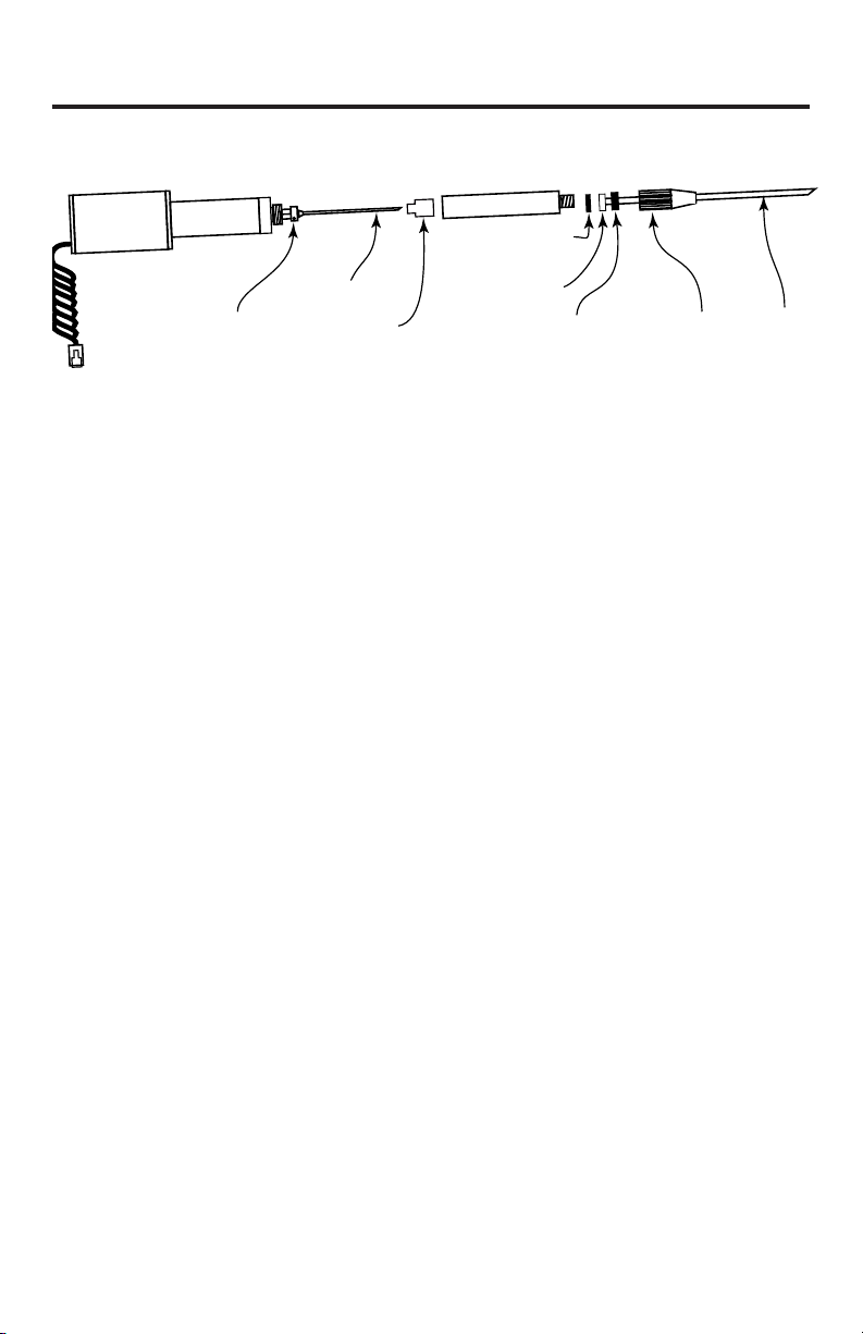
Securing the Micropipette to the Injector..............................................................7
Micropipette Filling Techniques...........................................................................8
Back Filling..................................................................................................................8
Front Filling.................................................................................................................9
Typical Technique.....................................................................................................9
Injecting ...........................................................................................................................9
Setting the Aliquot Volume and Injection Speed.............................................10
MAINTENANCE.................................................................................................................11
Replacing O-Rings ...................................................................................................... 11
Replacing the Wire Plunger ....................................................................................11
Cleaning Recommendations...................................................................................12
OPTIONAL ACCESSORIES............................................................................................. 12
TROUBLESHOOTING...................................................................................................... 13
SPECIFICATIONS............................................................................................................... 13
APPENDIX: NANOLITER 2000/MICRO4 VOLUME SETTINGS......................... 14
Setting the Correct Volume on the Micro4........................................................15
INDEX ..................................................................................................................................17
DECLARATION OF CONFORMITY..............................................................................18
WARRANTY .......................................................................................................................19
Claims and Returns....................................................................................................19
Repairs............................................................................................................................19

iv World Precision Instruments

Nanoliter 2000
World Precision Instruments 1
ABOUT THIS MANUAL
The following symbols are used in this guide:
This symbol indicates a CAUTION. Cautions warn against actions that
can cause damage to equipment. Please read these carefully.
This symbol indicates a WARNING. Warnings alert you to actions that
can cause personal injury or pose a physical threat. Please read these
carefully.
NOTES and TIPS contain helpful information.
40mm
Reversing mount 180º will
reduce manipulator-to-tip
distance by 10cm.
Mounting Rod:
8.2Ø x 50mm
13.5cm
2.5–7.5cm
Total volume in pipette:
1~3” = 4.9–17.4µL
Universal
Adapter for Nanoliter
Injector
Fig. 1–Nanoliter 2000 setup. Micromanipulator is not included .

2 World Precision Instruments
INTRODUCTION
The Nanoliter 2000 microinjection system provides you with the capability
to inject liquids in discrete aliquots ranging from 2.3nL to 69nL. The
Nanoliter Injector utilizes a stainless steel plunger to create a mechanical
displacement of fluid within a micropipette, thus pushing the contents out
through the pipette tip.
General Notes
• The wire plungers on all injectors have a point on one end. This wire
can be reversed if a blunt end is desired. The point should allow bubbles
in the oil to escape when backfilling tips.
• The preferred tip opening size for Xenopus injection is about 20µm.
Some researchers report using 30µm tips with no increase in mortality.
• Injections of 25nL or less generally require smaller tips, normally 10µm.
• A broken tip is preferable for oocyte injection. Sharp polished tips tend
to deflect.
• An excellent reference for all procedures involving the Xenopus oocyte
is Kay, B. and H. Peng, “Xenopus Iaevis: Practical Uses in Cell and
Molecular Biology.” Methods in Cell Biology, Vol. 36, Academic Press.
Parts List
After unpacking, verify that there is no visible damage to the instrument.
Verify that all items are included:
(1) Injector head
(1) Control unit
(1) Power supply
(1) 500778 Universal Adapter for Nanoliter Injector
(2) Capillary glass vials
(1) 3.5” capillaries, 100 pieces
(2) 7.0” capillaries, 100 pieces
(1) Replacement O-ring kit, standard
(2) Allen wrenches for replacing wire plunger (0.035” for Nanoliter 2010,
0.050” for Nanoliter 2000)

Nanoliter 2000
World Precision Instruments 3
(1) MF34G MicroFil™ non-metallic filling needle (used for backfilling)
(1) 1TIP10XV119 pre-pulled pipette (10µm)
(1) Instruction Manual
Unpacking
Upon receipt of this instrument, make a thorough inspection of the contents
and check for possible damage. Missing cartons or obvious damage to
cartons should be noted on the delivery receipt before signing. Concealed
damage should be reported at once to the carrier and an inspection
requested. Please read the section entitled “Claims and Returns” on page
19 of this manual. Please contact WPI Customer Service if any parts are
missing at 941.371.1003 or customerservice@wpiinc.com.
Returns: Do not return any goods to WPI without obtaining prior approval
(RMA # required) and instructions from WPI’s Returns Department. Goods
returned (unauthorized) by collect freight may be refused. If a return
shipment is necessary, use the original container, if possible. If the original
container is not available, use a suitable substitute that is rigid and of
adequate size. Wrap the instrument in paper or plastic surrounded with at
least 100mm (four inches) of shock absorbing material. For further details,
please read the section entitled “Claims and Returns” on page 19 of this
manual.

4 World Precision Instruments
INSTRUMENT DESCRIPTION
Instrument Description
The Nanoliter 2000 is ready for use as received, requiring only pulled
capillary tips. It is essential that only the capillaries supplied (or exact
replacements) are used for pulling micropipettes. WPI offers straight
capillaries of correct diameter (1.14mm OD and 0.5mm ID) in two lengths:
3.5" (WPI #4878) and 7" (WPI #4879). In addition, pulled micropipettes (WPI
#TIP10XV119) are available.
The injector head can be mounted in a micromanipulator. WPI’s M3301
model is quite suitable and frequently used. The 500778 Universal Adapter
for the Nanoliter Injector (shaft diameter of 8.2mm) is used for mounting the
Nanoliter Injector to a micromanipulator.
The Nanoliter 2000 is comprised of a controller (Fig. 3) and an injector
handle (Fig. 4). Fig. 3 shows the right side of the controller where the DIP
switches are located.
Fig. 2–Nanoliter 2000 controller
showing the Fill, Empty and Inject
buttons on the front of it
Fig. 3–The right side of the controller
box has five DIP switches for controlling
aliquot injection volumes and injection
speeds

Nanoliter 2000
World Precision Instruments 5
Collet
Aluminum Barrel
Plunger
Set Screws
Motor Housing
GlassO-ring with Large Hole
Plastic Spacer
Sealing O-Ring
(small hole)
Clear Stop
Fig. 4–Nanoliter 2000 (exploded view) shows the parts of the Nanoliter 2000
injector handle
Controller Buttons
Fill–The Fill button retracts the wire plunger by one aliquot volume when
the button is depressed. A beep sounds at the extreme fill position. DIP
switch #5 (Fig. 3, 7) controls the rate of filling.
• #5 up = 46nL/s fill rate
• #5 down = 23nL/s fill rate
Empty–The Empty button extends the wire plunger by one aliquot volume
when the button is depressed. A beep sounds at the fully extended
position (approximately 27mm from end of collet). The empty speed is
approximately 92nL/s.
Fast Fill and Fast Empty–DIP switch #5 has no effect on the fast empty
mode. To empty rapidly, hold down the Empty button and touch the Fill
button one time. The empty speed increases to 230nL/s. The plunger
maintains the faster speed until the Empty button is released.
The fill mode also has a fast speed. Hold down the Fill button and touch the
Empty button one time. The fast rate varies, depending on the position of
DIP switch #5 .
• #5 up = 230nL/second
• #5 down = 92nL/second
NOTE: When performing fast empty or fast fill, a beep sounds when the
plunger reaches the end of travel.
Inject–The aliquot volume is selected using the DIP switches on the right
side of the control unit. Then, each time the Inject button is depressed, an
audible beep is heard and the selected volume is dispensed. See “Setting the
Aliquot Volume and Injection Speed” on page 10.

6 World Precision Instruments
Plunger in “HOME” Position
When you plug in the Nanoliter 2000, it assumes it is in the “home”
position. When in this position, the tip of the wire plunger should be slightly
recessed from the end of the collet. This prevents accidental damage to
the plunger when it is not in use. To reset the plunger to this position, push
the Fill button to retract or the Empty button to extend the plunger and
simultaneously hold the Inject button. When in the home position, release
both buttons to reset the unit.

Nanoliter 2000
World Precision Instruments 7
OPERATING INSTRUCTIONS
The precise operation of the Nanoliter 2000 depends greatly on the use of
tips prepared from the glass provided. Micropipettes pulled from capillaries
with other dimensions may not work.
CAUTION: Never attempt to use micropipettes pulled from glass
containing a filament. Damage to the wire plunger will result and
injection volumes will not be accurate.
Micropipette Pulling
Ideally, the tip size should be pulled to 10-30µm. The capillary glass
provided has a softening point of 780°C. Many researchers pull the tips
smaller than required and then (using forceps) break them off at the desired
size. The sharp broken edge works well to pierce the cell membrane.
Once the tips are pulled, they are typically “backfilled” with oil before
attachment to the injector. Silicone or mineral oil is frequently used.
Backfilling is facilitated by using the flexible MicroFil™ non-metallic needle
and a syringe.
NOTE: Nanoliter 2000 will not operate properly without backfilling the
micropipette.
Securing the Micropipette to the Injector
The injector is supplied with the standard collet/O-ring configuration.
Standard Collet/O-ring Configuration
1. Once the micropipette is backfilled, loosen the collet (Fig. 5). The
pointed wire plunger should be positioned so you can just see the tip
flush with the end of the collet (slightly recessed is also acceptable). This
is referred to as the “home” position.
2. Push the micropipette onto the wire plunger. As you push the tip on,
feel it go through the large O-ring and seat in the white spacer. See Fig.
5for the proper configuration of the O-rings and the white spacer. It is
absolutely essential that these components are properly configured.

8 World Precision Instruments
Sealing “O” ring (small hole)
Aluminum Barrel
Plunger
Plastic Sleeve (spacer)
placed between “O” rings
with indentation toward glass
“O” ring with large hole
Collet (K3)
Glass
Fig. 5–Standard configuration for installing the micropipette
3. Once positioned, tighten the collet securely. Give the micropipette a pull
to confirm it is securely mounted.
NOTE: The white spacer has one flat side and one side with a recess
machined around the hole. This recess receives the back end of the
pipette and protects the plunger sealing O-ring from damage.
Micropipette Filling Techniques
There are various methods for loading liquid samples into micropipettes for
microinjection. A pulled micropipette has a back side and a front side.
• Back side–the non-pulled end, which has the relatively large opening
that allows for rapid bulk filling
• Front side–the pulled end of the micropipette, the sharp side
The filling method of choice is usually dictated by experimental
requirements and is chosen at your discretion.
Back Filling
The term “back filling” refers to the process of filling the pipette from
the large, non-pulled end. Back filling offers a great advantage when
performing a bulk fill, because the large opening allows you to use a
syringe and MicroFil flexible needles. (See “Optional Accessories” on page
12.) The bulk filling process occurs rapidly with little mess.
1. Attach a MicroFil needle to a syringe, immerse the tip of the needle into
the filling liquid and use the syringe to pull the fluid into the MicroFil
needle.
2. Place the MicroFil needle into the micropipette from the back side so
that the needle’s tip is pushed all the way into the front part of the
pipette near the pulled end.

Nanoliter 2000
World Precision Instruments 9
3. Eject the liquid into the micropipette and slowly withdraw the MicroFil
needle as the liquid fills the micropipette.
Front Filling
“Front filling” is the term to describe filling a micropipette through the
small, pulled front end of the pipette. Front filling is achieved by creating
a vacuum at the back end of the pipette that pulls the filling liquid into
the micropipette. Once the microliter is installed on the Nanoliter 2000,
it is possible to front fill. Front filling is advantageous for small volumes
or expensive samples. Because of the small opening in the front, it is not
preferred for bulk filling of large volumes.
Typical Technique
The technique described below is a typical process for filling a micropipette
with a small volume for microinjection.
1. Backfill the micropipette with mineral oil.
2. Use the Nanoliter 2000 controller to eject the plunger from the home
position. This is necessary in order to allow the plunger to move
backwards to create a vacuum for front filling.
3. Fig. 5 and Fig. 6 show the assembly of the micropipette to the Nanoliter
2000.
4. Once the micropipette is installed, submerge the micropipette tip into
the sample.
5. Press the Fill button on the Nanoliter 2000 controller to pull the sample
into the tip of the micropipette.
Injecting
Injection aliquot volumes are determined by the position of the DIP
switches, located on the right side of the Nanoliter 2000. DIP switches #1–4
control the aliquot volume (Fig. 6). DIP switch #5 selects the fast injection
rate and fill rates. See “Setting the Aliquot Volume and Injection Speed” on
page 10.
Fig. 6–The DIP switches, located on the right side of the control unit, determine
the injection volumes. See Table 1.

10 World Precision Instruments
Once the desired aliquot volume is selected, then each time the Inject
button is depressed, an audible beep is heard and the aliquot is dispensed.
Pressing Inject before the first aliquot is dispensed will not produce a second
injection. Wait for the beep (which indicates the injection is complete) before
beginning a second injection.
Setting the Aliquot Volume and Injection Speed
Aliquot volumes and injection speeds are controlled by the positions of
the DIP switches located on the side of the control box. Table 1 lists the
DIP switch settings to use for DIP switches 1–4 to select the various aliquot
volumes. (“U” = up, “D” = down). DIP switch 5 determines the fast injection
and fill rates.
• Up (Fast) = 46nL/s
• Down (slow) = 23nL/s
TIP: To set the DIP switches, use a ball point pen or a jeweler’s flat head
screw driver.
NOTE: DIP switch settings for the Nanoliter 2000 are completely different
from the previous model, the Nanoliter Injector A203.
Table 1: DIP Switch Settings
Volume (nL) DIP Switch Settings
1 2 3 4
2.3 U U U U
4.6 D U U U
9.2 U D U U
13.8 D D U U
18.4 U U D U
23.0 D U D U
27.6 U D D U
32.2 D D D U
36.8 U U U D
41.4 D U U D
46.0 U D U D
50.6 D D U D
55.2 U U D D
59.8 D U D D
64.4 U D D D
69.0 D D D D

Nanoliter 2000
World Precision Instruments 11
MAINTENANCE
Replacing O-Rings
After a period of time or heavy use, you may observe some leakage
around the seals. To correct this, replace the O-rings. Replacement O-rings
are included with your Nanoliter 2000. Additional O-rings (WPI #5340)
may also be ordered. See “Securing the Micropipette to the Injector” on
page 7. Fig. 5 shows the proper installation configurations. Correct
orientation of the O-rings is critical for proper operation.
Replacing the Wire Plunger
Refer to Fig. 4 on page 5 to see the exploded diagram of the Nanoliter
2000 injection handle.
1. Verify that the plunger is in the home position.
2. Unscrew the collet one turn and remove the O-rings.
3. Hold the motor housing with one hand while loosening the aluminum
barrel. To remove it, unscrew it counter-clockwise with your other hand.
This exposes a brass fitting with two Allen screws on opposite sides of
the brass fitting and the clear stop.
CAUTION: Do NOT disassemble the Motor Housing. Doing so may
damage the plunger drive assembly.
4. Using the 0.05” hex wrench provided with the replacement plunger,
loosen the two set screws.
NOTE: The 0.035” hex wrench is for use with the Nanoliter 2010.
5. Remove the plunger.
6. Insert the new plunger and tighten the set screws snugly. Do NOT
overtighten. Set screws must be flush with the edge or the aluminum
barrel will not seat properly.
NOTE: The pointed end of the plunger is normally oriented out, be it
can be inserted either way.
7. Slide the clear stop over the plunger so that the narrow side is toward
the brass fitting. This stop prevents the plunger from advancing too far
into the aluminum barrel.
8. Slide the aluminum barrel over the tip of the plunger. Hold the handle
so the plunger is point straight up. Gently shake the unit until the barrel
hole lines up with the plunger and slides down over it.

12 World Precision Instruments
CAUTION: DO NOT FORCE THE ALUMINUM BARREL OVER THE
PLUNGER. The plunger is easily bent.
9. Tighten the aluminum barrel in place.
10. Carefully position the washers and collet on the tip of the plunger. Make
sure the washers are assembled in the proper order. Do not puncture
new holes in the washers or fluid will leak through them.
11. Tighten the collet.
Cleaning Recommendations
The injector can be cleaned by removing the collet, O-rings and spacers and
wiping them with alcohol.
CAUTION: Do NOT soak the Nanoliter 2000 parts in liquid. Do NOT
autoclave the Nanoliter 2000.
The control box may be cleaned by wiping it with a clean, damp cloth.
OPTIONAL ACCESSORIES
Table 2: Accessories
Part Number Description
4878 Replacement 3.5-in. glass capillaries (300)
4879 Replacement 7-in. glass capillaries (300)
300521 Spare Parts Kit (includes MicroFil™ MF34G,
displacement plunger, five O-ring sets, tools)
13142 Footswitch for Nanoliter 2000
15867 Footswitch for Micro4 Controller
300033 Adapter cable, Nanoliter 2000 to Micro4
300519 Nanoliter 2000 Replacement Collet
500299 Replacement Plungers, 5-pack
500778 Replacement Nanoliter Injector Universal Adapter
800496 Replacement power supply for Nanoliter 2000
MF34G-5 MicroFil, 34g ( pkg. of 5)
MICRO4 Micro4 Controller, 4-Channel
TIP10XV119 Pre-pulled Micropipettes for Nanoliter Injector (10)

Nanoliter 2000
World Precision Instruments 13
TROUBLESHOOTING
Issue Possible Cause Solution
Glass pipette pushes off
the pump tip
The front O-ring seal is worn
out
Replace the O-ring seals. See
“Replacing O-Rings” on page 11.
The wire plunger is bent
enough to add friction to the
glass, which pushes it off
If it is bent, replace the wire
plunger. See “Replacing the Wire
Plunger” on page 11.
O-ring seal is soaked in oil
and tightening the collet is not
enough to secure the glass
Wash the front O-ring in alcohol
before placing it on the glass
pipette shank.
Plunger
doesn’t retract
completely
Home position is set
incorrectly
See “Plunger in “HOME” Position”
on page 6 for instruction on
resetting the home position.
NOTE: If you have a problem/issue with that falls outside the definitions
of this troubleshooting section, contact the WPI Technical Support team at
941.371.1003 or technicalsupport@wpiinc.com.
SPECIFICATIONS
The Nanoliter 2000 conforms to the following specifications:
Injection Volume Variable in discreet aliquot volumes (See Table 1,
page 10)
Remote Control Yes
Glass OD 1.14mm
Glass ID 0.5mm
Step 12.7µm/step
Injection Speed Slow: 23nL/s
Fast: 45nL/s
Fill Speed Slow: 23nL/s
Fast: 46nL/s
Empty Speed 92nL/s
Smallest Volume 2.3nL
Injections Per Filling, Max. 100 injections
Shipping Weight 3 lb. (1.1kg)

14 World Precision Instruments
APPENDIX: NANOLITER 2000/MICRO4 VOLUME
SETTINGS
When using the Micro4 to control injections with the Nanoliter 2000, take
care when entering the injection volume. The Nanoliter 2000 injector’s
volume per step is based on the movement of the plunger wire inside a
pulled glass pipette. This plunger moves 0.0005" (12.7µm) for each step of
the motor. The volume of 2.3nL per step is based on the inside diameter of
a 0.5mm pipette and the 12.7µm movement of the plunger wire. As shown
in the table below, use Type K when programming the Micro4 for use with
the Nanoliter 2000.
NOTE: FOR FULL OPERATING INSTRUCTIONS FOR THE MICRO4 AS IT
RELATES TO THE NANOLITER 2000 OPERATION, REFER TO THE UMP3
INSTRUCTION MANUAL.
Table 3: Micro4 Volume Setting Table
Type Syringe
Volume
Scale
Length ID (mm) nL / step REV
K
Max.
Rate
nL/s
Max. Rate
Microstep
Mode nL/s
A0.5µL 54.1mm 0.1085 0.0294 20 1
B1.0µL 54.1mm 0.1534 0.0587 40 2
C5µL 54.1mm 0.343 0.2934 202 14
D10µL 54.1mm 0.485 0.5868 451 29
E25µL 60mm 0.73 1.329 1022 66
F50µL 60mm 1.03 2.646 2035 132
G100µL 60mm 1.46 5.315 4088 265
H250µL 60mm 2.3 13.191 9999 659
I500µL 60mm 3.26 26.501 9999 1325
J1000µL 4.61 52.995 9999 2649
KNanoliter
2000
0.48
plunger
in 0.50
glass
2.3 nL /step
(0.0005” step) 884 115
L10µL 60mm 0.4607 0.5293 407 29
M N
O P User
Defined See page 14 custom
rate*
** ILS005 0.4856
0.5880
compensates
for length as
TYPE M
*The rate maximum is calculated internally and is determined by the nL/
step value times 10000 and divided by 13. The microstepping maximum
rate is nL/step*10000/200.
A203XVY (original Nanoliter) uses type M, N, O or P with a value=1.15nL/step.

Nanoliter 2000
World Precision Instruments 15
Setting the Correct Volume on the Micro4
Since the aliquot volume per step is 2.3nL, the volume to be entered on the
Micro4 touch panel must be a multiple of 2.3. The normal injection error is
< 2%.
TECHNICAL NOTE: For example, if you wish to inject 100nL, the
setting on the Micro4 panel will be calculated as 100/2.3 or 43.47
steps. The motor can only step in whole numbers, so the volume must
be adjusted, up or down, to the nearest whole step value. Increasing to 44
steps gives a volume of 101.2nL (43 * 2.3=101.2). Deceasing to 43 steps
gives a volume of 98.9nL (43 * 2.3=98.9) One of these two volumes should
be used to insure a proper injection. By default, if you leave the value on
the Micro4 at 100nL, 98.9nL is injected.
Difficulty can arise when the volume value is half or more of the next 2.3nL
step. For example, setting the Micro4 for an injection of 10nL results in a
theoretical injection volume of 9.2nL, produced by 4 whole steps of the
injector. Five whole steps results in 11.5nL. Entering a value of 11.0nL in the
controller, however, generates a spurious value in the Micro4 display
(10.35nL), but the actual injection is still only 9.2nL. To avoid this error,
enter only multiples of 2.3nL when calculating required volumes.
Fig. 8–Micro4- an optional microprocessor-based controller, can provide an
intelligent and easy-to-use interface for up to four Nanoliter 2000 injections.

16 World Precision Instruments
Table of contents
Other WPI Laboratory Equipment manuals
Popular Laboratory Equipment manuals by other brands

GenBody
GenBody Confiscope g20 user manual

DLab
DLab MS-H380-Pro manual

Hanna Instruments
Hanna Instruments HI 901 instruction manual

PASCO
PASCO SE-9654 instruction manual

Sartorius
Sartorius Sartorius SWC Installation and operating instructions

Bertin Technologies
Bertin Technologies PRECELLYS Evolution Touch user manual