Figures
1. Installation process flow by current publications ................... xviii
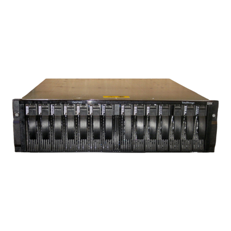
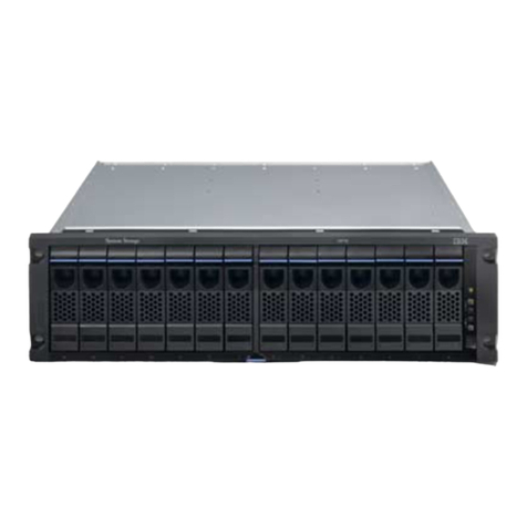
2. IBM TotalStorage DS4500 Fibre Channel Storage Server front bezel ............3
3. IBM TotalStorage DS4500 Fibre Channel Storage Server front view ............3
4. IBM TotalStorage DS4500 Fibre Channel Storage Server -back view ............4
5. Fibre Channel interface connections ........................4
6. LC-LC Fibre Channel cable ...........................6
7. Removing the fiber-optic cable protective caps ....................7
8. Inserting an LC-LC Fibre Channel cable into an SFP module ...............7
9. Inserting an LC-LC Fibre Channel cable into an installed SFP module............8
10. LC-LC Fibre Channel Cable lever and latches ....................9
11. Removing the LC-LC Fibre Channel cable ......................9
12. LC-SC Fibre Channel cable ...........................10
13. Removing the LC-SC cable adapter protective caps ..................11
14. LC-LC cable connected into the LC-SC cable adapter .................11
15. LC-LS Fibre Channel cable lever and latches ....................12
16. Removing the LC-LC Fibre Channel cable from an LC-SC Fibre Channel cable adapter.....12
17. DS4500 Storage Server interface ports.......................13
18. Host-side mini-hub interface ports ........................13
19. Drive-side mini-hub interface ports ........................14
20. Ethernet interface ports ............................18
21. Removing the DS4500 Storage Server bezel ....................21
22. Replacing the DS4500 Storage Server bezel ....................22
23. Connecting the power cords and power switch locations ................23
24. Storage server indicator lights ..........................27
25. RAID controller indicator lights ..........................29
26. Battery indicator lights .............................30
27. Fan and communications module indicator light ...................31
28. Power supply indicator light ...........................32
29. Mini-hub indicator lights ............................32
30. Fan and communications and power supply fault indicators ...............37
31. Storage server fan indicator ...........................37
32. Checking the battery service date.........................39
33. Controller status indicator lights .........................44
34. Removing and replacing afailed controller CRU ...................45
35. Indicator lights on the DS4500 Storage Server bezel..................46
36. Removing and installing abattery.........................48
37. Recording the battery support information......................49
38. Battery CRU indicator lights ...........................50
39. DS4500 Storage Server airflow .........................51
40. Removing and installing the storage server fan....................52
41. Storage server indicator lights ..........................53
42. Fan and communications module ports and indicator light ................55
43. Removing and installing afan and communications module ...............55
44. Power supply switch, ac power connectors, and indicator lights..............57
45. Removing and installing apower supply CRU ....................59
46. Replacing afailed SFP module .........................61
47. Unlocking the SFP module latch -plastic variety ...................61
48. Unlocking the SFP module latch -wire variety ....................62
49. Small Form-Factor Pluggable (SFP) Module .....................62
50. Installing an SFP module in amini hub.......................63
51. Removing the fiber-optic cable from the SFP module .................64
52. Removing and installing amini hub ........................65
©Copyright IBM Corp. 2005 vii
