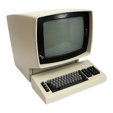
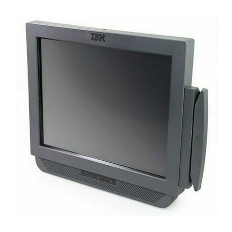
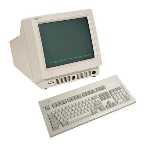
IBM 3180 1 User manual

f
S-
-;
4 ' 4
•
GU21-3207-1
File
NO.3180-1/S360/S370-06
:
E3
Model
1
Display
Station
User's
Guide
K , .
V. ^
Hi*
♦
o
r.

GU21-3207-1
File No.
3180-1/S360/S370-06
Model
1
Display
Station
User's
Guide

Second Edition (January1985)
This
major
revision
makes
obsolete
GU21
-3207-0.
Changes
or
additions
tothe
text
and
lllustrtins
are
indicated
bya
vertical
line
tothe
left
ofthe
changes
or
additions.
Changes
are
periodically
made
tothe
information
herein;
and
such
changes
will
be
reported in
subsequent
revisions or Technical Nesletters.
This
publication
is.for
planning
purposes
only.
The
information
herein
is
subject
to
changes before the products described becomeavailable.
References
in
this
publication
to
IBM
products,
programs,
or
services
do
not
imply
that
IBM
intends
to
rfiake
these
available
in
all
countries
in
which
IBM
operates.
Any
reference
to
an-JBM
licensed
program
in
this
publicatin
is
not
intended
to
state
or
imply
that
only
IBM's
licensed
program
may
used.
Any
functionally
equivalent
program
may
beused
instead.
. /
Requests
foc.lBM
publicatins
should
be
made
to
your
IBM
representative
ortothe
IBM
.
branch
office;Serving
your
locality.
(7'
This
publication
could
contain
technical
inaccuracies
or
typograghical
errors.
IBM
may
useor
distribute
whatever
information
you
supply
in
any
way
it
believes
appropriate
without
incurring
any
obligation
toyou.
©Copyright
International
Business
Machines
Corporation
1984,1985

Display
Station
Problems
Display
Station
Setup
Display
Station
Operation
Messages
and
Error
Codes
How
to
Obtain
IBM
Service
Appendixes
A
and
B

ABOUT
THIS MANUAL V
Purpose
of This Manual v
Organisation ofThis Manual v
Summary ofChanges vi
IfYou
Need
More
Information vi
CHAPTER
1.3180
SETUP
PROCEDURE
1
Section 1. WhatShould Be Done Prior to
Setup
1
Section 2. Setting Upthe DisplayStation 5
Section 3. Enteringthe DisplayStation ModelIDand the Keyboard
ID
14
Section 4. Connecting The DisplayStation 19
CHAPTER
2.
LEARNING
TO
OPERATE
THE
DISPLAY
STATION
23
Cleaning 23
Adjusting
TheSlopeofthe
Keyboard
24
Adjusting the Display 25
Operator Information Area 26
Keyboards 27
Power
Switch
29
Security
Keylock
29
DisplayStation Adjustments 30
AdjustingBrightness 30
Adjusting
Contrast 30
Adjusting
Alarm
Volume 30
AdjustingKeyboardClickerVolume 30
Turningthe KeyboardClickerOn or Off 31
Turningthe Cursor
Blink
On or Off 31
SelectingCursorStyle 31
Selecting Nomialor Reverse Image 31
Selecting DualCase/Mono Case (A,a) 31
Selecting Extended Display 31
Selecting Display
Dim
31
Special
Display
StationAdjustments 31
Selecting KeyboardID 32
Selecting ModelID 32
Selecting KeyboardNumericLock 32
Typewriter-Like
Keyboard
34typewriter/APL
Keyboard
34
Alt
Shift
35
Shift
35
Lock
35
Alphabet, Symbol,and Punctuation Mark 35
Dup 35
Field
Mark
35
PA1
and
PA2
35
Spacebar
37
Cursor
Control
37
New
Line
37
Tab
37
Back
Tab
37
Home
37
Horizontal Positioning 37
DoubleSpeed
Horizontal
Positioning
38
Vertical Positioning
38
Backspace
38
Fwd
and
Back
38
Numeric
Pad
39
Attn
39
Sys Rq 39
Clear 39
CursrSel
^
Er Inp 41
Erase
EOF
41
Print 41
Ident 41
Play
41
Test
41
Setup 41
Recrd 41
Reset
42
DvCnl
42
Insert 42
Delete 42
Enter
43
PF1 - PF24 43
Record 43
Play
^
CHAPTER
3.
OPERATOR
MESSAGES
AND
ERROR
CODES
45
OperatorMessages 45
Readiness andSystem
Connection
Symbols
46
Do
Not
Enter
(Input-Inhibited)
Messages
47
Reminders
X.21
Switched
Network
52
Shifts
and
Modes
53
DeviceDependent 53
Character
Highlighting
54
Printer Status 54
Cursor
Location
54
Four-Digit
ErrorCodes 55
CHAPTER 4. FIXINGDISPLAYSTATION PROBLEMS 59
Customer
Problem
Analysis
and
Resolution
(CPAR)
59
CPAR
Assistance
59
How To
Use
This
Chapter
59
ReferenceFigures 61
CPAR Procedures 62
CHAPTER
5. ELEMENT REMOVAL AND REPLACEMENT
PROCEDURES
97
How to
Obtain
IBM
Service
97
ElementExchangeand Replacement 98
Display
Element
Removal
and
Replacement
99
Keyboard
Element
Removal
and
Replacement
105
LogicElementRemovaland Replacement 107
Cable Attachment Module Removal and Replacement 111
Packing
Instructions
113
Display Element 113
Logic
Element
114
KeyboardElement 114
Cable
Attachment Module or PowerCord
115
APPENDIX A. BLANK TEMPLATE FOR CUSTOMER
MODIFIABLE KEYBOARD
117
INDEX
"9
Contents
iii
Purpose
of
This
Manual
About
This
Manual
This
manual
is
for
operators
and
supervisory
personnel
of
the
IBM
3180
Display
Station.
This
manual
can
be
used
as
alearning tool
as
well
as
a
source
of
reference
information.
It
describes
how
to:
Set
up
the
display
station
Enter,
modify,
and
remove
information
Use
and
understand
the
function
of
each
key
Respond
to
messages
and
error
codes
Perform
common
operator
tasks
Respond
to
problems
Exchange
elements
Pack
elements
that
need
replacing
Obtain
service
from
IBM
Organisation
of
This
Manual
This
manual
is
divided
into
chapters
and
appendixes:
Chapter
1explains
how
to
set
up
and
check
out
the
3180
Display Station. (This
does
not
include
setup
instructions
for
any
features.)
Chapter
2
explains
how
to
operate
the
display
station,
use
the
various keys,
make
display
and
keyboard
adjustments,
and
use
the
record
and
play functions.
Chapter
3lists
the
operator
messages
and
error
codes,
their
explanations,
and
recovery
procedures.
Chapter
4
explains
how
to
determine
which
hardware
element
is failing
through
protslem
analysis.
Chapter
5
explains
how
to
exchange,
remove
and
replace
failing
elements
and
how
to
obtain
service
from
IBM.
Appendix A
contains
a
sample
IBM
Service/Replacement
Order Form.
Appendix
B
explains
how
to
Modify
Keyboard
Keytops.
About
This
Manual

Summary
of
Changes
New information
has
been
added
to this manual to
support
the
typewriter/APL
keyboard.
If
You
Need
More
Information
You
may
wish
to
refer
to
one
of
the
following
publications:
•
IBM
3180
Display
Station
Keyboard
Template
Assignment
Sheet
and
Display
Screen
Layout
Sheet,
GX21-9467,
provides
row
and
column
layout
of
the
display
screen.
The
sheet
can
be
used
by a
programmer
to
develop
screens
and
can
also
be
filled
out
for
the
operator
as
a run
sheet.
• IBM
3180
Model
1
Display
Station
Introduction
and
Preinstallation
Planning
Manual.
GA21-9465.
VI

CHAPTER
1.
3180
SETUP
PROCEDURE
1
Section
1.
What
Should
Be
Done
Prior
to
Setup
1
Section 2. Setting Up
the
Display Station 5
Section
3. Entering
the
Display
Station
Model
ID
and
the
Keyboard ID 14
Section 4. Connecting
the
Display Station 19
Chapter
1.
3180
Setup
Procedure

Chapter
1.
3180
Setup
Procedure
SECTION
1.
WHAT
SHOULD
BE
DONE
PRIOR
TO
SETUP
Before
you
begin
to
set
up
the
3180,
make
sure
that:
• The physical and electrical preparation for your 3180 complies with the
requirements
in
the
IBM
3180
Mode!
11ntroduction
and
Preinstaflation
Planning
Manual,
GA21
-9465.
SAFETY
PRECAUTION
The
power
cord
and
plug
(when
supplied)
on
your
display
station
have
been
approved
for
use
with
this
display
station
and
meets
the
existing
testing
laboratory/test
house
standards.
For
your
safety,the
power
cord
and
plug
must
be
connected
to a
properly
wired
and
earthed
outlet.
An
improperlywired
outlet
or
plug
can
place
hazardous
voltages
on
accessible
metal
parts
of
this
display
station.
The
customer
is
responsible
for
the
outlet
wiring.
Ifit
becomes
necessary
to
change
the
power
cord
or
plug
or
if
the
outlet
is
improperly
wired,
have
the
change
made
according
to
local
or
national
code.
A
new
power
cord
may
be
ordered
from
your
IBM
sales
representative.
• The system or controlunityou are connectingyour3180 to is set up and
operating.
-
The
term
system
refers
to
the
controlling
or
highest
level
system
in a
configuration.
-
The
term
control
unit
refers
to
acontrolling
device
that
coordinates
work
station
operation
with
system
operation.
• Youhave a floor plan identifying the location and work station
ID
of your
3180.
If
the
preceding
items
have
been
completed,
continue
with
this
setup
procedure.
If
you
are
not
sure
or
cannot
check
off
all
the
preceding
items,
ask
the
person
who
planned
the
setup.
Chapter
1.
3180
Setup
Procedure
1

SAFETY
PRECAUTION
The display
element
should be moved
to
Its highest position before it is
moved from
one
location
to
another
(refer
to
step
2.2):
After yourdisplaystation has been unpacked, make sure you have ailof the
following:
•
Display
Element
Security
Keys
Logic
Element
HI'
ri
Keyboard
Element
Keyboard
Template

Cable
Attachment
Module
A
Power
Cord
Repair Identification
Tags
(located on
the
back
of
the
display
element)
Chapter
1.
3180
Setup
Procedure
3

Notes:
1.
Save
all
packaging
material
for
use
if
service
is
required.
2. Check
that
the
security keys
are
in
the
envelope
taped
to
the
top
of
the
top
of
the
display
element.
3.
Record
the
key identification
number
in
case
the
keys
are
lost
and
replacement
is
needed.
4. If you
use
special
keyboard
keytops,
use
Appendix
B
for
the
installation
instructions
and
the
form for recording
the
location of special keys.

SECTION
2.
SETTING
UP
THE
DISPLAY
STATION
2.1
Remove
the
repair
identification
(RID)
tags
from
the
back
of
the
display
element.
Place
them
on
the
logic
element
and
on
the
keyboard
element
in
the
positions
shown
below.
Note:
Service
cannot
be
obtained unless
these
tags
have been
installed.
Once
they
have
been
installed,
do
not
attempt
to
remove
them.
ir
13
C9468007
Chapter
1.
3180
Setup
Procedure
5

2.2
Adjust
the
display
element:
• Pushinthe side knobsand
pull
the display element up
until
it
stops.
Tilt
the
display
element
forward.
• Remove
the
tape
from
the
back of
the
display element.
C9468008

Place
the
keyboard
in
front
of
the
display
element
and
position
the
keyboard
template
on
the
keyboard.
Remove
the
plastic
covering
from
the
keyboard
cable
by
pulling
straight
out.
(Some
cables
may
not
have
a
plastic
covering.)
Chapter
1.
3180
Setup
Procedure
7

IB
Make
sure
the
lever
on
the
bottom
of
the
logic
element
is
turned
to
the
open
position.
I'M
>>
ill..
..I
!.l
Closed
CAUTION
When
performing
the
following
step,
do
not
touch
anything
on
the
inside
of
the
logic
element
except
the
tape.
Remove
the
aluminum
foil
from
the
logic
element;
then
remove
the
tape
from
the
connector.
Aluminum
Taoe
©J
Foil
Fconnectoo

Make
sure
the
two
locking
bars
on
the
right
latches
of
the
logic
element
are
pushed
as
shown
below.
Ho
disDla
Locking-
Bars
Latches
Chapter
1.
3180
Setup
Procedure

Firmly
display
are
sei
to
the
Slide
the
locking
bars
on
the
right
latches
as
shown
below.
Locking Bars

Turn
the
lever
on
the
bottom
of
the
logic
element
to
the
closed
position.
Closed
Chapter
1.
3180
Setup
Procedure
11

i
An
alarm
will
sound,
pause
briefly,
sound
again,
andstop;
then the following display
will
appear:
^EEEBEEEEEEEEEEEEEEEEEEEEEEEEEEEEEEEEJEEEEEEEEEEEEEEEEEEEBEEBEEEEEEEEEEEEEEEEI
h\
" H
NomMl Inlentity H't
/High
InMntitv
H's
I
R«varM
Imsg*
H's
H
'AAAAAAAAAAAAAAAAAAAAMAAAAAAAAAAAAAAAAS;
H
HHHHHKHHKyHHHHtWHHHHHHHHHHKHHHHKHHHHK
H
H ( H
H
HHHHHHHHHHHHNHfHHKHHHHHKHHHHHHHHHHHKH
H
/ H
H H / H
JEEEEEEEBEEEEEEEEEEBEEEEEEEEEEEEEEEEEBEJEEEEEEEEEEJBe^EEEEEEEEEEEEEEEEEEEEEEEEE*
Atinbuiet trom Lgftto Rioht
^•verM
IrrwQe
E
Normal
E
Blinking £
H-ph
Inienxlv
E
Bl*rvk
Pofibon
Undeftcor*
E
Ravara* lmag« E
Cursor
Row
Column
ImtYor mty not b«ditplaysdl
Do
all
the
above
conditions
occur?
Section 3, Entering
the
Display
Station
Model
ID
and
the
Keyboard
ID
Table of contents
Other IBM Touch Terminal manuals

IBM
IBM SurePOS 500 Use and care manual

IBM
IBM 4810 33H Installation and maintenance instructions

IBM
IBM 31x Installation and maintenance instructions

IBM
IBM Asynchronous Color Terminals WS525 User manual

IBM
IBM 4820 Technical manual

IBM
IBM 4695 User manual

IBM
IBM 4851 514 Technical manual

IBM
IBM NetVista Kiosk DBCS User manual

IBM
IBM XStation 130 Setup guide

IBM
IBM VGB26 User manual