3279
MIM
Preface
Part
2 comprises the Maintenance Analysis
Procedures.
ii
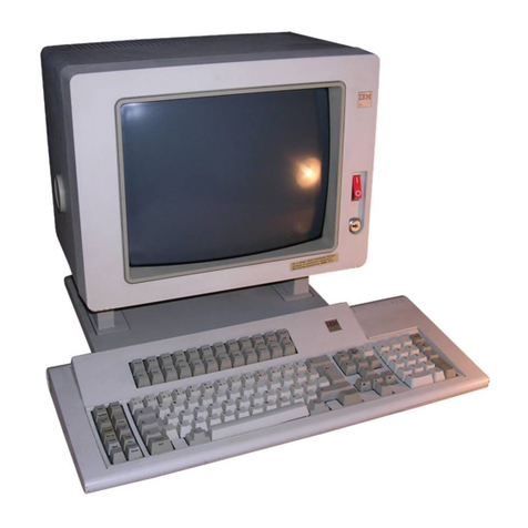
This publication contains the information needed
to
service
and
maintain the IBM
3279
Color Display
Station Models 2A, 2B, 3A,
and
3B.
Part 1 comprises the Maintenance Information
and
Parts Catalog.
If
this machine
is
fitted with
any
RPQ
features,
any
extra
RPQ
documentation
can
he
found
in
a
tray
under
the keyboard.
Fourth Edition, November 1981
This is a major revision of,
and
obsoletes, SY33-0069-2.
The
drawings
and
specifications contained herein shall
not
he reproduced
in
whole
or
in
part without written permission.
IBM has prepared this maintenance manual for the use of IBM customer
engineers in the installation. maintenance, or repair
of
the specific
machines indicated. IBM makes no representations
that
it is suitable for
any
other
purpose.
Information contained in this manual
is
subject
to
change from time
to
time.
Any
sllch change will be reported in subsequent revisions
or
Technical Newsletters.
It
is possible
that
this material may contain references to,
or
information
abollt, IBM products (machines or programs), programming,
or
services
that
are
not
announced in your country. Such references
or
information
must
not
be construed
to
mean
that
IBM intends
to
announce such IBM
products, programming,
or
services in your country.
Publications are not stocked
at
the addresses given below; requests for
IBM publications should be made
to
your IBM representative
or
to
the
IBM
branch
office serving your locality.
A form for reader's comments
is
provided
at
the back
of
this publication;
if the form has been removed, comments may be addressed
to
either:
• International Business Machines Corporation, Department
812H,
1133 Westchester Avenue, White Plains,
New
York 10604.
or
IBM United Kingdom Laboratories Limited,
Product
Publications, Mail
Point 95, Hursley Park, Winchester, Hampshire
S021
2JN, England.
IBM may use or distribute whatever information you supply
in
any
way
it
believes appropriate without incurring
any
obligation
to
you.
e Copyright International Business Machines Corporation 1979, 1980,
1981
