Figures
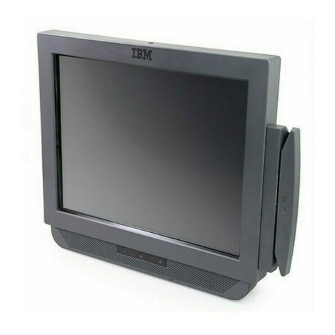
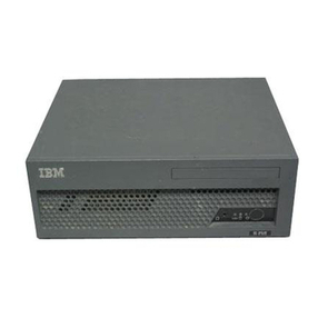
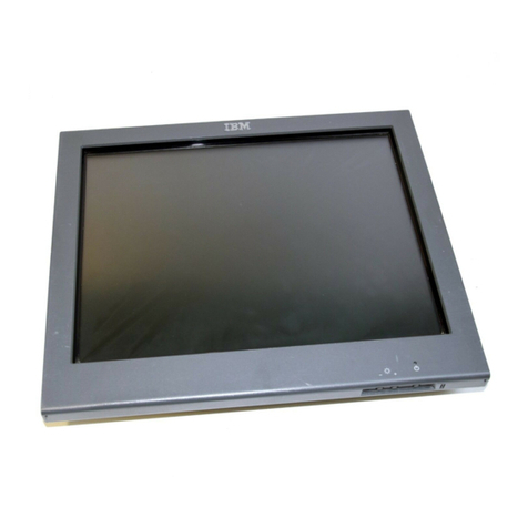
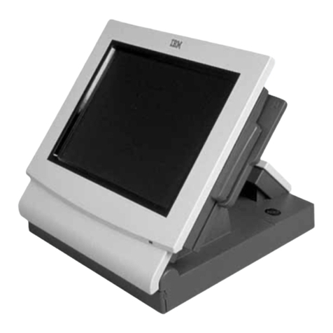
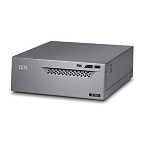
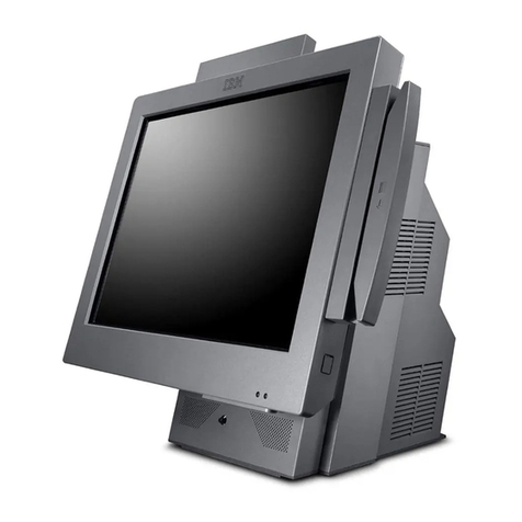
1. IBM SurePOS 500 Model 514 and supported devices..................1
2. Serial number location .............................4
3. IBM 4851 connectors..............................5
4. Memory module location ............................7
5. Memory module removal and insertion .......................8
6. Installing the magnetic stripe reader (MSR) .....................9
7. Routing the integrated display cables .......................10
8. Installing the integrated customer display ......................11
9. Assembling and installing the wireless adapter ....................11
10. Installing the antenna enclosure .........................12
11. Cable routing label ..............................13
12. Location of power switch and screen brightness adjusting buttons.............14
13. Base plate countertop dimensions ........................21
14. Attaching the base foot to the countertop ......................22
15. Countertop with non-keyboard-integration tray mounting ................23
16. Countertop integration tray pattern with display and countertop cutout on right side ......24
17. Detaching the fence from the tray.........................24
18. Sliding the fence off of the integration tray .....................25
19. Overview of integration tray, SurePOS 500 Model 514, printer, and filler panels ........26
20. Connecting filler panels ............................27
21. Attaching the integration tray to cash drawer ....................28
22. Attaching amounting plate to center of cash-drawer integration tray ............29
23. Attaching mounting plate to the cash drawer integration tray ...............30
24. Attaching filler panels and the rear modesty cover ..................32
25. Full-size keyboard-integration tray on acountertop ..................33
26. Countertop keyboard-integration tray assembly....................35
27. Installing the keyboard-integration tray on acash drawer ................36
28. Installing the SurePOS 500 Model 514 onto the integration tray .............37
29. Installing the 4610 printer onto the integration tray ..................38
30. Installing the keyboard onto the integration tray ...................39
31. Attaching the distributed customer display cable ...................39
32. Installing the distributed customer display onto the integration tray ............40
33. Attaching the distributed customer display cable ...................42
34. Attaching the distributed customer display to the system unit...............43
35. Installing the distributed customer display onto the keyboard integration tray .........44
36. 4610 TF6 or TF7 printer connector locations.....................45
37. Attaching and routing the cables to the printer. ....................46
38. Attaching the 4610 TF6 or TF7 printer mounting plate for anon-keyboard integration tray ....46
39. 4610 TF6 or TF7 cable routing..........................47
40. Display tablet, remove and replace ........................55
41. Removing the tablet back cover .........................56
42. Removing the control card ...........................57
43. Location of EMC shields and common screw ....................58
44. Removing the tablet touch card .........................59
45. Removing the LCD assembly ..........................60
46. Rear cover removal ..............................61
47. Unlatching rear cover .............................62
48. Removing the rear metal panel cover .......................63
49. Cable-tie bar remove and replace.........................64
50. Tailgate remove and replace ..........................65
51. Removing the system board...........................66
52. System board jumper location ..........................67
53. Battery location ...............................68
Updated October, 2008
©Copyright IBM Corp. 2005, 2008 vii
