manuals.online logo
Brands
  1. Home
  2. •
  3. Brands
  4. •
  5. IBM
  6. •
  7. Touch Terminal
  8. •
  9. IBM 4693 Operating instructions

IBM 4693 Operating instructions

Store Systems:
ÉÂÔ
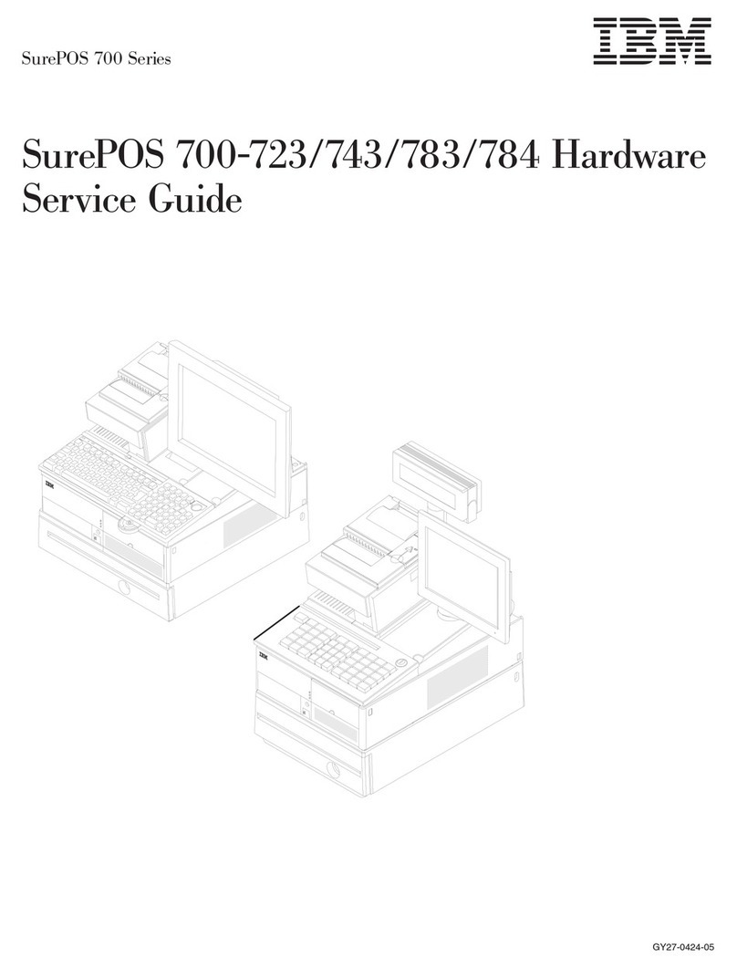
Installation and Operation Guide for
Point-of-Sale Input/Output Devices
Created February 23, 1997
GA27-4028-01
Store Systems:
ÉÂÔ
Installation and Operation Guide for
Point-of-Sale Input/Output Devices
Created February 23, 1997
GA27-4028-01
Created February 23, 1997
Note
Before using this information and the product it supports, be sure to read the general information under “Notices” on page v.
Translations of the safety notices are found in the
IBM 4693/4694 Point of Sale Terminals: Product Safety Information
, P/N
60G1330, that is shipped with the point-of-sale terminal if required.
Second Edition (November 1995)
This is the second edition of the
IBM* Store Systems: Installation and Operation Guide for Point-of-Sale Input/Output Devices
. This
edition replaces and obsoletes IBM Store Systems: Installation and Operation Guide for Point-of-Sale Input/Output Devices,
GA27-4028-00.
Order publications through your IBM representative or the IBM branch office serving your locality. Publications are not stocked at the
address given below.
Forms for readers’ comments appear at the back of this publication. If the forms have been removed, address your comments to:
IBM Corporation, Information Development, Department CJMA
PO Box 12195
Research Triangle Park, North Carolina 27709-9990
USA
When you send information to IBM, you grant IBM a nonexclusive right to use or distribute the information in any way it believes
appropriate without incurring any obligation to you.
 Copyright International Business Machines Corporation 1994, 1995. All rights reserved.
Note to U.S. Government Users — Documentation related to restricted rights — Use, duplication or disclosure is subject to
restrictions set forth in GSA ADP Schedule Contract with IBM Corp.
Created February 23, 1997
Contents
Notices . . . . . . . . . . . . . . . . . . . . . . . . . . . . . . . . . . . . . . . . . . . . . . . . . . . . . . . . v
Trademarks . . . . . . . . . . . . . . . . . . . . . . . . . . . . . . . . . . . . . . . . . . . . . . . . . . . v
General Safety Information ............................................ vi
Electronic Emission Notices .......................................... vii
Preface . . . . . . . . . . . . . . . . . . . . . . . . . . . . . . . . . . . . . . . . . . . . . . . . . . . . . . . viii
Related Publications . . . . . . . . . . . . . . . . . . . . . . . . . . . . . . . . . . . . . . . . . . . . . . viii
Related Diskettes . . . . . . . . . . . . . . . . . . . . . . . . . . . . . . . . . . . . . . . . . . . . . . . . viii
Summary of Changes .............................................. ix
Chapter 1. Installing Input/Output Devices ................................ 1-1
Installing I/O Devices .............................................. 1-3
Installing the Cash Drawer and the System Unit ............................. 1-5
Installing the Compact Cash Drawer Coin Roll Cutter .......................... 1-6
Using the Compact Cash Drawer Coin Roll Cutter ............................ 1-6
Installing the 9-Inch Video Display ..................................... 1-7
Installing an Integrated Keyboard ...................................... 1-7
Installing the Fillers .............................................. 1-8
Installing the Printer .............................................. 1-9
Securing I/O Devices to the System Unit ................................ 1-10
Installing the Alphanumeric Display .................................... 1-10
Installing the 40-Character Liquid Crystal Display ........................... 1-11
Install 40-Character Vacuum Fluorescent Display II .......................... 1-12
Installing the Character Graphics Display ................................ 1-12
Installing the Shopper Display ....................................... 1-13
Installing a Flat Panel or Sure Point Touch Display .......................... 1-14
Installing the Distribution Kit ........................................ 1-15
Installing the Integration Kit ........................................ 1-15
Installing the Optional MSR Kit on the Sure Point Touch Display .................. 1-16
Installing the Signature Capture Device ................................... 1-17
Installing the RS232 Interface Model ................................... 1-17
Installing the RS485 Interface Model ................................... 1-17
Installing and Removing Keylocks ...................................... 1-18
Preparing to Install a Lock or a Blank Lock Insert ........................... 1-18
Installing a Lock Insert ........................................... 1-19
Removing a Lock Insert .......................................... 1-20
Installing a Blank Lock Insert ....................................... 1-20
Removing a Blank Lock Insert ....................................... 1-20
Installing the System Unit Rear Cover .................................. 1-21
Chapter 2. Operating Point-of-Sale I/O Devices ............................. 2-1
Displays . . . . . . . . . . . . . . . . . . . . . . . . . . . . . . . . . . . . . . . . . . . . . . . . . . . . . . 2-2
Adjusting the Controls on Video Displays ................................. 2-3
Cash Drawers . . . . . . . . . . . . . . . . . . . . . . . . . . . . . . . . . . . . . . . . . . . . . . . . . . . 2-4
Keylock Positions . . . . . . . . . . . . . . . . . . . . . . . . . . . . . . . . . . . . . . . . . . . . . . . 2-5
Document Storage Area Under Cash Till ................................. 2-5
Keyboards . . . . . . . . . . . . . . . . . . . . . . . . . . . . . . . . . . . . . . . . . . . . . . . . . . . . . 2-5
Function Keys . . . . . . . . . . . . . . . . . . . . . . . . . . . . . . . . . . . . . . . . . . . . . . . . . 2-6
Manager’s Keylock . . . . . . . . . . . . . . . . . . . . . . . . . . . . . . . . . . . . . . . . . . . . . . 2-6
Keyboard Lights (Status Indicators) ..................................... 2-7
 Copyright IBM Corp. 1994, 1995 iii
Created February 23, 1997
Printers . . . . . . . . . . . . . . . . . . . . . . . . . . . . . . . . . . . . . . . . . . . . . . . . . . . . . . 2-7
Operating the Model 2 Point of Sale Printer ................................. 2-8
Opening/Closing the Document Insert Station ............................... 2-8
Inserting Documents in the Model 2 Printer ................................ 2-9
Advancing the Journal Paper on the Model 2 Printer .......................... 2-10
Advancing the Customer Receipt ..................................... 2-10
Tearing the Customer Receipt ....................................... 2-10
Unlocking the Journal Cover ........................................ 2-10
Testing the Model 2 Printer ........................................ 2-11
Operating the Model 3 or 4 Point of Sale Printer .............................. 2-11
Inserting Documents in the Model 3 or 4 Printer ............................ 2-11
Aligning the Print Line on an Inserted Document ............................ 2-13
Advancing the Customer Receipt Paper or Journal Paper ....................... 2-13
Unlocking the Journal Cover ........................................ 2-13
Testing the Model 3 or 4 Printer ..................................... 2-14
Model 4A Point of Sale Printer ........................................ 2-15
Model 3R and Model 4R Point of Sale Printers .............................. 2-15
Operating the Model 3R and Model 4R Printer ............................. 2-16
Entering Data at Your Terminal ........................................ 2-18
Operating Card Readers and Bar Code Readers ............................ 2-18
Cleaning the Card Reader ......................................... 2-19
Entering Data with the Hand-Held Bar Code Readers ......................... 2-19
Operating the Signature Capture Device .................................. 2-20
Signature Submission . . . . . . . . . . . . . . . . . . . . . . . . . . . . . . . . . . . . . . . . . . . . 2-20
Replacing the Pen Refill – Version 1 ................................... 2-20
Replacing the Pen Refill – Version 2 ................................... 2-20
Appendix A. Expendable Supplies and Replaceable Parts ...................... A-1
How to Order Expendable Supplies ...................................... A-1
Ribbon Cartridge for Point-of-Sale Printers ................................ A-1
Roll Paper for Point-of-Sale Printers .................................... A-2
Additional Forms for Point-of-Sale Printer Model 2 ............................ A-3
Additional Forms for Point-of-Sale Printer Model 3 or 4 ......................... A-4
Appendix B. Operator and Programmer Information .......................... B-1
Operator Techniques for the Point-of-Sale Printers ............................. B-1
Application Program Techniques for Point-of-Sale Printers ......................... B-1
Appendix C. Display Configurations and Controls ........................... C-1
Flat Panel Display Controls ........................................... C-1
Flat Panel Display Sleep Control ...................................... C-2
Sure Point Touch Display Controls ....................................... C-3
Sure Point Touch Display Beeper Controls ................................ C-3
Touch Display Sleep Control ........................................ C-4
Sure Point Touch Display Calibration .................................... C-5
Index . . . . . . . . . . . . . . . . . . . . . . . . . . . . . . . . . . . . . . . . . . . . . . . . . . . . . . . . X-1
iv Installation and Operation for POS I/O Devices
Created February 23, 1997
Notices
The following paragraph does not apply to the United Kingdom or any country where such provisions are
inconsistent with local law: INTERNATIONAL BUSINESS MACHINES CORPORATION PROVIDES THIS
PUBLICATION "AS IS" WITHOUT WARRANTY OF ANY KIND, EITHER EXPRESS OR IMPLIED,
INCLUDING, BUT NOT LIMITED TO THE IMPLIED WARRANTIES OF MERCHANTABILITY OR
FITNESS FOR A PARTICULAR PURPOSE. Some states do not allow disclaimer of express or implied
warranties in certain transactions, therefore, this statement may not apply to you.
References in this publication to IBM products, programs, or services do not imply that IBM intends to
make these available in all countries in which IBM operates. Any reference to an IBM product, program,
or service is not intended to state or imply that only IBM’s product, program, or service may be used. Any
functionally equivalent product, program, or service that does not infringe any of IBM’s intellectual property
rights maybe used instead of the IBM program, product, or service. Evaluation and verification of
operation in conjunction with other products, except those expressly designated by IBM, are the user’s
responsibility.
IBM may have patents or pending patent applications covering subject matter in this document. The
furnishing of this document does not give you any license to these patents. You can send license
inquiries, in writing, to the IBM Director of Licensing, IBM Corporation, 500 Columbus Avenue, Thornwood,
NY 10594 USA.
Trademarks
The following terms, denoted by an asterisk (*) in this publication, are trademarks of the IBM Corporation
in the United States or other countries or both:
The following terms, denoted by a double asterisk (**) in this publication, are trademarks of other
companies:
IBM PS/2 Sure Point Touch Screen
Checkmate Checkmate Electronics Inc.
Cross A.T.X International Inc.
Contents v
Created February 23, 1997
General Safety Information
The following general safety considerations should be observed whenever you work with electricity or with
any electronic equipment.
DANGER
Never work on equipment or connect or disconnect signal cables during periods of
lightning activity.
CAUTION:
For your safety, connect equipment requiring electrical power to a properly wired and grounded
outlet.
The following general safety considerations should be observed whenever you work with a point-of-sale
printer.
CAUTION:
For safety when running the printer test, make sure personal articles such as ties, necklaces, or
bracelets do not get caught in the moving print head.
The following general consideration should be observed whenever you replace batteries in a point-of-sale
terminal.
Return used Ni Cd (storage retention) batteries to IBM.
Replaceable Lithium Battery inside system unit.
Non-replaceable Lithium Battery inside adapter.
vi Installation and Operation for POS I/O Devices
Created February 23, 1997
Electronic Emission Notices
Federal Communications Commission (FCC) Statement
Note: This equipment has been tested and found to comply with the limits for a Class A digital device,
pursuant to Part 15 of the FCC Rules. These limits are designed to provide reasonable protection against
harmful interference when the equipment is operated in a commercial environment. This equipment
generates, uses, and can radiate radio frequency energy and, if not installed and used in accordance with
the instruction manual, may cause harmful interference to radio communications. Operation of this
equipment in a residential area is likely to cause harmful interference, in which case the user will be
required to correct the interference at his own expense.
Properly shielded and grounded cables and connectors must be used in order to meet FCC emission
limits. IBM is not responsible for any radio or television interference caused by using other than
recommended cables and connectors or by unauthorized changes or modifications to this equipment.
Unauthorized changes or modifications could void the user's authority to operate the equipment.
This device complies with Part 15 of the FCC Rules. Operation is subject to the following two conditions:
(1) this device may not cause harmful interference, and (2) this device must accept any interference
received, including interference that may cause undesired operation.
Canadian Department of Communications compliance statement
This equipment does not exceed Class A limits per radio noise emissions for digital apparatus, set out in
the Radio Interference Regulation of the Canadian Department of Communications. Operation in a
residential area may cause unacceptable interference to radio and TV reception requiring the owner or
operator to take whatever steps are necessary to correct the interference.
Avis de conformité aux normes du ministère des Communications du Canada
Cet équipement ne dépasse pas les limites de Classe A d'émission de bruits radioélectriques pour les
appareils numériques, telles que prescrites par le Règlement sur le brouillage radioélectrique établi par le
ministère des Communications du Canada. L'exploitation faite en milieu résidentiel peut entraîner le
brouillage des réceptions radio et télé, ce qui obligerait le propriétaire ou l'opérateur à prendre les
dispositions nécessaires pour en éliminer les causes.
United Kingdom Statement of Compliance
The United Kingdom Telecommunications Act 1984. This apparatus is approved under approval number
NS/G/1234/J/100003
for indirect connections to the public telecommunications systems in the United Kingdom.
Laser Product Identification
Some IBM Scanners are laser products. Where required, the scanner has a label that identifies its
classification. For example, information on the label in the U.S.A. is shown below.
Class IIa Laser Product -
Avoid Long-Term
Viewing of Direct Light
Contents vii
Created February 23, 1997
Preface
This guide describes how to install and operate the Input/Output (I/O) devices on IBM point-of-sale
terminals. It also describes how to exchange expendable supply items, such as ribbons and paper. It
contains two chapters and three appendies.
It is written primarily for users who prepare training material and store procedures. Retain the guide for
future use when installing additional terminals or point-of-sale devices.
Chapter 1 Describes the procedures for installing I/O devices
Chapter 2 Provides illustrations of terminals and I/O devices and includes descriptions on how to use
the devices. on IBM point-of-sale terminals.
Appendix A Contains information for ordering customer replaceable parts and expendable supplies.
Appendix B Contains information for operators and programmers.
Appendix C Contains information on display configurations and controls.
Related Publications
Related Diskettes
Related Publication Name Form No.
IBM 4693 Point of Sale Terminals: Installation and Operation Guide
SA27-3978
IBM 4694 Point of Sale Terminals: Installation and Operation Guide
SA27-4005
IBM Store Systems: Hardware Service Manual for Point-of-Sale Input/Output Devices
SY27-0339
IBM 4693, 4694, and 4695 Point of Sale Terminals: Hardware Service Manual
SY27-0337
IBM 4693, 4694, and 4695 Point of Sale Terminals: Maintenance and Test Summary
SX27-3919
IBM 4695 Point of Sale Terminals: Installation and Operation Guide
GA27-4031
IBM Store Systems: Parts Catalog
S131-0097
IBM Store Systems: Supplement for Point of Sale Terminals – Installation, Operation,
and Service
GA27-4035
Related Diskettes Form No.
IBM 4693 Point of Sale Terminals: Reference Diskette
SX27-3918
IBM 4693 Point of Sale Terminals: Diagnostic Diskette
SX27-3928
IBM 4693 Point of Sale Terminals: Support Diskette for Medialess Terminals
SX27-3929
IBM 4694 Point of Sale Terminals Service Diskette
SX27-3933
IBM 4693/4694 Point of Sale Terminals Supplemental Drivers
SX27-3934
IBM 4695 Point of Sale Terminals Service Diskette
SX27-3965
IBM Point-of-Sale Subsystem for DOS
(1 of 2) SX27-3960
SX27-3961
IBM Point-of-Sale Subsystem for OS/2
(1 of 2) SX27-3942
SX27-3943
viii Installation and Operation for POS I/O Devices
Created February 23, 1997
Summary of Changes
GA27-4028-01 (November 1995)
This edition includes installation and operation information about the following point-of-sale input/output
devices:
¹9–inch Video Display
¹Sure Point Monochrome Touch Screen
¹Sure Point Color Touch Screen
¹Compact Cash Drawer
¹Keyboard Filler Panel
¹Special characters for the MICR Printer.
 Copyright IBM Corp. 1994, 1995 ix
Created February 23, 1997
xInstallation and Operation for POS I/O Devices
Created February 23, 1997
Chapter 1. Installing Input/Output Devices
Installing I/O Devices .............................................. 1-3
Installing the Cash Drawer and the System Unit ............................. 1-5
Installing the Compact Cash Drawer Coin Roll Cutter .......................... 1-6
Using the Compact Cash Drawer Coin Roll Cutter ............................ 1-6
Installing the 9-Inch Video Display ..................................... 1-7
Installing an Integrated Keyboard ...................................... 1-7
Installing the Fillers .............................................. 1-8
Installing the Keyboard Filler Panel ................................... 1-9
Installing the Printer .............................................. 1-9
Securing I/O Devices to the System Unit ................................ 1-10
Installing the Alphanumeric Display .................................... 1-10
Installing the 40-Character Liquid Crystal Display ........................... 1-11
Install 40-Character Vacuum Fluorescent Display II .......................... 1-12
Installing the Character Graphics Display ................................ 1-12
Installing the Shopper Display ....................................... 1-13
Installing a Flat Panel or Sure Point Touch Display .......................... 1-14
Installing the Distribution Kit ........................................ 1-15
Installing the Integration Kit ........................................ 1-15
Installing the Optional MSR Kit on the Sure Point Touch Display .................. 1-16
Installing the Signature Capture Device ................................... 1-17
Installing the RS232 Interface Model ................................... 1-17
Installing the RS485 Interface Model ................................... 1-17
Installing and Removing Keylocks ...................................... 1-18
Preparing to Install a Lock or a Blank Lock Insert ........................... 1-18
Installing a Lock Insert ........................................... 1-19
Removing a Lock Insert .......................................... 1-20
Installing a Blank Lock Insert ....................................... 1-20
Removing a Blank Lock Insert ....................................... 1-20
Installing the System Unit Rear Cover .................................. 1-21
 Copyright IBM Corp. 1994, 1995 1-1
Created February 23, 1997
Before You Start
These setup instructions describe how to install devices and connect cables on IBM 4693, 4694, and
4695 Point of Sale Terminals.
Your Store Planner should provide some instructions that show the devices your terminal has and
where you should connect them. If that arrangement is different than the one shown here, follow the
Planner’s instructions.
The printer, short keyboard, displays, and fillers can be placed on the left or on the right.
Video displays should be placed on the left side of the Model 3R and 4R printers.
To install the terminal:
1Get the cables from the OPEN FIRST box as needed.
2Follow the directions of your Store Planner in arranging the devices.
Figure 1-1. Point-of-Sale Terminal with I/O Devices
1-2 Installation and Operation for POS I/O Devices
Created February 23, 1997
Installing I/O Devices
Note: This section provides information to set up I/O devices most often found on point-of-sale terminals.
The figure below shows typical socket panels at the rear of the system unit. The panels differ slightly,
depending on the model of your terminal. Refer to Table 1-1 on page 1-4 when plugging your cables.
ACin
38V
SerialBSerialA
VideoACPowerOutlet
Parallel Video Auxiliary
34
12
7
Keyboard
3A 3B 4A 4B 9A 9B 11
5A 5B 9C
Typical 4693
4694 Model 041, 044 or 144
4694 Model 001, 004 or 024
Power
Connector
PCMCIASlots
AB
1234
Power
Connector
PCMCIASLOTS
AB
1234
Chapter 1. Installing Input/Output Devices 1-3
Created February 23, 1997
Table 1-1. Plug Locations for I/O Devices
Type of Device Box No. Cable No. System Unit
Socket Notes
Cash Drawer 3 3 3A or 3B 1
40-Character Vacuum Fluorescent Display
40-Character VFD II,
40-Character Liquid Crystal Display,
Character/Graphics Display,
Shopper Display
4 4 4, 4A, 4B, 9A, 9B 1
Flat Panel Display LCD 4 and LCD 4 and 2
Video Display
Keyboard 5 5 5, 5A, 5B, or 1
Printer 7 7 7
Scanner or Hand-held Bar Code Reader 9, 9C, or 9/E 1
4693 Model 202 (satellite terminal) 11 11
RS232C Device or 1
Parallel Printer , option adapter
slots 1 or 2
Mouse
Option Adapters 2
Notes: :
1. Plug the cables according to your Store Planner’s instructions.
2. Your terminal may have one or more option adapters installed at the time of manufacture. Follow your Store
Planner’s instructions for connecting any cables to these adapters.
1-4 Installation and Operation for POS I/O Devices
Created February 23, 1997
Installing the Cash Drawer and the System Unit
1Place the cash drawer in the desired
location.
2Place the system unit on top of the cash
drawer, if the unit is integrated.
3Open the rear cover on the cash drawer and
remove it.
4Connect the cash drawer cable to the 3A or
3B socket on the rear panel of the system
unit.
5Connect the other end of the cable to the
rear of the cash draw (socket 3).
6Connect the AC power cord to the system
unit.
Do not plug the other end of power cord
to an outlet yet.
7Route the power cord down toward the
bottom of the cash drawer.
8Install the cash drawer rear cover.
Note: Other models may vary.
9The cash drawer is installed. Install any
other I/O devices at this time, otherwise go
to “Installing the System Unit Rear Cover” on
page 1-21.
Cover
Release
Button
(Both Sides)
Pin Power Cord
Rear Cover
Hole
3
Chapter 1. Installing Input/Output Devices 1-5
Created February 23, 1997
Installing the Compact Cash
Drawer Coin Roll Cutter
1Open the cash drawer and pull it all the way
out.
2Remove the till.
3From inside the drawer, squeeze the cutter
latches together with your fingers and push
the cutter outward until it can be removed
from the outside.
4To exchange the cutter, snap the new one
into position from the outside.
5Reassemble.
Using the Compact Cash Drawer
Coin Roll Cutter
1. Either push or pull the roll against the coin roll
cutter until a score is made in the outside
cover.
2. Then break roll open with your hands.
Coin Roll Opener
1-6 Installation and Operation for POS I/O Devices
Created February 23, 1997
Installing the 9-Inch Video
Display
1Hold the display and its base over the
system unit and route the two cables through
the opening at the rear of the base.
2Ensure that two tabs at bottom rear of the
display base fit into slots in top of system
unit.
3Place the display base over the three screw
holes in top of the system unit and tighten
the screws.
Note: The display should be mounted on
the left side when used with the Model 3R or
4R printer.
4The display is installed. Install any other I/O
devices at this time, otherwise go to
“Installing the System Unit Rear Cover” on
page 1-21.
Installing an Integrated Keyboard
Note: If your keyboard cable has a round plug
on one end, it may be easier to first connect the
round plug to the system unit and then route the
cable up through the opening of the system unit
that is inline with the keyboard socket. If the plug
is not round, follow these instructions.
1Connect cable 5 to the keyboard.
2Route the keyboard cable straight back and
through the nearest opening at the rear of
the system unit.
3Place the keyboard so the slots in the front
of keyboard engage with tabs at the front
edge of system unit.
4Be sure the side of the keyboard overlaps
the tabs on the side of the system unit.
5Be sure the carder reader opening is aligned
with the slot in the system unit.
6The keyboard is installed. Install any other
I/O devices at this time, otherwise go to
“Installing the System Unit Rear Cover” on
page 1-21.
Slot
Tab
Tabs
Slots
Card
Reader
Openings
Chapter 1. Installing Input/Output Devices 1-7
Created February 23, 1997
Installing the Fillers
Notes:
1. On an integrated unit, pull out on the locking
lever at the left side of system unit.
2. Ensure that the side of each filler overlaps the
tab on the side of the system unit.
1If you have a video display on an integrated
terminal:
aMove the display on its arm to the side
and remove any tape holding the
alignment ring.
bRemove knockout section of display
filler.
cAlign the display filler with the
alignment ring and slide the filler onto
the ring. Press the display filler into
place.
2If you do not have a video display:
aPlace the display filler on the system
unit. DO NOT REMOVE the knockout
section.
3If you have a short keyboard:
aPlace the keyboard filler beside the
keyboard. The fillers are installed.
Install any other I/O devices at this
time, otherwise go to “Installing the
System Unit Rear Cover” on
page 1-21.
Display
Filler
Alignment
Ring
DisplayFiller
Keyboard
Filler
Knockout
Section
1-8 Installation and Operation for POS I/O Devices

This manual suits for next models

2

Other IBM Touch Terminal manuals

IBM 3270 Manual

IBM

IBM 3270 Manual

IBM 4851 514 Technical manual

IBM

IBM 4851 514 Technical manual

IBM 3151 User manual

IBM

IBM 3151 User manual

IBM XStation 130 Setup guide

IBM

IBM XStation 130 Setup guide

IBM 3180 1 User manual

IBM

IBM 3180 1 User manual

IBM 4613 SurePOS User manual

IBM

IBM 4613 SurePOS User manual

IBM 3270 User manual

IBM

IBM 3270 User manual

IBM 4695 User manual

IBM

IBM 4695 User manual

IBM 31x Installation and maintenance instructions

IBM

IBM 31x Installation and maintenance instructions

IBM VGB26 User manual

IBM

IBM VGB26 User manual

IBM SurePOS 700 Series User manual

IBM

IBM SurePOS 700 Series User manual

IBM SurePOS 500 Use and care manual

IBM

IBM SurePOS 500 Use and care manual

IBM Models 5 User manual

IBM

IBM Models 5 User manual

IBM NetVista Kiosk DBCS User manual

IBM

IBM NetVista Kiosk DBCS User manual

IBM 4810-E3H Installation and maintenance instructions

IBM

IBM 4810-E3H Installation and maintenance instructions

IBM 3279 2A Setup guide

IBM

IBM 3279 2A Setup guide

IBM Asynchronous Color Terminals WS525 User manual

IBM

IBM Asynchronous Color Terminals WS525 User manual

IBM 4910-33S User manual

IBM

IBM 4910-33S User manual

IBM 4820 Technical manual

IBM

IBM 4820 Technical manual

IBM 3774 Manual

IBM

IBM 3774 Manual

IBM 4810 33H Installation and maintenance instructions

IBM

IBM 4810 33H Installation and maintenance instructions

Popular Touch Terminal manuals by other brands

Rockwell Automation Allen-Bradley PanelView 5510 Series user manual

Rockwell Automation

Rockwell Automation Allen-Bradley PanelView 5510 Series user manual

Moneris hispeed 6200 installation guide

Moneris

Moneris hispeed 6200 installation guide

Kingtop V510 user guide

Kingtop

Kingtop V510 user guide

suprema X-Station 2 installation guide

suprema

suprema X-Station 2 installation guide

Element 455W user manual

Element

Element 455W user manual

Protech Systems PA-6622 Quick reference guide

Protech Systems

Protech Systems PA-6622 Quick reference guide

elrest eVISIO PTE715 Device description

elrest

elrest eVISIO PTE715 Device description

3M 4588VTP Series instructions

3M

3M 4588VTP Series instructions

Zte CDMA2000 1X EVDO user guide

Zte

Zte CDMA2000 1X EVDO user guide

UIC PP790SE installation manual

UIC

UIC PP790SE installation manual

Hisense HK560 user manual

Hisense

Hisense HK560 user manual

ZKTeco LPRS2000 installation guide

ZKTeco

ZKTeco LPRS2000 installation guide

CC  Systems CC Pilot XS Basic User manual and reference handbook

CC Systems

CC Systems CC Pilot XS Basic User manual and reference handbook

ELTEX LTP-8X Operation manual

ELTEX

ELTEX LTP-8X Operation manual

Casio V-REGI Series Reference manual

Casio

Casio V-REGI Series Reference manual

Hisense HK560M user manual

Hisense

Hisense HK560M user manual

UTAH SCIENTIFIC MADI Set up and operation guide

UTAH SCIENTIFIC

UTAH SCIENTIFIC MADI Set up and operation guide

Longshine CRANE 1 Tech  manual

Longshine

Longshine CRANE 1 Tech manual

manuals.online logo
manuals.online logoBrands
  • About & Mission
  • Contact us
  • Privacy Policy
  • Terms and Conditions

Copyright 2025 Manuals.Online. All Rights Reserved.