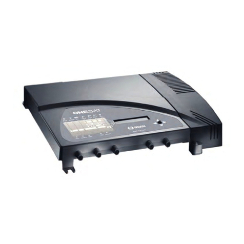
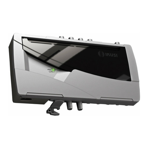
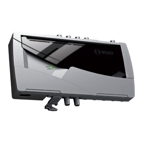
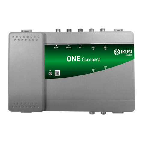
IKUSI 2844 User manual

Programmable multichannel amplifier
ONE
SAT / 118 / Home
REF. 2844 / 2845 / 2849
User Guide

29
30 General safety instructions
30 Types of notices
31 Basic safety instructions
32 Introduction
33 General description
33 Main features
34 General equipment use
36 Equipment installation and configuration
36 Installation
36 Power connection
37 Quick menu guide
38 Language selection
38 Manual setting
41 Advanced settings
43 Self-installation
45 Maintenance
45 Equipment care
45 Troubleshooting
46 Technical specifications
46 ONE 118 Model (AFP-201)
47 ONE SAT Model (AFP-292)
48 ONE Home Model (AFP-HOME)
49 Technical annex
50 Warranty
51 Equipment recycling
52 CE Certificate
EN
Contents

30
General safety instructions
JJReadJallJofJthisJuserJmanualJcarefullyJbeforeJpluggingJinJtheJequipment.
JJAlwaysJhaveJtheseJinstructionsJtoJhandJduringJinstallation.
JJFollowJallJofJtheJinstructionsJandJsafetyJnoticesJregardingJequipmentJhandling.
Types of notices
TheJmeaningJofJtheJsafetyJnoticesJusedJinJthisJmanualJareJdescribedJbelow.
DANGER OF DEATH OR INJURY
ThisJsafetyJnoticeJindicatesJaJpossibleJdangerJforJtheJlifeJandJhealthJofJpeople.J
NotJfollowingJtheseJinstructionsJmayJleadJtoJseriousJconsequencesJtoJhealthJandJ
mayJevenJcauseJfatalJinjuries.
RISK OF EQUIPMENT DAMAGE
ThisJsafetyJnoticeJindicatesJaJpossibleJdangerousJsituation.JNotJfollowingJtheseJ
instructionsJmayJleadJtoJtheJequipmentJbeingJdamaged.
NOTE
ThisJtypeJofJnoticeJisJaJnoteJcontainingJapplicableJadviceJandJusefulJinformationJ
forJoptimumJuseJofJtheJequipment.
HANDLING THE INSIDE OF THE EQUIPMENT IS FORBIDDEN
ThisJnoticeJforbidsJanyJworkJthatJmayJaffectJtheJworkingJorderJofJtheJequipmentJ
orJitsJwarranty.
DO NOT DISPOSE OF AS URBAN WASTE
ThisJtypeJofJnoticeJindicatesJthatJtheJequipmentJmustJnotJbeJdisposedJofJasJ
unselectedJurbanJwaste.
DANGER
ATTENTION

General safety instructions / Basic safety instructions
31
Basic safety instructions
DANGER OF DEATH OR INJURY
JJDoJnotJinstallJtheJequipmentJduringJanJelectricalJstorm.JThisJcouldJleadJtoJ
electrostaticJdischargeJfromJlightning.
JJDoJnotJopenJtheJequipment.JThisJcouldJleadJtoJelectricJdischarge.
RISK OF EQUIPMENT DAMAGE
JJTheJequipmentJmustJbeJappropriatelyJventilated.JInstallJtheJequipmentJinJaJ
dust-freeJlocation.JDoJnotJplaceJtheJequipmentJinJaJlocationJwhereJtheJventi-
lationJslotsJareJcoveredJorJblocked.JInstallJtheJequipmentJinJaJlocationJwithJatJ
leastJ20JcmJaroundJitJfreeJofJotherJobjects.
JJDoJnotJexposeJtheJequipmentJtoJrainJorJmoisture.JInstallJtheJequipmentJinJ
aJdryJlocationJwithJnoJinltrationJorJcondensationJofJwater.JShouldJaJliquidJ
enterJtheJequipment,JdisconnectJitJimmediatelyJfromJtheJmains.
JJKeepJtheJequipmentJawayJfromJammableJobjects,JcandlesJandJanythingJ
thatJmayJcauseJaJre.
JJConnectJtheJequipmentJtoJanJeasilyJaccessibleJpowerJsocket.JInJtheJeventJofJ
anJemergency,JitJwillJthenJbeJpossibleJtoJquicklyJunplugJtheJequipment.
JJDoJnotJexposeJtheJequipmentJtoJsourcesJofJheatJ(sun,Jheating,Jetc.).
DANGER
ATTENTION
EN

32
Introduction
General description
Main features
TheJONEJ118,JONEJSATJandJONEJHomeJmodelsJareJprogrammableJamplicationJheadendsJ
designedJtoJselectivelyJlterJanalogueJandJdigitalJUHFJchannels.JSuitableJforJsingle-familyJ
andJcollectiveJdwellings,JtheyJareJtheJidealJsolutionJforJmanagingJsignalsJofJdifferentJfre-
quenciesJandJbandwidths.J
FMJandJVHFJsignalsJareJalsoJamplied.JTheJONEJSATJmodelJalsoJampliesJsatelliteJIFJsig-
nals.JIndividualJadjustmentJofJeachJfrequencyJlter,JnumberJofJchannelsJandJautomaticJgainJ
controlJallowsJforJlevelJequalizeJofJselectedJchannels.
JJProgramming:
JFSelf-installationJfunction.
JFAllJsettingsJareJautomaticallyJmemorised.
JFNoJexternalJprogrammerJrequired,JprogrammedJdirectlyJfromJtheJheadend.
KEY
1 BI-FMJinput
2 BIII-DABJinput
3 VHF-UHF/EXTJinputJ*
4 UHF3Jinput
5 UHF2Jinput
6 UHF1Jinput
7 SAT-IF1JinputJ*
8 MainsJconnector
9 ControlJbutton
10 ScreenJ(LCD)
11 FrontJpanelJwithJclusterJmap
12 SAT-IF2JinputJwithJnoJamplicationJ*
13 OutputJ2;JTV+SAT2J*
14 OutputJtestJ2*
15 OutputJtestJ1J
16 OutputJ1;JTV+SAT1J**
17 Earthing
*JJONEJSATJmodelJonly
**JJJJInJONEJ118JmodelJTVJonly

33
Introduction / Main features
JFReprogrammableJasJmanyJtimesJasJrequired.
JJ10JtuneableJUHFJltersJwithJtheJcapacityJtoJprocessJ1JtoJ5JchannelsJeach.
JJSignalJprocessing:
JFTerrestrialJinputsJwithJlowJnoiseJgureJ(<J6JdB).
JFSatelliteJinputJwithJlowJnoiseJgureJ(<J9JdB).
JFAutomaticJsignalJlevelJequalisation.
JFAutomaticJgainJcontrol.
JJExtraJfunctions:
JFInternalJcongurationJcloningJwithJtransferralJtoJanotherJequipment.
JFEquipmentJlockingJbyJsecurityJcode.
JJDimensionsJ:J290JmmJxJ240JmmJxJ20Jmm
JJWeightJ:J2Jkg
TheJmainJfeaturesJofJtheJONEJ118JandJONEJSATJmodelsJareJdescribedJbelow.
ONE 118 Model
RecommendedJforJsmallJandJmedium-sizedJinstallationsJmadeJupJofJ10JUHFJltersJdeli-
veringJanJoutputJlevelJofJ118JdBμV.
JJInputs:
JF5JterrestrialJinputsJ=JBI-FM,JBIII-DAB,JUHF1,JUHF2,JUHF3.
JFBI-FMJgainJ=J35JdB.
JFBIII-DABJgainJ=J40JdB.
JFUHFJgainJ=J55JdB.
JJOutputs:
JF1JTVJoutput.
JF1JTestJoutput.
JFVHF/UHFJoutputJJlevelJ=J118JdBµV.J1
1JIMD3-60JdB,JDINJ45004BJ(seeJchannelJreductionJtableJinJTechnicalJAnnex)
ONE SAT Model
RecommendedJforJsmallJandJmedium-sizedJinstallations,JcomprisingJ10JUHFJltersJitJin-
cludesJoneJsatelliteJinputJandJtwoJmixedJtelevision-satelliteJoutputs.JCTIJcompliant.
CompatibleJwithJUNICABLEJTM
JJInputs:
JF6JterrestrialJinputs=JBI-FM,JBIII-DAB,JUHF1,JUHF2,JUHF3,JVHF-UHF/EXT.
JF2JsatelliteJIFJinputs.
JFBI-FMJgainJ=J30JdBJ(2Joutputs)JorJ35JdBJ(1Joutput).
JFBIII-DABJgainJ=J35JdBJ(2Joutputs)JorJ40JdBJ(1Joutput).
JFUHFJgainJ=J55JdBJ(2Joutputs)JorJ60JdBJ(1Joutput).
JFVHF-UHF/EXTJgainJ=J35JdBJ(2Joutputs)JorJ40JdBJ(1Joutput).
EN

34
Introduction / General equipment use
JFSAT1JgainJ=J40JdB.
JFSAT2JgainJ=J-1.5JdB.
JJOutputsJ(2JcongurableJoutputs):
a)
JF2JTV+FIJoutputs
JF2JTestJoutputs
JFVHFJoutputJlevelJ=J113JdBµV.1
JFUHFJoutputJlevelJ=J118JdBµV.1
JFFI/SATJoutputJlevelJ=J116JdBμV.2
J b)
JF1JTV+FIJoutput
JF1JTestJoutput
JFVHFJoutputJlevelJ=J118JdBµV.1
JFUHFJoutputJlevelJ=J123JdBµV.1
JFFI/SATJoutputJlevelJ=J116JdBμV.2
1JTerrestrial:JIMD3-60JdB,JDINJ45004B
2JSatellite:JIMD3J-35dB,JEN50083-3.JSeeJchannelJreductionJtableJinJTechnicalJAnnex
ONE Home Model
RecommendedJforJsmallJinstallationsJmadeJupJofJ10JUHFJltersJdeliJveringJanJoutputJlevelJ
ofJ118JdBμV.
JJInputs:
JF2JterrestrialJinputsJ=JBI-FM,JUHF1
JFBI-FMJgainJ=J2JdB.
JFUHFJgainJ=J40JdB.
JJOutputs:
JF1JTVJoutput.
JF1JTestJoutput.
JFVHF/UHFJoutputJJlevelJ=J113JdBµV.J1
1JIMD3-60JdB,JDINJ45004BJ(seeJchannelJreductionJtableJinJTechnicalJAnnex)
General equipment use
InteractionJwithJtheJequipmentJusingJtheJbuttonJandJtheJinterpretingJofJtheJinstructionsJ
displayedJonJtheJLCDJscreenJareJdescribedJbelow.JTheJprogrammeJincludesJaJmainJmenuJ
formedJbyJsubmenusJthatJcanJbeJselectedJtoJmodifyJtheJequipmentJoperatingJsettings.
Instructions displayed on the LCD screen
ThisJsymbolJisJdisplayedJwhenJmanualJsettingJisJselected.JItJrefersJtoJtheJ
clustersJindicatedJonJtheJpanel.

35
Introduction / General equipment use
ThisJsymbolJisJdisplayedJinJtheJmanualJsettingJmenu.JVisuallyJlocateJitJonJ
theJLCDJscreenJandJseeJtheJclusterJmapJonJtheJpanelJtoJseeJwhichJofJtheJ
5JequipmentJclustersJisJselected.
ThisJacronymJisJdisplayedJinJtheJmainJmenu.JSelectJitJtoJgoJbackJtoJtheJ
languageJselectionJmenu.
ThisJsymbolJisJdisplayedJinJmanualJsettingsJandJadvancedJsettingsJandJ
visuallyJindicatesJtheJpossibilityJofJmovingJvertically.
ThisJsymbolJisJdisplayedJinJmanualJandJadvancedJsettingsJandJalwaysJ
includesJaJnumericJvalueJandJvisuallyJindicatesJtheJgainJlevel.
ThisJiconJisJdisplayedJwhenJtheJequipmentJlockJisJenabledJwhenJtheJ
equipmentJisJswitchedJonJandJafterJperiodsJwhenJtheJequipmentJisJnotJinJ
use.
Vertical button movement
InJtheJmenusJandJsubmenus,JmoveJtheJbuttonJupJorJdownJtoJbrowseJ
upwardsJandJdownwardsJpositionJbyJposition.
InJtheJsettings,JmoveJtheJbuttonJupJorJdownJtoJmodifyJvaluesJpositionJbyJ
position.
NOTE
KeepJtheJbuttonJpressedJupJorJdownJtoJbrowseJorJtoJmodifyJ
valuesJmoreJquickly.
Horizontal button movement
InJtheJmenus,JmoveJtheJbuttonJtoJtheJleftJorJtheJrightJtoJselectJandJgoJ
backJpositionJbyJposition.
InJtheJsettings,JmoveJtheJbuttonJtoJtheJleftJorJtheJrightJtoJbrowse,JselectJ
andJgoJbackJpositionJbyJposition.
NOTE
KeepJtheJbuttonJpressedJtoJtheJleftJorJtoJtheJrightJtoJbrowseJ
moreJquickly.
Press button
InJtheJmenus,JthisJselectsJtheJsubmenu.
InJtheJsubmenus,JthisJselectsJtheJsetting.
InJtheJsettings,JthisJselectsJtheJparameterJvalue.
▲
▼
EN

36
Equipment installation and configuration / Installation
Equipment installation and configuration
OnlyJtheJLCDJscreenJandJtheJbuttonJareJrequiredJtoJcongureJtheJequipment.JFollowJtheJ
stepsJbelowJtoJinstallJtheJequipmentJandJcongureJtheJdifferentJparameters.
Installation
RISK OF EQUIPMENT DAMAGE
MechanicalJhandlingJofJtheJequipmentJ
whileJitJisJswitchedJonJmayJleadJtoJitJ
beingJdamaged.JDoJnotJplugJtheJequi-
pmentJintoJtheJmainsJbeforeJorJduringJ
installation.
1) FitJandJtightenJtheJboltsJandJplugsJsecuringJ
theJequipmentJtoJtheJwall.
2) ConnectJtheJcoaxialJcableJfromJtheJaerialJtoJ
theJequipment.
3) ConnectJtheJcoaxialJcablesJfromJtheJoutputsJ
toJtheJequipment.J
IfJonlyJoneJofJtheJ2JoutputsJisJused,JterminateJ
theJspareJportJwithJaJ75ΩJloadplug.
Power connection
DANGER OF DEATH OR INJURY
IncorrectJequipmentJpowerJconnectionJ
mayJcauseJanJelectricJshock.JFollowJtheJ
stepsJbelowJforJtheJelectricalJinstallationJ
ofJtheJequipment.
1) ConnectJtheJgroundJcable.
2) ConnectJtheJpowerJplugJtoJtheJequipmentJ
mainsJconnector.
3) ConnectJtheJpowerJplugJtoJtheJmainsJsocket.
ATTENTION
+12V
5A
POWER
QPSK IN
RF OUT
QPSK IN
RF OUT
QPSK IN
RF OUT
QPSK IN
RF OUT
SRF-111
SRF-111
SRF-111
SRF-111
SRF-111
+24V
+18V
+13V
+18V
+13V
:700 mA
INPUT
OUTPUT
AUX INPUT
GAIN
OUTPUT TEST
ON
INPUT TEST
HPA-120
+12V
5A
POWER
QPSK IN
RF OUT
QPSK IN
RF OUT
QPSK IN
RF OUT
QPSK IN
RF OUT
SRF-111
SRF-111
SRF-111
SRF-111
SRF-111
+24V
+18V
+13V
+18V
+13V
:700 mA
INPUT
OUTPUT
AUX INPUT
GAIN
OUTPUT TEST
ON
INPUT TEST
HPA-120
+12V
5A
POWER
QPSK IN
RF OUT
QPSK IN
RF OUT
QPSK IN
RF OUT
QPSK IN
RF OUT
SRF-111
SRF-111
SRF-111
SRF-111
SRF-111
+24V
+18V
+13V
+18V
+13V
:700 mA
INPUT
OUTPUT
AUX INPUT
GAIN
ON
HPA-120
DANGER

37
Equipment installation and configuration / Fast menu guide
Language
selection
(10-0-0)
(7-0-3)
Filter allocation
to aerials
(9-0-1)
(2-5-3)
(2-7-1)
General
gain
BI - BII input BIII-DAB input
UHF output VHF-UHF/EXT
input
SAT-IF adjustment
Self-installation
Input preamps
Lock
Equipment
information
Restore
values
cloning
Manual setting Advanced settings
Frequency
plan
Outputs numbers
conguration
Filter Adjustment
OUTPUT CONF
TV2 & TV1
Automatic
Gain Control
A.G.C.
OFF
Fast menu guide EN

38
Equipment installation and configuration / Quick menu guide
Quick menu guide
Language selection
NOTE
OverJtheJfollowingJpages,JtheJeldJlocatingJandJselectionJmethodJisJprimarilyJ
indicatedJbyJtheJ“verticalJbuttonJmovement”JandJ“pressJbutton”Jicons.JHowever,J
horizontalJbuttonJmovementJcanJbeJusedJtoJlocateJandJselectJelds,JasJindicatedJ
inJtheJGeneral equipment useJsectionJonJPageJ34.
NOTE
TheJequipmentJautomaticallyJaccessesJlanguageJselectionJaJfewJsectionsJafterJ
theJwelcomeJmessageJisJdisplayed.JLanguageJselectionJcanJalsoJbeJaccessedJbyJ
goingJbackJfromJtheJmainJmenu.
1) LocateJandJselectJtheJlanguage:JESPAÑOL –
ENGLISH – FRANÇAISE.
2) AccessJtheJmainJmenu.
Manual setting
1) InJtheJmainJmenu,JlocateJandJselectJMANUAL.
NOTE
TheJclusterJmapJonJtheJequipmentJpanelJ
indicatesJtheJclusterJrelatedJtoJeachJsub-
menu.
Filter allocation to aerials
NOTE
ThereJareJveJdifferentJcongurationsJtoJ
distributeJtheJ10JltersJamongJtheJ3Jaerials.
1) LocateJandJselectJtheJaerialJlterJcongurationJ
(theJaerialJdistributionJisJdisplayedJatJtheJtopJ
ofJtheJscreenJandJtheJ10JltersJavailableJareJ
displayedJatJtheJbottom):
JJForJoneJaerial:
a)J CongurationJ(10J–J0J–J0)

39
Equipment installation and configuration / Manual setting
JJForJtwoJaerials:
b)J CongurationJ(9J–J0J–J1)
c)J CongurationJ(7J–J0J–J3)
JJForJthreeJaerials:J
d)J CongurationJ(2J–J5J–J3)
e)J CongurationJ(2J–J7J–J1)
Mast-head amplifier power configuration
NOTE
OnlyJwhereJaJmast-headJamplierJisJttedJ
toJtheJaerial.
1) LocateJandJselectJtheJUHFJinputJvoltage:JVDC,
24 / 12.
2) LocateJandJselectJUHFJinputJvoltageJenablingJ
(ON)J/JdisablingJ(OFF):
a)J UHF3JinputJvoltage:JΨ3, ON / OFF
b)J UHF2JinputJvoltage:JΨ2, ON / OFF
c)J UHF1JinputJvoltage:JΨ1, ON / OFF
Filter adjustment
Frequency configuration
1) LocateJandJselectJtheJlterJtoJadjust:J
FIL, 1 – 10.
2) LocateJandJselectJtheJlterJstartJchannel:J
BEG, 21 – 69.
3) LocateJandJselectJtheJlterJendJchannel:J
END, 21 – 69.
EN

40
Equipment installation and configuration / Manual setting
Gain configuration:
NOTE
IfJAUTJisJselectedJ(recomended),JtheJAGCJ
willJtryJandJmaintainJtheJoutputJatJfactoryJ
presetJlevel.JIfJMJisJselectedJtheJAGCJwillJ
maintainJtheJoutputJatJtheJlevelJyouJhaveJ
set.
1) LocateJandJselectJtheJgainJcongurationJmodeJ
AUT / M.
a)J IfJAUTJisJselected:Jself-equalisingJisJ
congured.
b)J IfJMJisJselected:JlocateJandJselectJtheJgainJ
levelJ00 – 30.
General gain adjustment
1) LocateJandJselectJtheJgainJsubmenu:
2) LocateJandJselectJtheJgainJlevel:
a)J BIJ-JBIIJinput:JBI_BII, 0 - 25
b)J BIIIJ-JDABJinput:JBIII_DAB, 0 - 20
c)J VHF-UHF/EXTJinput:JVHF_UHF, 0 - 20
d)J UHFJoutput:JUHF, 0 - 20

41
Equipment installation and configuration / Advanced settings
SAT-IF output adjustment
LNB power configuration
NOTE
ThereJareJ5JdifferentJcongurationsJtoJ
selectJpolarisation.J
1) LocateJandJselectJpolarisation:
a)J NoJpolarisation:JLNB, OFF.
b)J 18JVJwithJtones:JLNB, 18 V.
c)J 18JVJwithoutJtones:JLNB, 18 V.
d)J 13JVJwithJtones:JLNB, 13 V.
e)J 13JVJwithoutJtones:JLNB, 13 V.
Output gain configuration:
1) LocateJ
GA
JandJselectJlevelJ0 - 20.
Emphasis among high frequencies
NOTE
IfJTILTJisJselected,JtheJequipmentJappliesJ
9JdBJofJpre-emphasises.
1) LocateJandJselectJTILTJtoJchangeJtheJlevelJofJ
pre-emphasisJbetweenJ0JandJ9JdB.
Advanced settings
1) InJtheJmainJmenu,JlocateJandJselectJ
ADVANCED.
Input preamps
NOTE
TheJgainJdifferenceJbetweenJanJenabledJandJaJdisabledJamplierJisJ20JdB.JSelectJ
LOJtoJenableJanJamplier.J
IfJtheJgainJisJsetJtoJautomaticJinJlterJconguration,JtheJsystemJmanagesJpreampJ
enablingJaccordingJtoJtheJinputJlevel.
1) LocateJandJselectJUHFJinputJpreamps:
a)J UHF3Jinput:JΨ3, HI / LO.
EN

42
Equipment installation and configuration / Advanced settings
b)J UHF2Jinput:JΨ2, HI / LO.
c)J UHF1Jinput:JΨ1, HI / LO.
Equipment configuration cloning
NOTE
CloningJbeginsJautomaticallyJafterJtheJ
followingJsteps.
1) ConnectJtwoJequipmentsJusingJaJcoaxialJcableJ
inJtheJTestJ1JoutputJofJeachJequipmentJ(seeJ
positionJ(15)JinJtheJillustrationJinJtheJGeneral
DescriptionJsectionJonJpageJ32).
2) OnJtheJequipmentJreceivingJtheJinformation:J
locateJandJselectJMASTER OFF, SLAVE ON.
3) OnJtheJequipmentJsendingJtheJinformation:J
locateJandJselectJMASTER ON, SLAVE OFF.
NOTE
TheJtimeJwaitedJforJcloningJtoJbeJrunJisJ11J
seconds.JWhereJcloningJcannotJbeJstarted,J
theJequipmentJreturnsJtoJtheJhigherJmenu.
Equipment locking
NOTE
TheJlockJisJenabledJwhenJtheJequipmentJisJ
re-connected.J
1) EnterJaJsequenceJofJ4JdigitsJ(LOCK, 0000).
2) LocateJandJselectJLOCK, ON.
NOTE
ToJunlockJtheJequipment,JenterJandJselectJ
theJ4-digitJsequenceJonJtheJstartJscreen.J
ToJcancelJequipmentJlocking,JlocateJandJ
selectJLOCK, OFF.JIfJyouJforgetJtheJ
4-digitJsequenceJsee:JTroubleshootingJ
sectionJonJpageJ45.

43
Equipment installation and configuration / Advanced settings
Specific equipment information
NOTE
InformationJonJtheJequipment,JtheJpro-
grammeJversion,JtheJmanufacturingJdate,J
theJnumberJofJhoursJoperating,JtheJtem-
peratureJandJtheJequipmentJserialJnumberJ
areJdisplayedJonJtheJscreen.
Restore factory values
CAUTION
ThisJfunctionJwillJmeanJthatJallJpreviousJ
congurationsJwillJbeJlostJandJtheJfactoryJ
valuesJwillJbeJrestored.
1) SelectJOKJtoJrestoreJfactoryJvalues.J
Frequency plan
NOTE
YouJcanJchooseJbetweenJtwoJdifferentJ
channelJallocationsJforJtheJUHFJband.J
TheseJallocationsJdependJonJtheJgeo-
graphicJterritory.JBy default the equip-
ment is configured for the European
allocation.
1) InJtheJadvancedJmenu,JlocatedJandJselect
FREQUENCY PLAN.
a)J IfJEUROPEJisJselectedJtheJchannelJalloca-
tionJisJforJEuropeanJstandards.
b)J IfJAUSTRALIANJisJselectedJtheJchannelJ
allocationJisJforJAustralianJstandard.
Automatic Gain Control
NOTE
YouJcanJchooseJtoJactivateJtheJautomaticJ
gainJcontrol.JBy default the equipment is
configured in OFF position.
1) LocateJandJselectJA.G.C.JinJONJposition.
A.G.C.
OFF
EN

44
Equipment installation and configuration / Advanced settings
Outputs number configuration
NOTE
YouJcanJchooseJtwoJtypesJofJcongurationJ
forJOutputsJNo:JTV2J&JTV1JorJTV1.J
By default your equipment is configu-
red for two outputs (TV1 & TV2).
1) InJtheJadvancedJmenu,JlocatedJandJselectJ
OUTPUT CONFIGURATION TV2&TV1.
a)J OUTPUTJCONFJTV2J&JTV1Jselect.
b)J OUTPUTJCONFJJTV1Jselect.
Self-installation
NOTE
TheJequipmentJautomaticallyJconguresJtheJoptimumJoperatingJfrequencyJandJ
gainJofJtheJUHFJlters.JThe equipment does not automatically configure the
output level of general (band) gains.JThisJisJbecauseJtheJoutputJlevelJmustJbeJ
setJbyJtheJinstallerJtoJsuitJtheJnetworkJyouJareJfeeding.
1) InJtheJmainJmenu,JlocateJandJselectJ
AUTOINSTALL.
a)J IfJNOJisJselected:JyouJwillJreturnJtoJtheJ
mainJmenu.
b)J IfJYESJisJselected:Jself-installationJwillJ
begin..
NOTE
TheJequipmentJdisplaysJinformationJonJ
theJstatusJofJself-installation.JPleaseJ
waitJaJfewJsecondsJuntilJitJisJcompletedJ
andJAUTOINSTALL COMPLETEDJisJ
displayed.
2) SelectJOKJtoJcompleteJself-installation.JTheJ
unitJwillJnowJshowJyouJtheJgeneralJ(band)JgainJ
settingsJforJadjustment.
3) ToJchangeJtheJoutputJlevelJofJgeneralJgains,J
see:JGeneral gain adjustmentJsectionJonJpageJ
40.
4) ToJreviewJtheJallocationJofJltersJtoJaerials,Jsee:J
Allocation of filters to aerialsJsectionJonJPageJ
38.
TV1
TV2 & TV1

45
Maintenance
Equipment care
HANDLING THE INSIDE OF THE EQUIPMENT IS FORBIDDEN
DoJnotJdismantleJorJtryJtoJrepairJtheJequipment,JitsJaccessoriesJorJitsJcompo-
nents.JThisJwillJrenderJtheJwarrantyJnullJandJvoid.
JJDoJnotJuseJtheJpowerJcableJifJitJisJdamaged.
JJToJdisconnectJtheJpowerJcable,JpullJcarefullyJonJtheJplugJandJnotJtheJcable.
JJToJcleanJtheJpanelJandJequipmentJconnections:
JFUnplugJtheJequipment.
JFCleanJwithJaJslightlyJdamp,JsoftJcloth.J
JFAllowJtoJdryJcompletelyJbeforeJuse.
JJDoJnotJspillJliquidJontoJtheJequipment.J
JJKeepJventilationJslotsJfreeJofJdustJandJanyJforeignJbodies.
Troubleshooting
TheJmostJfrequentJproblemsJarisingJduringJequipmentJinstallationJareJindicatedJbelow.JIfJ
youJencounterJanyJotherJtypeJofJproblem,JpleaseJcontactJtheJequipmentJsalesJteam.
Problem Possible cause What to do
ForgottenJunlockJcode. - ContactJyourJpointJofJsale.
NothingJdisplayedJonJ
LCDJscreen.
TheJpowerJcableJisJnotJcon-
nectedJproperly.J
CheckJtheJpowerJcable.
TheJchannelsJdoJnotJ
adjustJtoJtheJprogrammedJ
outputJlevel.
LackJofJsignalJorJunsuitableJ
channelJlevel.
CheckJthatJtheJchannelJ
programmedJinJtheJhighestJ
outputJchannelJhasJaJsignalJandJ
appropriateJlevel.JThisJisJusedJ
asJaJreferenceJforJoutputJlevelJ
adjustment.
EN

46
Technical specifications
ONE 118 Model (AFP-201)
Inputs BI-FM
1
BIII-DAB
1
UHF1 UHF2 UHF3
3
BandJwidth MHz 47-108 174-240 470-862
InputJconguration
NumberJofJprogrammableJUHFJ
ltersJperJinput
- - J 10J 0J 0
- - J 9J 0J 1
- - J 7J 0J 3
- - J 2J 5J 3
- - J 2J 7J 1
GainJ dB 35 40 35J/J55
(switchable)
GainJadjustment dB 25 20 30
NoiseJgure dB <6 <6 <6
OptimumJinputJmargin dBµV 60-85 60-80 50-80J
70-100
ReturnJlosses dB >10 >10 >10
SelectivityJ
(±J10JMHzJofJchannelJends)
dB >10
UncouplingJbetweenJinputs dB - - >20
AGCJtolerance dB - - ±1
SwitchableJpreampJvoltage V - - 0-12-24
MaximumJpreampJcurrent mA - - 100
Output TV
OutputJlevel* dBµV 118 118 118
OutputJlevelJadjustment dB 20
ReturnJlosses dB >10
TestJoutputs dB -30
Operations
MainsJvoltage 230J-J240JV~
Consumption 0.25JAJ/J25JW
OperatingJtemperature -5JtoJ50JºC
MainsJconnector IECJC8
*JIMD3-60dB,JDINJ45004B
JJ(SeeJchannelJreductionJtableJinJTechnicalJAnnex)

Technical specifications / ONE SAT Model (AFP-292)
47
ONE SAT Model (AFP-292)
Inputs BI-FM
1
BIII-DAB
1
UHF1 UHF2 UHF3
3
EXT
(VHF/UHF)
1
SAT-IF
1
FI-SAT
(passive)
1
BandJwidth MHz 47-108 174-240 470-862
47-240J/J
470-862
950-
2150 950-
2150
InputJconguration
NumberJofJprogrammableJ
UHFJltersJperJinput
- - J 10J 0J 0 - - -
- - J 9J 0J 1 - - -
- - J 7J 0J 3 - - -
- - J 2J 5J 3 - - -
- - J 2J 7J 1 - - -
GainJ TV1&TV2Jconf
TV1Jconf
dB
30 35 35/55
J(switchable)
35 40 -1.5
35 40
40/60J
(switchable)
40 40
GainJadjustment dB 25 20 30 20 20 -
NoiseJgure dB <6 <6 <6 <6 <9 -
OptimumJinputJ
margin dBµV 60-85 60-80 50-80J
70-100 60-80 68-88 -
ReturnJlosses dB >10 >10 >10 >10 >10 >10
SelectivityJ(±J10JMHzJ
ofJchannelJends)
dB >10 - - -
UncouplingJJ
betweenJinputs dB - - >20 - - -
AGCJtolerance dB - - ±1 - - -
SwitchableJpreampJ
voltage V - - 0-12-24 - 0-13-18 -
MaximumJpreampJ
current mA - - 100 - 300 -
PreampJtones kHz - - - - 0-22 -
SlopeJadjustment dB - - - - 0-9 -
Outputs (2 options) TV+IF
Output
level*J
TV1&TV2Jconf
TV1Jconf dBµV 113 113 118 113/118 116 -
118 118 123 113/123 116
OutputJlevelJ
adjustment dB J JJ20 -
ReturnJlosses dB J >10 -
TestJoutputsJ(2) dB J -30
Operations
MainsJvoltage 230J-J240JV~
Consumption 0.25JAJ/J25JW
OperatingJtemperature -5JtoJ50JºC
MainsJconnector IECJC8
*JTerrestrial:JIMD3-60dB,JDINJ45004BJJ;JJSatellite:JIMD3J-35dB,JEN50083-3.
JJJ(SeeJchannelJreductionJtableJinJTechnicalJAnnex)
EN
This manual suits for next models
5
Table of contents
Other IKUSI Amplifier manuals

IKUSI
IKUSI ONE+ SAT User manual

IKUSI
IKUSI ONE SAT User manual

IKUSI
IKUSI NBS-801-C69 User manual

IKUSI
IKUSI ONE 118 User manual

IKUSI
IKUSI One Sat 118 User manual

IKUSI
IKUSI NBS-800 Series User manual
IKUSI
IKUSI One Sat 118 User manual

IKUSI
IKUSI ONE Series User manual

IKUSI
IKUSI NBS-801-C48 User manual

IKUSI
IKUSI SBA-103-C60 User manual

IKUSI
IKUSI NBS-800 Series User manual

IKUSI
IKUSI NBS-600 Series User manual

IKUSI
IKUSI ONE SAT User manual

IKUSI
IKUSI One Sat 123 User manual

IKUSI
IKUSI SRF Series User manual

IKUSI
IKUSI NBS-200 User manual

IKUSI
IKUSI ATP-900 User manual

IKUSI
IKUSI MB-01 User manual

IKUSI
IKUSI NBS-600 Series User manual
IKUSI
IKUSI NBS-200 Series User manual