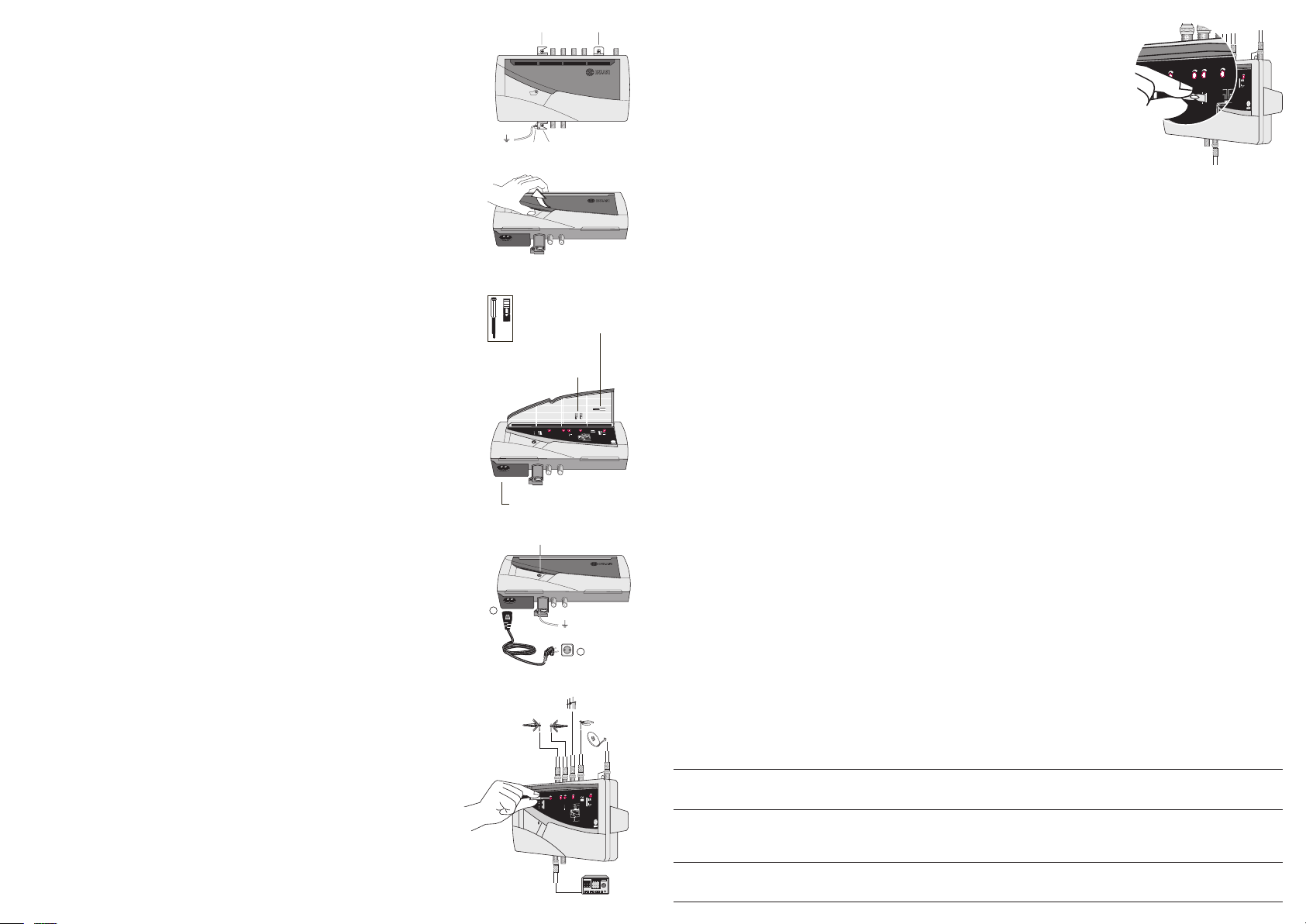
1. Крепление к стене и заземление.
Усилитель крепится к стене с помощью трех шурупов (Т):
1.Закрепить Т1 в стене, не закручивая до конца. Подвесить корпус за верхнее ушко.
2. Выровнять положение корпуса и закрутить Т2 и Т3.
3. Затянуть Т1.
Для заземления корпуса используется шуруп Т4 в нижней части корпуса.
1. Wall xing and grounding
The amplier is xed using the thee screws (T) :
1. Place T1 on the wall, not tightening. Hang the housing through the upper holder.
2. Put straight the housing and tighten T2 and T3.
3. Tighten T1.
To ground the housing use the T4 screw at the lower side.
1. Fixation au mur et mise à la terre
L’amplicateur se xe au mur au moyen des trois vis (T) :
1. Placer T1 sur le mur, sans le serrer. Pendre le boîtier par l’ouïe supérieure.
2. Poser droit le boîtier et serrer T2 et T3.
3. Serrer T1.
Pour la mise à la terre du boîtier utiliser la vis située au côté inférieur (T4).
2. Открытие декоративной крышки корпуса.
Открыть крышку, как показано на рисунке справа. В нижней части крышки находятся
отвертка для настройки и перемычки для переключения под-диапазонов ДМВ.
2. Openning the housing
Remove the lid as shown in the gure on the right. One setting shaft and one plug-in birdge are
tted on the back side of this cover.
2. Ouverture du boîtier
Retirez le couvercle comme montré dans la gure de droite. Au derrière de ce couvercle est logé
un axe de réglage ainsi que, un pont enchable pour séleccionner la fréquence UHF.
3. Подключение к сети переменного тока.
Неправильное подключение к сети переменного тока может спровоцировать электрический
удар. Выполните следующие шаги для подключения изделия к сети переменного тока:
1. Подсоедините сетевой кабель к сетевому разъему усилителя.
2. Подключите вилку кабеля к розетке сети переменного тока. Индикатор ON
загорится зеленым светом
3. Mains connection
Incorrect unit power connection may cause an electric shock. Follow the steps below for the
electrical installation of the unit.
1. Connect the power plug to the unit mains connector.
2. Connect the power plug to the mains socket. The ON led lights up green.
3. Raccordement secteur
Un branchement incorrect de l’alimentation de l’équipement peut provoquer des décharges électri-
ques. Suivre les étapes suivantes pour installer l’équipement électriquement.
1. Brancher la base du câble de réseau au connecteur de réseau de l’équipement.
2. Brancher la prise du câble de réseau à celle du courant électrique. La led ON s’illumine
verte.
4. Регулировка уровня выходного сигнала и “наклона” характеристики.
Подключить измеритель уровня. Затем, используя поставляемую регулировочную
отвертку, вращая поочередно потенциометры, добиться требуемого уровня (сумма
требуемого уровня сигнала на выходе ТВ-розетки и величины потерь распределения).
Если какой-либо вход не используется, настроить соответствующий ему потенциометр на
минимальный уровень усиления.
В модели NBS-695 регулировка наклона производится установкой
перемычки(поставляется).
4. Setting-up the RF output level and slope range
Connect a level meter. Then, by using the shaft supplied, operate on each one of the setting
potentiometers to obtain the desired output signal level (sum of that required in the TV outlets plus
the distribution losses). If an input is not used, set for maximum attenuation the corresponding
potentiometer. IF slope control range (0-6dB) is provided by inserting a bridge supplied in NBS-
695 model.
4. Réglage du niveau HF de sortie et réglage de pente
Brancher un mesureur de niveau. Alors, en utilisant l’axe fourni, agir sur chacun des poten-
tiomètres de réglage pour obtenir le niveau désiré de sortie (somme de celui requis dans les prises
TV plus l’affaiblissement du réseau de distribution). Si une entrée n’est pas utilisée, régler à
l’atténuation maximale le correspondant potentiomètre. Dans le modèle NBS-695, le réglage de
pente BIS (0-6dB) est ajustée par l’insertion d’un pont enchable fourni.
Регулировочная отвертка
setting shaft
axe de réglage
Перемычка
plug-in bridges
ponts
5. Выбор частоты.
С помощью установки поставляемой перемычки можно выбрать верхнюю частоту
диапазона ДМВ между 790 и 862 MHz.
5. Frequency Selection
By inserting a bridge, you can select the cutoff frequency low-pass lter in the upper UHF,
switchable between 862 MHz and 790 MHz.
5. Sélection de Fréquence
En insérant un pont, vous pouvez choisir la fréquence de coupure du ltre passe-bas dans la
partie supérieure UHF, commutable entre 862 MHz et 790 MHz.
7. Техническое приложение. Таблица снижения выходного уровня в широкополосных усилителях.
Широкополосные усилители эфирного ТВ: уровни выхода RF, заявленные в техническом описании для комбинационных
искажений IMD3 с -60dB (DIN45004B), применимы, когда усиливают 2 аналоговых канала ТВ. Если, как в большинстве
случаев, усиливается более 2 каналов, эти уровни должны быть пересчитаны в соответствии со следующей таблицей.
Сигналы FM, DAB, DVB-T: если максимальные уровни сигналов эфирных радио FM, DAB и цифрового ТВ (DVB-T) устанавливаются на 10 dB ниже,
чем уровень аналоговых или менее; то в таком случае они могут не учитываться в расчетах по снижению вых. уровня, в противном случае должны
считаться как аналоговые ТВ сигналы.
Широкополосные усилители спутникового ТВ или цифрового эфирного ТВ:
выходной уровень усилителя для комбинационных искажений IMD3 с -42dB (EN50083-3) составляет 117 dB в случае, когда
усиливают 1 канал QPSK или COFDM. Если, как в большинстве случаев, усиливается большее число каналов, эти уровни должны
быть пересчитаны в соответствии со следующей таблицей:
7. Tehcnical Annex Output level reduction in broadband ampliers.
BROADBAND TERRESTRIAL TV AMPLIFIERS : The RF output levels specied in this user guide for IMD3=-60 dB (DIN 45004 B)
are applicable when 2 analog TV channels are amplied. If, as is usual, more than 2 TV channels are amplied, such levels have to be
reduced according to the following table:
FM, DAB AND COFDM SIGNALS : If output levels of the FM, DAB and Digital TV (COFDM) signals are adjusted 10 dB or more below the levels of the analog
TV channels, those signals can be ignored when calculating the output reduction level. If referred levels are not reduced as indicated, those signals must be
counted as normal channels and the output level de-rated accordingly.
BROADBAND SATELLITE TV OR DIGITAL TERRESTRIAL TV AMPLIFIERS : The RF output level for IMD3=-42 dB
(EN 50083-3) is 117dBμV are applicable when 1 QPSK or COFDM modulated TV digital channel is amplied. For a bigger number of
channels, such levels have to be reduced according to the following table:
7. Annexe Technique Réduction du niveau de sortie des amplicateurs large bande.
AMPLIFICATEURS LARGE BANDE TV TERRESTRE : Le niveau de sortie HF spécié pour une IM3 à -52 dB selon la Norme UTE
C90-125 correspond à l’amplication de 2 canaux TV analogiques. Pour plus de 2 canaux, le niveau de sortie doit être réduit conformé-
ment au tableau suivant :
SIGNAUX FM, DAB ET COFDM : Si les niveaux de sortie des signaux FM, DAB et TV Numérique (COFDM) sont d’environ 10 dB plus bas que les niveaux
des canaux TV Analogique, ils peuvent être négligés. À niveau égal, les compter comme des canaux analogiques.
AMPLIFICATEURS LARGE BANDE TV SATELLITE OU TV NUMÉRIQUE TERRESTRE : Le niveau de sortie HF pour une IM3 à
-42 dB selon la Norme EN 50083-3 est 117 dBμV correspond à l’amplication d’1 canal TV numérique modulation QPSK ou COFDM.
Pour plus d’1 canal, le niveau de sortie doit être réduit conformément au tableau suivant :
Количество аналоговых каналов (n)
Analog channels Number (n)
Nombre de canaux analogiques (n) 2 3 4 5 6 7 8 9 10 15 20
Понижение уровня выхода=7,5*log(n-1)
Output level reduction= 7,5 · log (n-1)
Réduction du niveau de sortie = 7,5 · log (n-1) dB 0 2 3,5 4,5 5 5,5 6 6,5 7 8,5 9,5
Количество цифровых каналов (n)
Digital channels number (n)
Nombre de canaux numériques (n) 2 3 4 5 6 7 8 9 10 15 20
Понижение уровня выхода=10*log(n-1)
Output level reduction= 10 · log (n)
Réduction du niveau de sortie = 10 · log (n) dB 3 4,5 6 7 8 8,5 9 9,5 10 11,5 13
Test
BI/FM
BIII/DAB
UHF
SAT
Ref. 3530
(TV+IF)
-30dB
6. Выбор питания подантенных усилителей.
Питание подантенных усилителей переключается посредством двух перемычек между 12 или 24 V.Модель NBS-695 имеет
возможность переключения 13V, 18 V и 22 kHz для
питания спутникового конвертора.
6. Power Supply selection
The voltage power supply for mast-head ampliers is switchable, by inserting two bridges, between 12 and 24V.
NBS-695 model has two linear voltage regulators, which provide voltages of 13 and 18 V, selectable with a bridge In addition there is an
oscillator that provides a 22 kHz signal, which modulates the amplitude regulators when selected.
6. Sélection de l’alimentation
L’alimentation du préamplicateurs de mât commute, par l’insertion de deux ponts, entre 12 et 24V.
NBS-695 modèle dispose de deux régulateurs de tension linéaires, qui fournissent des tensions de 13 à 18 V, sélectionnable par pont. En
outre, il est un oscillateur qui fournit un signal de 22 kHz, qui module l’amplitude de réglementation lorsqu’il est sélectionné.
Источник питания Съемный
removable power supply
alimentation extractible
IEC C8