IKUSI ONE ZERO User manual
ONE
Programmable terrestrial filtering header
User manual
ZERO
REF. 2848


4 General safety instructions
4 Types of notices
5 Basic safety instructions
6 Introduction
6 General description
6 Main features
7 General use of the unit
9 Unit installation and configuration
9 Installation
9 Power connection
10 Fast menu guide
11 Language selection
11 Manual setting
13 Advanced settings
15 Self-installation
16 Maintenance
16 Unit care
16 Troubleshooting
17 Technical specifications
17 ONE ZERO Model (FFP-110)
18 Technical appendix
19 Warranty
20 Unit recycling
21 CE Certificate
Contents
4
General safety instructions
JRead all of this user manual carefully before plugging in the unit.
JAlways have these instructions to hand during installation.
JFollow all of the instructions and safety notices regarding unit handling.
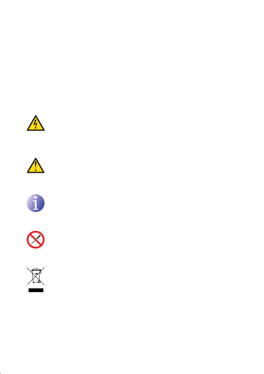
Types of notices
The meaning of the safety notices used in this manual are described below.
DANGER OF DEATH OR INJURY
This safety notice indicates a possible danger for the life and health of people.
Not following these instructions may lead to serious consequences to health and
may even cause fatal injuries.
RISK OF DAMAGE TO THE UNIT
This safety notice indicates a possible dangerous situation. Not following these
instructions may lead to the unit being damaged.
NOTE
This type of notice is a note containing applicable advice and useful information
for optimum use of the unit.
HANDLING THE INSIDE OF THE UNIT IS FORBIDDEN
This notice forbids any work that may affect the working order of the unit or its
warranty.
DO NOT DISPOSE OF AS URBAN WASTE
This type of notice indicates that the unit must not be disposed of as unselected
urban waste.
DANGER
ATTENTION

General safety instructions/Basic safety instructions
55
Basic safety instructions
DANGER OF DEATH OR INJURY
JDo not install the unit during an electrical storm. This could lead to electro-
static discharge from lightning.
JDo not open the unit. There is a risk of electrostatic discharge.
RISK OF DAMAGE TO THE UNIT
JThe unit must be appropriately ventilated. Install the unit in a dust-free
location. Do not place the unit in a location where the ventilation slots are
covered or blocked. Install the unit in a location with at least 20 cm around it
free of other objects.
JDo not expose the unit to rain or moisture. Install the unit in a dry location
with no water inltrations or condensation. Should a liquid enter the unit,
disconnect it immediately from the mains.
JKeep the unit away from ammable objects, candles and anything that may
cause a re.
JConnect the unit to an easily accessible power socket. In the event of an
emergency, it will then be possible to quickly unplug the unit.
JDo not expose the unit to sources of heat (sun, heating, etc.).
DANGER
ATTENTION
ENEN
6
Introduction
General description
Main features
The ONE ZERO model is a programmable terrestrial ltering header, designed to selectively
lter analogue and digital UHF channels. It is suitable for individual and collective dwellings
and it is the ideal solution to correctly equalise television channels that come through the
aerial with different frequencies and amplitudes.
The ONE ZERO model has 10 tuneable UHF lters that can process between 1 and 5 chan-
nels each. Individual adjustment of each frequency lter, number of channels and automatic
gain control allows for level equalisation of selected channels.
JProgramming:
FSelf-installation function.
FAll settings are automatically memorised.
FNo external programmer required, programmed directly from the headend.
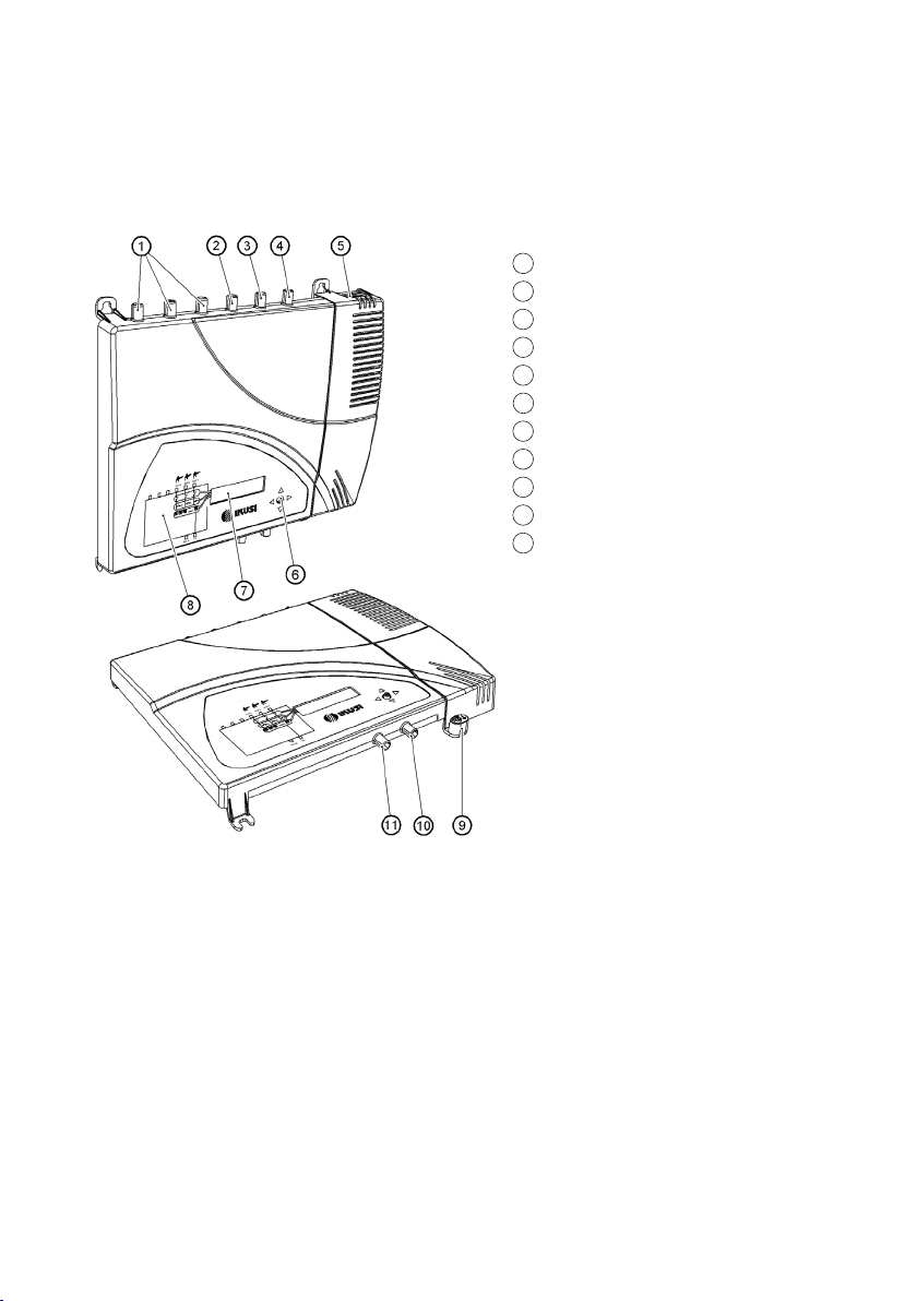
KEY
1 Unavailable inputs
2 UHF3 input
3 UHF2 input
4 UHF1 input
5 Mains connector
6 Control button
7 Screen (LCD)
8 Front panel with cluster map
9 Earthing
10 TV outlet
11 Cloning connector
Introduction/General use of the unit
7
FReprogrammable as many times as required.
J10 tuneable UHF lters that can each process between 1 and 5 channels.
JSignal processing:
FUHF inputs with low noise gure (< 6 dB).
FAutomatic signal level equalisation.
FAutomatic gain control.
JExtra functions:
FInternal conguration cloning with transferral between units.
FUnit locking by security code.
JDimensions: 300 mm x 250 mm x 41 mm
JWeight: 2.2 kg
General use of the unit
Interaction with the unit using the control button and how to interpret the instructions
displayed on the LCD screen are described below. The programme includes a main menu
formed by submenus that can be selected to modify the unit operating settings.
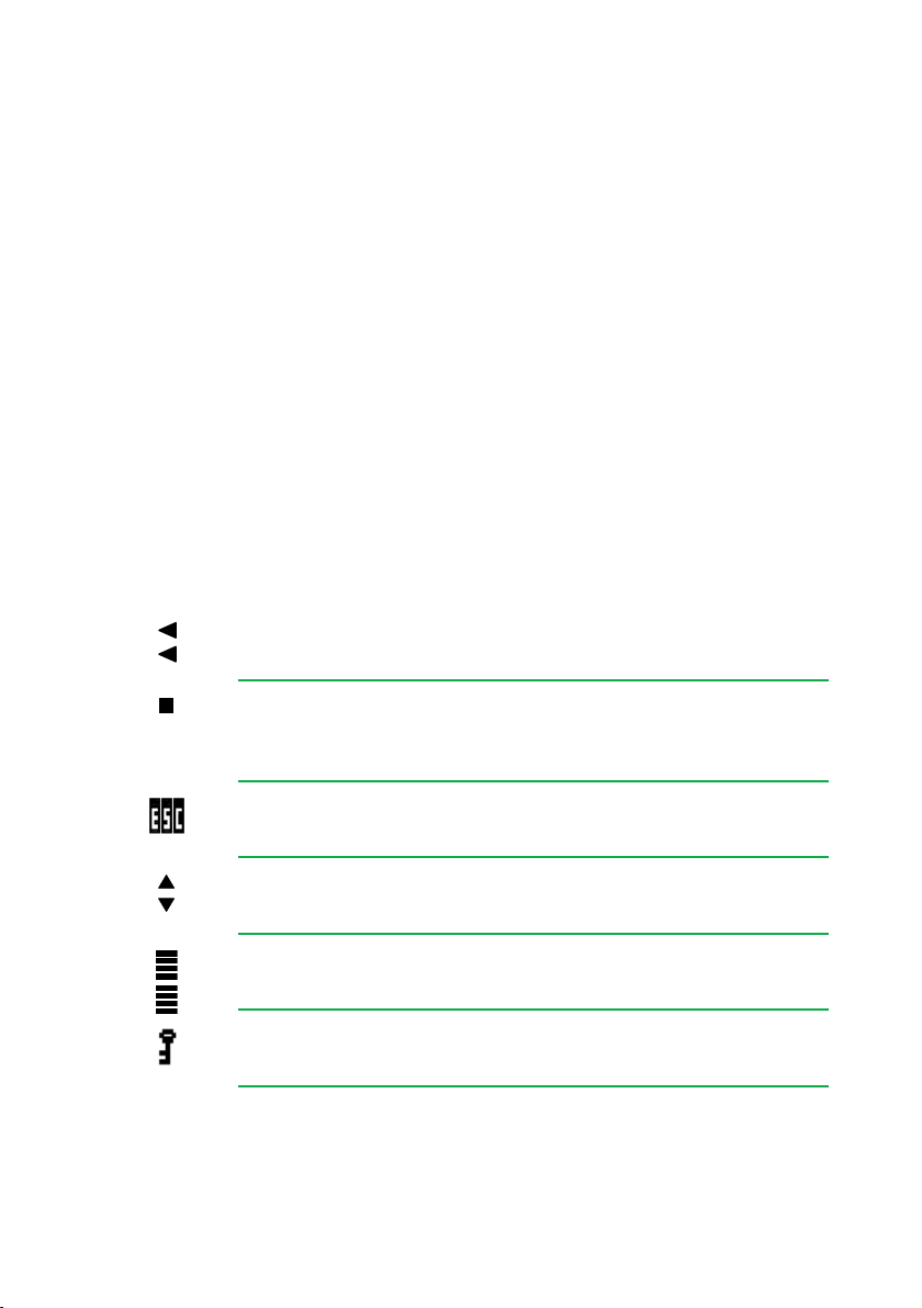
Instructions displayed on the LCD screen
This symbol is displayed when manual setting is selected. It refers to the
clusters indicated on the panel.
This symbol is displayed in the manual setting menu. Visually locate it on
the LCD screen and see the cluster map on the panel to see which of the
3 unit clusters is selected.
This acronym appears on the main menu. Select it to return to the lan-
guage selection menu.
This symbol is displayed in manual settings and advanced settings and
visually indicates the possibility of moving vertically.
This symbol is displayed in manual and advanced settings and always
includes a numeric value and visually indicates the gain level.
This icon is displayed with the unit lock enabled when the unit is
switched on and after periods when the unit is not in use.
EN
Introduction/General use of the unit
8
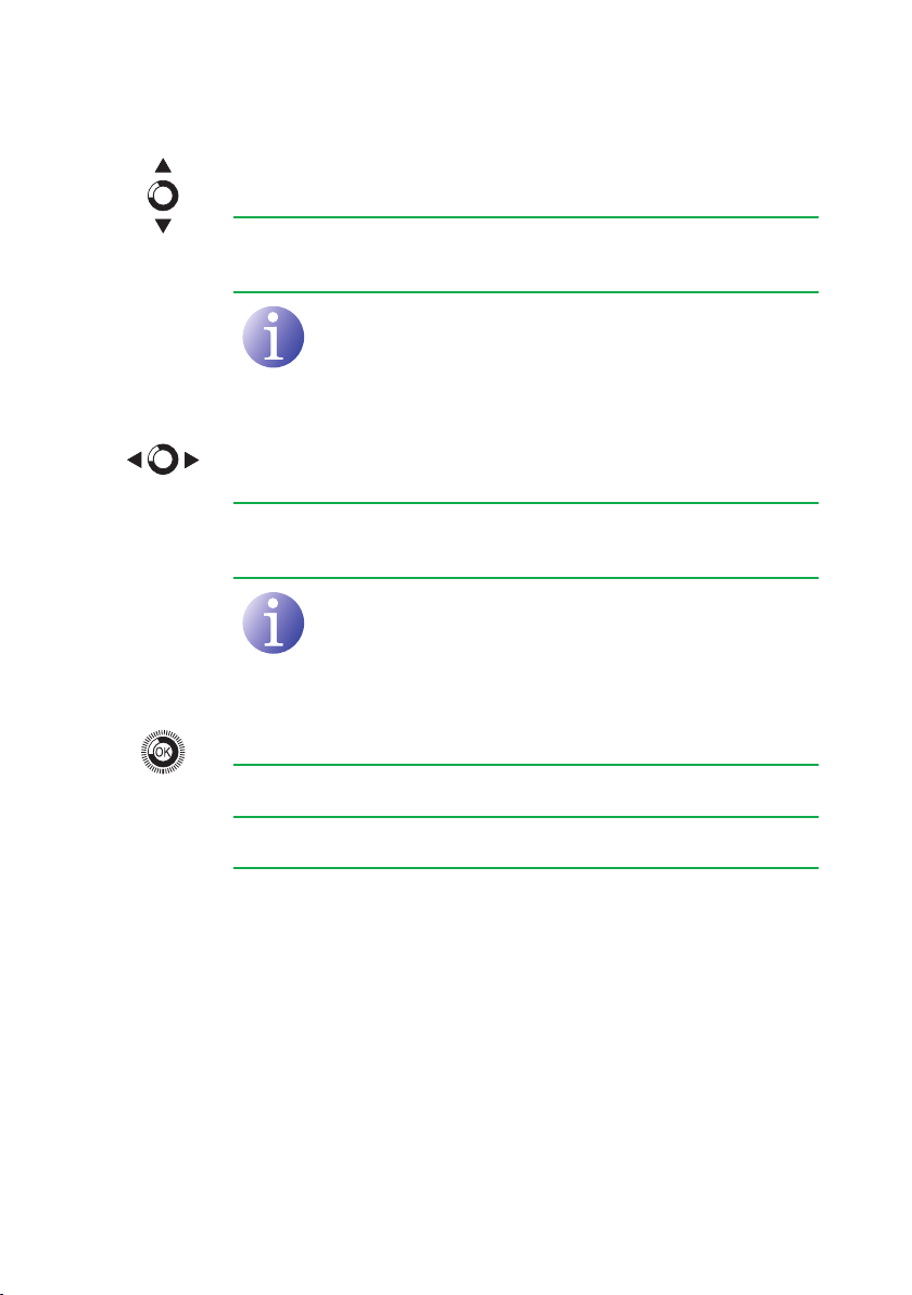
Vertical button movement
In the menus and submenus, move the button up or down to browse
upwards and downwards position by position.
In the settings, move the button up or down to modify values position by
position.
NOTE
Keep the button pressed up or down to browse or to modify
values more quickly.
Horizontal button movement
In the menus, move the button to the left or the right to select and go
back position by position.
In the settings, move the button to the left or the right to select and go
back position by position.
NOTE
Keep the button pressed to the left or to the right to browse
more quickly.
Press button
In the menus, this selects the submenu.
In the submenus, this selects the setting.
In the settings, this selects the parameter value.

9
Unit installation and configuration
Only the LCD screen and the control button are required to congure the unit. Follow the
steps below to install the unit and congure the different parameters.
Installation
RISK OF DAMAGE TO THE UNIT
Mechanical handling of the unit while
it is switched on may lead to it being
damaged. Do not plug the unit into the
mains before or during installation.
1) Fit and tighten the bolts and plugs securing
the unit to the wall.
2) Connect the coaxial cable from the aerial to
the unit.
3) Connect the coaxial cable from the outlet to
the unit.
Power connection
DANGER OF DEATH OR INJURY
Incorrect unit power connection may
cause an electric shock. Follow the
steps below for the electrical installation
of the unit.
1) Connect the earthing cable.
2) Connect the power plug to the unit mains
connector.
3) Connect the power plug to the mains socket.
ATTENTION
DANGER
EN
Unit installation and configuration/Fast menu guide
10
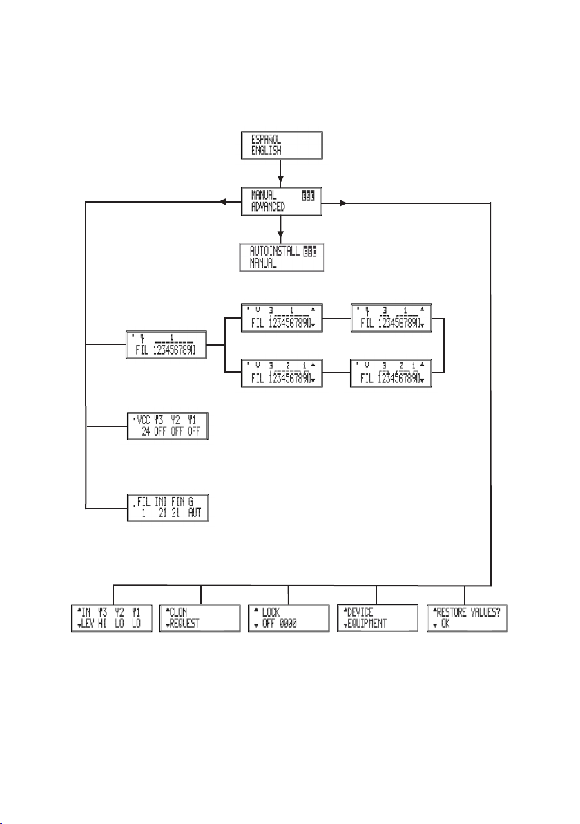
Fast menu guide
Language
selection
(10-0-0)
(7-0-3)
Filter allocation
to aerials
(9-0-1)
(2-5-3)
(2-7-1)
Mast-head amplier power supply
Aerial lter setting
Self-installation
Input preamps Conguration
cloning
Lock Unit
information
Restore set-
tings
Manual setting Advanced settings
This manual suits for next models
1
Table of contents
Other IKUSI Amplifier manuals

IKUSI
IKUSI SBA190 Series User manual

IKUSI
IKUSI One Sat 118 User manual

IKUSI
IKUSI SRF Series User manual

IKUSI
IKUSI ONE SAT User manual

IKUSI
IKUSI ATP-900 User manual

IKUSI
IKUSI ONE+ SAT User manual

IKUSI
IKUSI ONE Series User manual

IKUSI
IKUSI MB-01 User manual

IKUSI
IKUSI NBS-200 User manual

IKUSI
IKUSI NBS-200 Series User manual

IKUSI
IKUSI One Sat 123 User manual

IKUSI
IKUSI NBS-600 Series User manual

IKUSI
IKUSI ONE Compact User instructions

IKUSI
IKUSI NBS-801-C48 User manual

IKUSI
IKUSI NBS-600 Series User manual

IKUSI
IKUSI NBS-800 Series User manual

IKUSI
IKUSI 2844 User manual

IKUSI
IKUSI NBS-800 Series User manual

IKUSI
IKUSI ONE SAT User manual

IKUSI
IKUSI SBA-103-C60 User manual


