manuals.online logo
Brands
  1. Home
  2. •
  3. Brands
  4. •
  5. iNels
  6. •
  7. Controllers
  8. •
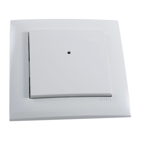
  9. iNels RFWB-20/G User manual

iNels RFWB-20/G User manual

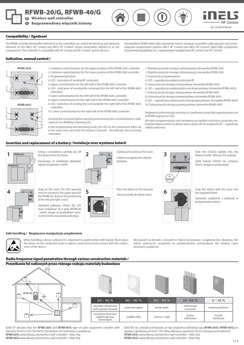
RFWB-20/G, RFWB-40/G
Wireless wall controller
EN
02-13/2019 Rev.0
1 / 2
Indication, manual control /
1. Common control buttons for the upper position of the RFWB-20/G controller
2. Common control buttons for the lower position of the RFWB-20/G controller
3. Programming button
4. LED - indication of sending RF command
5. Upper control button for the left half of the RFWB-40/G controller
6. LED - indication of sending the command (for the left half of the RFWB-40/G
controller)
7. Lower control button for the left half of the RFWB-40/G controller
8. Upper control button for the right half of the RFWB-40/G controller
9. LED - indication of sending the command (for the right half of the RFWB-40/G
controller)
10. Lower control button for the right half of the RFWB-40/G controller
Sending the command (when pressing and releasing the control button) is indi-
cated on the RFWB by a flashing LED.
In the programming and operating mode, the LED on the component lights up
at the same time each time the button is pressed - this indicates the incoming
command.
1.
2.
3.
4.
RFWB-20/G
5.
7.
3.
9.
6.
8.
10.
RFWB-40/G
Compatibility /
4 5 6
3
+
CR2032
When handling a device unboxed it is important to avoid contact with liquids. Never place
the device on the conductive pads or objects, avoid unnecessary contact with the compo-
nents of the device.
Insertion and replacement of a battery /
Safe handling /
21 RFWB-20/G
RFWB-40/G
Using a screwdriver, carefully pry off
the device from the frame.
Gently pull to remove the cover. Slide the CR2032 battery into the
battery holder. Observe the polarity.
Place the frame on the rear part. Snap the device with the cover into
the prepared frame.
Snap on the cover. The LED opening
must be located in the upper part (for
the RFWB-40, observe the positioning
of the left and right cover).
The RFWB controller (hereinafter referred to as the controller) can control all switching and dimming
elements of the iNELS RF Control and iNELS RF Control2system (hereinafter referred to as the
components). The controller is compatible with RF Control and RF Control2system devices.
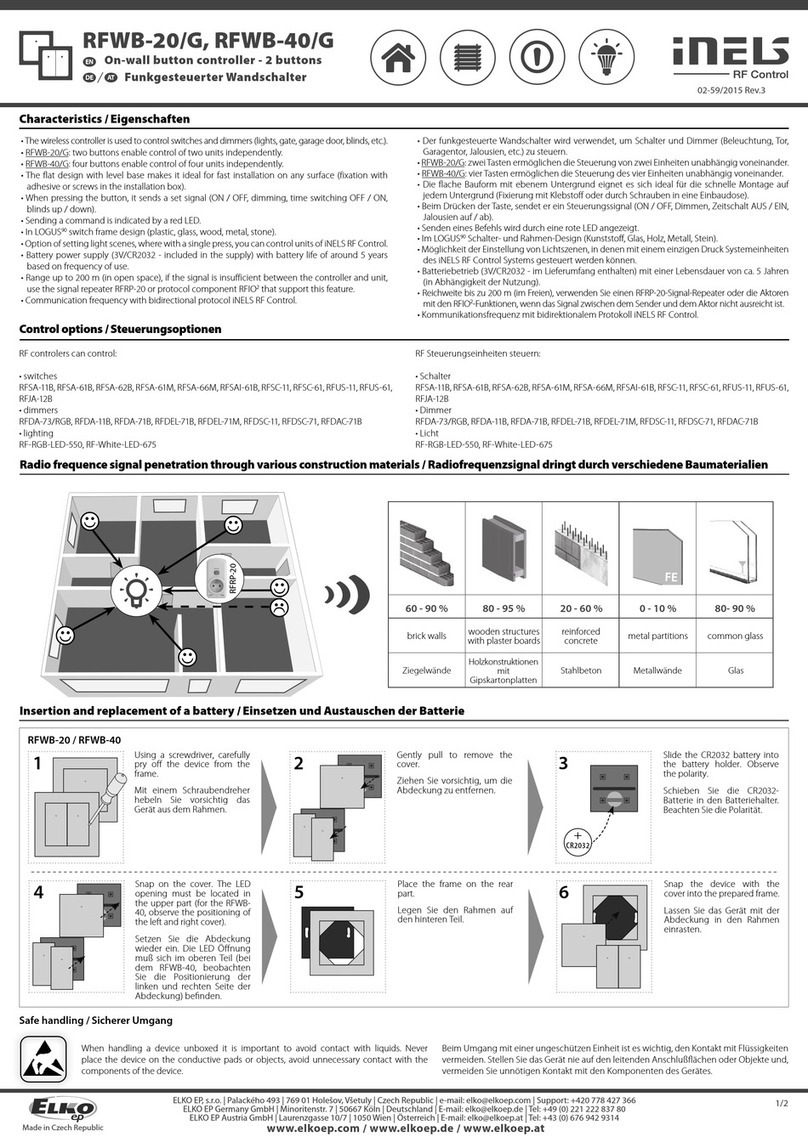
Radio frequence signal penetration through various construction materials /
80 - 95 % 80 - 90 % 60 - 90 % 20- 60 % 0 - 10 %
wooden structures
with plaster boards common glass brick walls reinforced
concrete metal partitions
ELKO EP declares that the RFWB-20/G and RFWB-40/G type of radio equipment complies with
Directive 2014/53 / EU. The full EU Declaration of Conformity is available at:
RFWB-20/G: www.elkoep.com/wireless-wall-controller---rfwb-20g
RFWB-40/G: www.elkoep.com/wireless-wall-controller---rfwb-40g
x
RFRP-20
Nástěnný bezdrátový ovladač
CZ
Indikace, manuální ovládání
1. Společná ovládací tlačítka pro horní pozici ovladače RFWB-20/G
2. Společná ovládací tlačítka pro dolní pozici ovladače RFWB-20/G
3. Programovací tlačítko
4. LED - indikace odesílání RF povelu
5. Horní ovládací tlačítko pro levou polovinu ovladače RFWB-40/G
6. LED - indikace odesílání povelu (pro levou polovinu ovladače RFWB-40/G)
7. Dolní ovládací tlačítko pro levou polovinu ovladače RFWB-40/G
8. Horní ovládací tlačítko pro pravou polovinu ovladače RFWB-40/G
9. LED - indikace odesílání povelu (pro pravou polovinu ovladače RFWB-40/G)
10. Dolní ovládací tlačítko pro pravou polovinu ovladače RFWB-40/G
Odeslání povelu (při stisku i uvolnění ovládacího tlačítka) je na RFWB indikováno
probliknutím LED.
V programovacím a mazacím režimu při každém stisku tlačítka ovladače součas-
ně dlouze zasvítí LED na RF prvku - indikuje tím příjem povelu.
Kompatibilita
Při manipulaci s přístrojem bez krabičky je důležité zabránit kontaktu s tekutinami. Přístroj
nikdy nepokládejte na el. vodivé podložky a předměty, nedotýkejte se zbytečně součástek
na přístroji.
Vložení a výměna baterie
Bezpečná manipulace s přístrojem
Pomocí šroubováku opatrně vycvak-
něte přístroj z rámečku.
Lehkým tahem sundejte kryt.
Baterii CR2032 zasuňte do držáku ba-
terie. Pozor na polaritu.
Nacvakněte kryt. Otvor pro LED musí
být umístěn v horní části (u RFWB-40
pozor na umístění levého a pravého
krytu).
Rámeček umístěte na zadní díl.
Přístroj s krytem nacvakněte do při-
praveného rámečku.
Ovladačem RFWB (dále jen ovladač) lze ovládat všechny spínací a stmívací prvky systému iNELS RF
Control a iNELS RF Control2(dále jen prvky). Ovladač je kompatibilní se systémovými prvky RF Control
a RF Control2.
Prostup radiofrekvenčních signálů různými stavebními materiály
cihlové zdi
dřevěné konstrukce
se sádrokart.
deskami vyztužený beton kovové přepážkyběžné sklo
Tímto ELKO EP, s.r.o prohlašuje, že typ rádiového zařízení RFWB-20/G a RFWB-40/G je v souladu se směrnicí
2014/53/EU. Úplné znění EU prohlášení o shodě je k dispozici na těchto internetových stránkách:
RFWB-20/G: www.elkoep.cz/nastenny-bezdratovy-ovladac---2-tlacitka---rfwb-20g
RFWB-40/G: www.elkoep.cz/ovladac-rfwb-40g
Made in Czech Republic
Programming /
Snap the device with the cover into
the prepared frame.
2 3
PROG > 1s
1 x
4


5
PROG < 1s
1 x
1RFWB-20/G
RFWB-40/G
6 7 8
xxxxxx
Assignment of system components /
address / The address on the back of the controller is used for assignment to the system
components.
Press of programming button on ac-
tuator for 1 second will activate actua-
tor RF into programming mode. LED
is flashing in 1s interval.
Gently pull to remove the cover.Using a screwdriver, carefully pry off
the device from the frame.
Press of programming button on
actuator shorter then 1 second will
finish programming mode.
Snap on the cover. The LED opening
must be located in the upper part (for
the RFWB-40, observe the positioning
of the left and right cover).
Hold the programming button on the RFWB. Press the selected control button on the RFWB according
to the desired function (for more information on individual functions and programming, see the manual
of the specific component). There must be a lapse of 1 second between individual presses. Then release
the programming button.
Place the frame on the rear part.
RFWB-20/G RFWB-40/G
Supply voltage:
Transmission indication:
Number of control buttons:
Programming button:
Transmitter frequency:
Signal transmission method:
Range in free space:
Other data
Operating temperature:
Operating position:
Mounting:
Protection:
Contamination degree:
Dimensions:
LOGUS90 frame - plastic:
LOGUS90 frame
- metal, glass, wood, granite:
Weight:
Related standards:
Technical parameters /
* Comes with plastic frame, without battery.
Attention:
No installation into multi-frames.
When you instal iNELS RF Control system, you have to keep
minimal distance 1 cm between each units.
Between the individual commands must be an interval of
at least 1s.
Instruction manual is designated for mounting and also for user of the device. It is
always a part of its packing. Installation and connection can be carried out only by a
person with adequate professional qualification upon understanding this instruction
manual and functions of the device, and while observing all valid regulations. Trouble-
free function of the device also depends on transportation, storing and handling. In
case you notice any sign of damage, deformation, malfunction or missing part, do
not install this device and return it to its seller. It is necessary to treat this product and
its parts as electronic waste after its lifetime is terminated. Before starting installa-
tion, make sure that all wires, connected parts or terminals are de-energized. While
mounting and servicing observe safety regulations, norms, directives and professional,
and export regulations for working with electrical devices. Do not touch parts of the
device that are energized – life threat. Due to transmissivity of RF signal, observe cor-
rect location of RF components in a building where the installation is taking place.
RF Control is designated only for mounting in interiors. Devices are not designated
for installation into exteriors and humid spaces. The must not be installed into metal
switchboards and into plastic switchboards with metal door – transmissivity of RF
signal is then impossible. RF Control is not recommended for pulleys etc. – radiofre-
quency signal can be shielded by an obstruction, interfered, battery of the transceiver
can get flat etc. and thus disable remote control.
The company ELKO EP, as the manufacturer, is entitled to make technical modificati-
ons to the product, in the technical specification and product manual, without prior
notification.
Warning /
ELKO EP, s.r.o. | Palackého 493 | 769 01 Holešov, Všetuly | Česká republika | e-mail: [email protected]
EN Support: +420 778 427 366 | CZ Technická podpora: +420 775 444 609
www.elkoep.com
Programování
Přiřazení k systémovým prvkům
adresa
Pro přiřazení k systémovým prvkům slouží adresa, uvedená na zadní straně
ovladače.
Na RFWB přidržte programovací tlačítko. Zvolené ovládací tlačítko na RFWB stiskněte dle požadované
funkce (podrobnější informace k jednotlivým funkcím a programování naleznete v návodu konkrétního
prvku). Mezi jednotlivými stisky musí být prodleva 1 vteřina. Poté programovací tlačítko uvolněte.
Stiskem programovacího tlačítka na
prvku RF na dobu delší než 1 vteřina
se prvek uvede do programovacího
režimu. LED začne blikat v intervalu
1 vteřiny.
Stiskem programovacího tlačítka na
prvku RF na dobu kratší než 1 vteřina
se ukončí programovací režim.
Napájecí napětí:
Indikace přenosu:
Počet ovládacích tlačítek:
Programovací tlačítko:
Frekvence:
Způsob přenosu signálu:
Dosah na volném prostranství:
Další údaje
Pracovní teplota:
Pracovní poloha:
Upevnění:
Krytí:
Stupeň znečištění:
Rozměry:
LOGUS90 rámeček - plast:
LOGUS90 rámeček
- kov, sklo, dřevo, žula:
Hmotnost:
Související normy:
3 Vbattery / baterie CR 2032
red / červená LED
2 4
1
866 MHz, 868 MHz, 916 MHz
unidirectionally addressed message / jednosměrně adresovaná zpráva
up to / až 200 m
-10 ... +50 °C
any / libovolná
glue, screws / lepením, šroubováním
IP20
2
85 x 85 x 16 mm
94 x 94 x 16 mm
55 g* 55 g*
EN 60669, EN 300220, EN 301489 R&TTE Directive, Order. No 426/2000 Coll.
(Directive 1999/EC) / EN 60669, EN 300 220, EN 301 489 směrnice RTTE,
NVč.426/2000Sb (směrnice 1999/ES)
Technické parametry
* Se standardně dodávaným plastovým rámečkem, bez
baterie.
Upozornění:
Neinstalujte do vícerámečků.
Při instalaci systému iNELS RF Control musí být dodržená
minimální vzdálenost mezi jednotlivými prvky 1 cm.
Mezi jednotlivými povely musí být rozestup minimálně 1s.
Návod na použití je určen pro montáž a pro uživatele zařízení. Návod je vždy součástí
balení. Instalaci a připojení mohou provádět pouze pracovníci s příslušnou odbor-
nou kvalifikací, při dodržení všech platných předpisů, kteří se dokonale seznámili
s tímto návodem a funkcí prvku. Bezproblémová funkce prvku je také závislá na
předchozím způsobu transportu, skladování a zacházení. Pokud objevíte jakékoliv
známky poškození, deformace, nefunkčnosti nebo chybějící díl tento prvek neinstalu-
jte a reklamujte jej u prodejce. S prvkem či jeho částmi se musí po ukončení životnosti
zacházet jako s elektronickým odpadem. Před zahájením instalace se ujistěte, že
všechny vodiče, připojené díly či svorky jsou bez napětí. Při montáži a údržbě je nutné
dodržovat bezpečnostní předpisy, normy, směrnice a odborná ustanovení pro práci s
elektrickými zařízeními. Nedotýkejte se částí prvku, které jsou pod napětím - nebezpečí
ohrožení života. Z důvodu prostupnosti RF signálu dbejte na správné umístění RF
prvků v budově, kde se bude instalace provádět. RF Control je určen pouze pro montáž
do vnitřních prostor. Prvky nejsou určeny pro instalaci do venkovních a vlhkých pros-
tor, nesmí být instalovány do kovových rozvaděčů a do plastových rozvaděčů s ko-
vovými dveřmi - znemožní se tím prostupnost radiofrekvenčního signálu. RF Control
se nedoporučuje pro ovládání přístrojů zajišťujících životní funkce nebo pro ovládání
rizikových zařízení jako jsou např. čerpadla, el. topidla bez termostatu, výtahy, klad-
kostroje ap. - radiofrekvenční přenos může být zastíněn překážkou, rušen, baterie
vysílače může být vybita ap. a tím může být dálkové ovládání znemožněno.
Firma ELKO EP jakožto výrobce má právo provádět technické změny na výrobku, v
technické specifikaci a manuálu k výrobku bez předchozího upozornění.
Varování
Pomocí šroubováku opatrně vycvak-
něte přístroj z rámečku.
Lehkým tahem sundejte kryt.
Nacvakněte kryt. Otvor pro LED musí
být umístěn v horní části (u RFWB-40
pozor na umístění levého a pravého
krytu).
Rámeček umístěte na zadní díl.
Přístroj s krytem nacvakněte do při-
praveného rámečku.

This manual suits for next models

1

Other iNels Controllers manuals

iNels RF KEY-40 User manual

iNels

iNels RF KEY-40 User manual

iNels RF KEY User manual

iNels

iNels RF KEY User manual

iNels SA2-04M Simple manual

iNels

iNels SA2-04M Simple manual

iNels KEY2-01 Simple manual

iNels

iNels KEY2-01 Simple manual

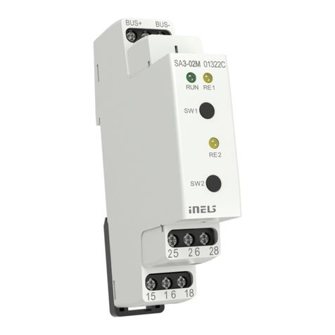
iNels SA3-02M User manual

iNels

iNels SA3-02M User manual

iNels IDRT3-1 User manual

iNels

iNels IDRT3-1 User manual

iNels JA3-018M User manual

iNels

iNels JA3-018M User manual

iNels RFDW-71 User manual

iNels

iNels RFDW-71 User manual

iNels RFWB-20/G User manual

iNels

iNels RFWB-20/G User manual

iNels MI2-02M Simple manual

iNels

iNels MI2-02M Simple manual

iNels JA3-014M User manual

iNels

iNels JA3-014M User manual

iNels RFWB-20/G User manual

iNels

iNels RFWB-20/G User manual

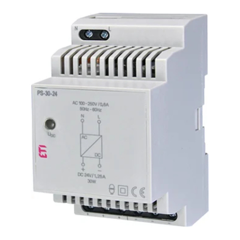
iNels PS-30/24 Quick guide

iNels

iNels PS-30/24 Quick guide

iNels RFOWB-20 User manual

iNels

iNels RFOWB-20 User manual

iNels RFWB-20/G User manual

iNels

iNels RFWB-20/G User manual

iNels SA2-02B Simple manual

iNels

iNels SA2-02B Simple manual

iNels GSB3-40 User manual

iNels

iNels GSB3-40 User manual

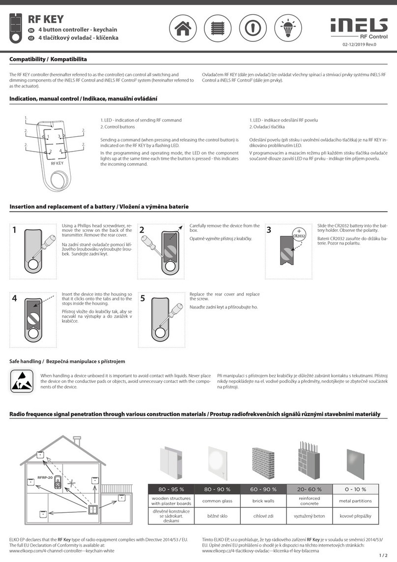
iNels RF KEY User manual

iNels

iNels RF KEY User manual

iNels RFDAC-71B User manual

iNels

iNels RFDAC-71B User manual

iNels SA3-06M User manual

iNels

iNels SA3-06M User manual

iNels JA2-02B User manual

iNels

iNels JA2-02B User manual

iNels RFWB-20/G User manual

iNels

iNels RFWB-20/G User manual

iNels RFWB-20/G User manual

iNels

iNels RFWB-20/G User manual

iNels RFWB-20/G User manual

iNels

iNels RFWB-20/G User manual

Popular Controllers manuals by other brands

BEA MC-Linx Assembly Dimensions

BEA

BEA MC-Linx Assembly Dimensions

Nemtek FG7B Installer manual

Nemtek

Nemtek FG7B Installer manual

Renesas PG-FP5 Setup manual

Renesas

Renesas PG-FP5 Setup manual

Full Gauge Controls MT-512 E 2HP quick start guide

Full Gauge Controls

Full Gauge Controls MT-512 E 2HP quick start guide

socomec ATyS C55 Installation and operating manual

socomec

socomec ATyS C55 Installation and operating manual

Emerson Fincor 2330MKII Series Equipment manual

Emerson

Emerson Fincor 2330MKII Series Equipment manual

Swagelok KCP Series Maintenance instructions

Swagelok

Swagelok KCP Series Maintenance instructions

YASKAWA SGD7S series product manual

YASKAWA

YASKAWA SGD7S series product manual

Eaton Cutler-Hammer Pow-R-Command JCI-100 Installation leaflet

Eaton

Eaton Cutler-Hammer Pow-R-Command JCI-100 Installation leaflet

HomeSeer Technologies HomeTroller Zee quick start guide

HomeSeer Technologies

HomeSeer Technologies HomeTroller Zee quick start guide

Linear Technology DC1814A Demo Manual

Linear Technology

Linear Technology DC1814A Demo Manual

Minarik PCM23001A user manual

Minarik

Minarik PCM23001A user manual

Mitsubishi Electric MELSEC iQ-F Series Quick connection guide

Mitsubishi Electric

Mitsubishi Electric MELSEC iQ-F Series Quick connection guide

Siemens Simatic S7-1500 System manual

Siemens

Siemens Simatic S7-1500 System manual

Orbit Merret OM 402PID manual

Orbit Merret

Orbit Merret OM 402PID manual

SAMES KREMLIN LP 6 - 0.5/4 Translation from the original manual

SAMES KREMLIN

SAMES KREMLIN LP 6 - 0.5/4 Translation from the original manual

Kobold ZOK-E1 Supplementary operating instructions

Kobold

Kobold ZOK-E1 Supplementary operating instructions

Evak DPC-10 Operation manual

Evak

Evak DPC-10 Operation manual

manuals.online logo
manuals.online logoBrands
  • About & Mission
  • Contact us
  • Privacy Policy
  • Terms and Conditions

Copyright 2025 Manuals.Online. All Rights Reserved.