manuals.online logo
Brands
  1. Home
  2. •
  3. Brands
  4. •
  5. iNels
  6. •
  7. Controllers
  8. •
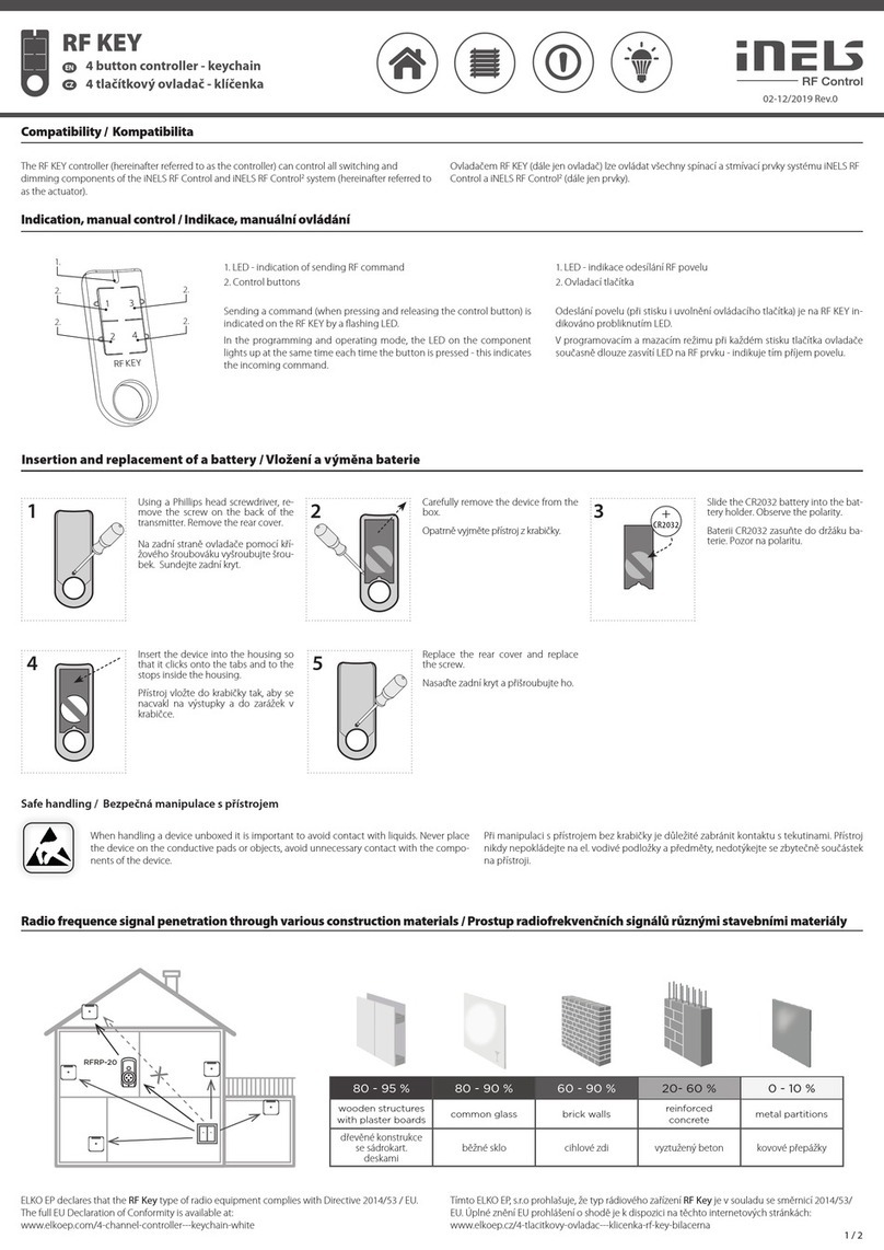
  9. iNels RFSTI-111B User manual

iNels RFSTI-111B User manual

02-216/2016 Rev.0
RFSTI-111B
Overheating protection of room
EN
Made in Czech Republic
Characteristics /
• The component measures temperature in the range of 15...35 °C external sensor and on the basis
of the set temperature switches air conditioning.
• It is particularly suitable for rooms with a tropical climate.
• With the window / door sensor programmed, when the window / door is opened, the device
relay contact is automatically disconnected, thereby saving unnecessary energy consumed for
cooling when the window / door is open.
• The BOX design lets you mount it right in an installation box, a ceiling or controlled appliance
cover.
• It enables connection of the switched load up to 12 A (3000 VA).
• Up to 4 RFDW-100 detectors can be connected to one RFSTI-111B device.
• Range up to 160 m (in open space), if the signal is insufficient between the controller and unit,
use the signal repeater RFRP-20 or protocol component RFIO2that support this feature.
• For components it is possible to set the repeater function via the RFAF/USB service device.
• Communication frequency with protocol iNELS RF Control2(RFIO2).
• External sensor TC (0 ..+70 °C) or TZ (-40 ..+125 °C) for length of 3 m, 6 m, 12 m.
mounting in an installation box
Assembly /
ceiling mounted
Avoid rapid temperature changes, direct sunlight and excessive moisture.
The temperature units should not be located near windows or heating
equipment, etc., which could affect the internal temperature sensor.
°C
Connection /
1 / 3
RFSTI-111B/24V
T T
L
N
12-24 V AC/DC
T T
L
N
RFSTI-111B/230V
RFSTI-111B/120V
Radio frequency signal penetration through various construction materials /
60 - 90 % 80 - 95 % 20 - 60 % 0 - 10 % 80- 90 %
brick walls wooden structures
with plaster boards
reinforced
concrete metal partitions common glass
☺
☺
☺
☺

☺
RFRP-20
For more information, see“Installation manual iNELS RF Control”:
http://www.elkoep.com/catalogs-and-brochures
www.elkoep.com
ELKO EP, s.r.o. | Palackého 493 | 769 01 Holešov, Všetuly | Česká republika | e-mail: [email protected]
EN Support: +420 778 427 366 | CZ Technická podpora: +420 775 444 609
Ochranný teplotní prvek
CZ
Nevystavujte prudkým teplotním změnám, přímému slunečnímu záření
a nadměrné vlhkosti.
Teplotní aktory umístěte tak, aby nebyly v blízkosti
oken nebo topných zařízení apod., která by mohla ovlivňovat interní tep-
lotní senzor.
montáž do instalační krabice
Montáž
montáž do podhledu
Zapojení
• Prvek měří teplotu v rozsahu 15 .. 35 °C externím senzorem a na základě nastavené teploty spíná
klimatizaci.
• Je vhodný zejména pro hotelové pokoje.
• Při zaučení okenního / dveřního senzoru dojde při otevření okna / dveří k automatickému roz-
pojení kontaktu relé zařízení, tak šetří zbytečně vynaloženou energii pro chlazení při otevřeném
okně / dveřích.
• Provedení BOX nabízí montáž do instalační krabice, podhledu nebo krytu ovládaného spotřebiče.
• Umožňuje připojení spínané zátěže do 12 A (3 000 VA).
• K jednomu prvku RFSTI-111B lze připojit max. 4 detektory RFDW-100.
• Dosah 160 m (volné prostranství), v případě nedostatečného signálu mezi ovladačem a prvkem
použijte opakovač signálu RFRP-20 nebo prvky s protokolem RFIO2, které tuto funkci podporují.
• U prvků lze nastavit funkci opakovače (repeatru) prostřednictvím servisního zařízení RFAF/USB.
• Komunikace s protokolem iNELS RF Control2(RFIO2).
• Externí sensor TC (0 ..+70 °C) nebo TZ (-40 ..+125 °C) o délce 3 m, 6 m, 12 m.
Charakteristika
Prostup radiofrekvenčních signálů různými stavebními materiály
cihlové zdi
dřevěné konstrukce
se sádrokart.
deskami
vyztužený beton kovové přepážky běžné sklo
Podrobnější informace naleznete v Instalačním manuálu iNELS RF Control:
https://www.elkoep.cz/katalogy
02-216/2016 Rev.0
RFSTI-111B
Overheating protection of room
EN
Made in Czech Republic
Indication, manual control /
LED REG
terminal board /
hysteresis /
temperature /
LED STATUS
• HYST - setting hysteresis in range 0.5-5°C.
• TEMP - setting temperature in range 15-35°C.
• Terminal board - connection for an external temperature sensor.
• Green LED REG - indication regulation.
• LED STATUS - relay switching indication.
• Programming is performed by pressing the PROG button for more
than 1s.
In programming and delete mode, each time the detector is pro-
grammed, the LED on the device lights up for a single long flash - this
indicates the incoming command.
button /
2 / 3
ON
1 2
Delete one detector from memory /
Delete actuator /
Deleting the entire memory /
PROG > 5s
1 x PROG > 8s
1 x
Pull the battery out of the detector. By pressing the programming
button on the actuator for 5 seconds, deletion of one detector
activates. The LED flashes in an interval of 1s.
Inserting the battery into the detector will send a signal to
delete the device memory.
The LED goes out and the actuator returns to operating mode.
Functions and programming /
While holding the tamper,
insert the battery into the de-
tector (see detector manual).
Tamper Hold Min. 1s after in-
serting the battery. The detec-
tor is then stored in the RFSTI-
111B memory.
Press of programming but-
ton on receiver RFSTI-111B
shorter then 1 second will fin-
ish programming mode, LED
switches off.
Press of programming but-
ton on receiver RFSTI-111B for
1second will activate receiver
RFSTI-111B into programming
mode. LED is flashing in 1s
interval.
Programming /
The external sensor senses the temperature of the room, turns the air conditioner on and
off according to the set temperature. Responds to commands from the detector - when you
open the window, turn off air conditioning.
2
PROG > 1s
1 x
4
PROG >1s
1 x
Description of function /
3RFWD-100
ON
1 2
+
CR2032
ON
1 2
1Set the DIP-1 to the OFF posi-
tion on the detector and set
the DIP-2 to the ON position.
RFWD-100

By pressing the programming button on the actuator for 8 sec-
onds, deletion occurs of the actuator's entire memory. LED
flashs 4x in each 1s interval.
The actuator goes into the programming mode, the LED flashes
in 0.5s intervals (max. 4 min.).
You can return to the operating mode by pressing the Prog but-
ton for less than 1s.
www.elkoep.com
ELKO EP, s.r.o. | Palackého 493 | 769 01 Holešov, Všetuly | Česká republika | e-mail: [email protected]
EN Support: +420 778 427 366 | CZ Technická podpora: +420 775 444 609
Ochranný teplotní prvek
CZ
Indikace, manuální ovládání
svorkovnice
hystereze
teplota
• Svorkovnice - připojení pro externí teplotní sensor.
• Zelená LED REG - indikace regulace.
• LED STATUS - indikace sepnutí relé.
• Programování se provádí stiskem tlačítka PROG > 1s.
V programovacím a mazacím režimu při každém programování detek-
toru dlouze zasvítí LED na prvku - indikuje tím příjem povelu.
• HYST - nastavení hystereze v rozsahu 0.5-5°C.
• TEMP - nastavení požadované teploty v rozsahu 15-35°C.
tlačítko PRG
Funkce a programování
Externí čidlo snímá teplotu v místnosti a spíná klimatizaci dle nastavené teploty. Reaguje na
povel detektoru - při otevření okna vypne klimatizaci.
Popis funkce
Při stisknutém tamperu vlož-
te baterii do detektoru (viz
manuál detektoru). Tamper
držte minimálně 1s po vložení
baterie. Tím se detektor uloží
do paměti RFSTI-111B.
Stiskem programovacího tla-
čítka na RFSTI-111B na dobu
kratší než 1 vteřina se ukon-
čí programovací režim, LED
zhasne.
Stiskem programovacího tla-
čítka na prvku RFSTI-111B na
dobu 1 vteřiny se uvede prvek
do programovacího režimu.
LED bliká v intervalu 1 vteřiny.
Programování
Vymazání jednoho detektoru z paměti
Mazání prvku
Vymazání celé paměti
Vytáhněte z detektoru baterii. Stiskem programovacího tlačít-
ka na prvku RFSTI-111B na dobu 5-ti vteřin se aktivuje mazání
jednoho detektoru. LED bliká v intervalu 1s. Vložení baterie do
detektoru vyšle signál a tím se z paměti prvku vymaže.
LED zhasne a prvek se vrátí do provozního režimu.
Na detektoru nastavte DIP-1
do pozice OFF, DIP-2 nastavte
do pozice ON.
Stiskem programovacího tlačítka na prvku RFSTI-111B na dobu
8 vteřin se vymaže celá paměť prvku. LED 4x problikne ve vte-
řinovém intervalu.
Prvek přejde do programovacího režimu, LED bliká v 0.5s inter-
valech (max. 4 min.).
Návrat do provozního režimu provedete stiskem Prog tlačítka na
dobu kratší než 1s.
02-216/2016 Rev.0
RFSTI-111B
Overheating protection of room
EN
Made in Czech Republic
Technical parameters /
* Temperature sensor input is at the supply voltage potential.
Attention:
When you instal iNELS RF Control system, you have to keep minimal distance 1 cm between each units.
Between the individual commands must be an interval of at least 1s.
Instruction manual is designated for mounting and also for user of the device. It is always a part of its packing.
Installation and connection can be carried out only by a person with adequate professional qualification upon
understanding this instruction manual and functions of the device, and while observing all valid regulations.
Trouble-free function of the device also depends on transportation, storing and handling. In case you notice any
sign of damage, deformation, malfunction or missing part, do not install this device and return it to its seller. It
is necessary to treat this product and its parts as electronic waste after its lifetime is terminated. Before starting
installation, make sure that all wires, connected parts or terminals are de-energized. While mounting and servicing
observe safety regulations, norms, directives and professional, and export regulations for working with electrical
devices. Do not touch parts of the device that are energized – life threat. Due to transmissivity of RF signal, observe
correct location of RF components in a building where the installation is taking place. RF Control is designated only
for mounting in interiors. Devices are not designated for installation into exteriors and humid spaces. The must not
be installed into metal switchboards and into plastic switchboards with metal door – transmissivity of RF signal is
then impossible. RF Control is not recommended for pulleys etc. – radiofrequency signal can be shielded by an
obstruction, interfered, battery of the transceiver can get flat etc. and thus disable remote control.
Warning
3 / 3
Supply voltage:
Apparent input:
Dissipated power:
Supply voltage tolerance:
Temperature measurement input:
Temp. measurement range and
accuracy:
Output
Number of contacts:
Rated current:
Switching power:
Peak current:
Switching voltage:
Min. switching power:
Insulation voltage between
relay outputs and internal circuits:
Isolates. voltage open relay
contact:
Mechanical service life:
Electrical service life (AC1):
Control
Transmitter frequency:
Range:
Other data
Operating temperature:
Storage temperature:
Indication of relay switch:
Indication regulation:
Operating position:
Mounting:
Protection:
Overvoltage category:
Contamination degree:
Outlets (CY wire, cross-section, length):
Dimensions:
Weight:
www.elkoep.com
ELKO EP, s.r.o. | Palackého 493 | 769 01 Holešov, Všetuly | Česká republika | e-mail: [email protected]
EN Support: +420 778 427 366 | CZ Technická podpora: +420 775 444 609
Ochranný teplotní prvek
CZ
230 V AC / 50-60 Hz 120 V AC / 60 Hz 12-24 V DC / AC 50-60 Hz
9 VA / cos φ = 0.1 9 VA / cos φ = 0.1 -
0.7 W
+10 %; -15 %
1x external TZ/TC temperature sensor input / 1x vstup na externí teplotní senzor TZ/TC*
+15 .. +35 °C; 0.5 °C of the range / z rozsahu
1x switching / spínací (AgSnO2)
12 A / AC1
3000 VA / AC1, 288 W / DC
30 A / max. 4s at / při střídě 10%
250 V AC1 / 24 V DC
100 mA / 10 V
basic insulation (Cat. III surges by EN 60664-1) /
základní izolace (kat. přepětí III dle EN 60664-1)
1 kV
3x10⁷
5x10⁴
866 MHz, 868 MHz, 916 MHz
up to / až 160 m
-15 ... + 50 °C
-30 ... + 70 °C
red / červená LED
green / zelená LED
any / libovolná
free at lead-in wires / volné na přívodních vodičích
IP30
III.
2
2 x 0.75 mm2, 2 x 2.5 mm2, 90 mm
49 x 49 x 21 mm
50 g
Napájecí napětí:
Příkon zdánlivý:
Příkon ztrátový:
Tolerance napájecího napětí:
Vstup pro měření teploty:
Rozsah a přesnost měření teploty:
Výstup
Počet kontaktů:
Jmenovitý proud:
Spínaný výkon:
Špičkový proud:
Spínané napětí:
Min. spínaný proud:
Izolační napětí mezi reléovými
výstupy a vnitřními obvody:
Izolační napětí otevřeného
kontaktu relé:
Mechanická životnost:
Elektrická životnost (AC1):
Ovládání
RF povelem z vysílače:
Dosah:
Další údaje
Pracovní teplota:
Skladovací teplota:
Indikace sepnutí relé:
Indikace regulace:
Pracovní poloha:
Upevnění:
Krytí:
Kategorie přepětí:
Stupeň znečištění:
Vývody (drát CY, průřez, délka):
Rozměr:
Hmotnost:
* Vstup teplotního senzoru je na potenciálu síťového napájecího napětí.
Upozornění:
Při instalaci systému iNELS RF Control musí být dodržená minimální vzdálenost mezi jednotlivými
prvky 1 cm.
Mezi jednotlivými povely musí být rozestup minimálně 1s.
Návod na použití je určen pro montáž a pro uživatele zařízení. Návod je vždy součástí balení. Instalaci a připojení
mohou provádět pouze pracovníci s příslušnou odbornou kvalifikací, při dodržení všech platných předpisů, kteří se
dokonale seznámili s tímto návodem a funkcí přístroje. Bezproblémová funkce přístroje je také závislá na předcho-
zím způsobu transportu, skladování a zacházení. Pokud objevíte jakékoliv známky poškození, deformace, nefunkč-
nosti nebo chybějící díl tento výrobek neinstalujte a reklamujte jej u prodejce. S výrobkem či jeho částmi se musí
po ukončení životnosti zacházet jako s elektronickým odpadem. Před zahájením instalace se ujistěte, že všechny
vodiče, připojené díly či svorky jsou bez napětí. Při montáži a údržbě je nutné dodržovat bezpečnostní předpisy,
normy, směrnice a odborná ustanovení pro práci s elektrickými zařízeními. Nedotýkejte se částí přístrojů, které jsou
pod napětím - nebezpečí ohrožení života. Z důvodu prostupnosti RF signálu dbejte na správné umístění RF kompo-
nentů v budově, kde se bude instalace provádět. RF Control je určen pouze pro montáž do vnitřních prostor. Přístro-
je nejsou určeny pro instalaci do venkovních a vlhkých prostor, nesmí být instalovány do kovových rozvaděčů a do
plastových rozvaděčů s kovovými dveřmi - znemožní se tím prostupnost radiofrekvenčního signálu. RF Control se
nedoporučuje pro ovládání přístrojů zajišťujících životní funkce nebo pro ovládání rizikových zařízení jako jsou např.
čerpadla, el. topidla bez termostatu, výtahy, kladkostroje ap. - radiofrekvenční přenos může být zastíněn překážkou,
rušen, baterie vysílače může být vybita ap. a tím může být dálkové ovládání znemožněno.
Varování
Technické parametry

Other iNels Controllers manuals

iNels RFGB-40 User manual

iNels

iNels RFGB-40 User manual

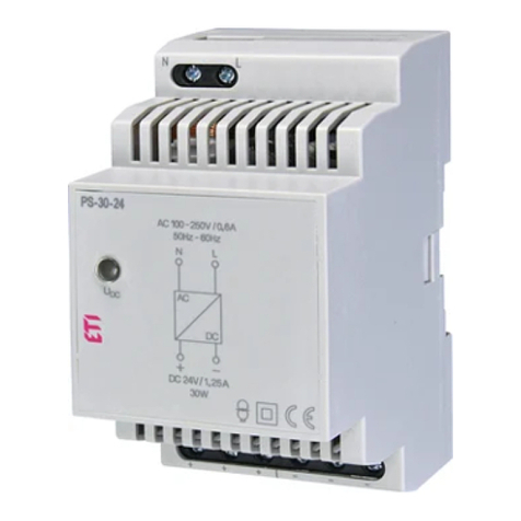
iNels PS-30/24 Quick guide

iNels

iNels PS-30/24 Quick guide

iNels SA2-01B Simple manual

iNels

iNels SA2-01B Simple manual

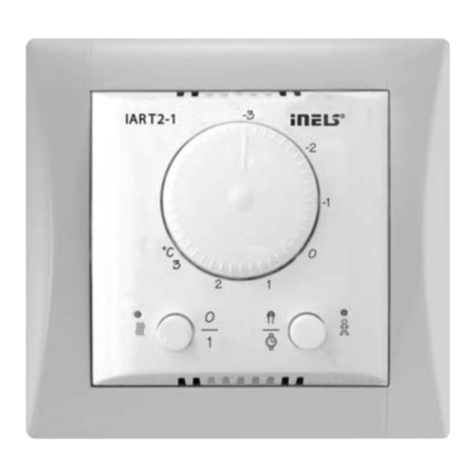
iNels IDRT3-1 User manual

iNels

iNels IDRT3-1 User manual

iNels WTC2-21 Simple manual

iNels

iNels WTC2-21 Simple manual

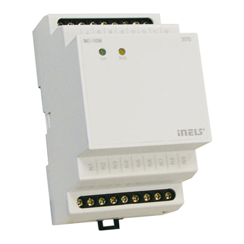
iNels IM2-140M Simple manual

iNels

iNels IM2-140M Simple manual

iNels JA3-014M User manual

iNels

iNels JA3-014M User manual

iNels RFGB-20 User manual

iNels

iNels RFGB-20 User manual

iNels MI2-02M Simple manual

iNels

iNels MI2-02M Simple manual

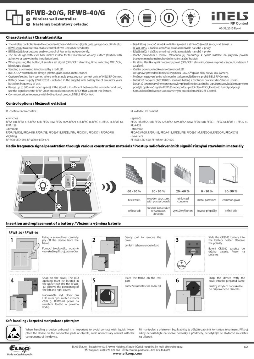
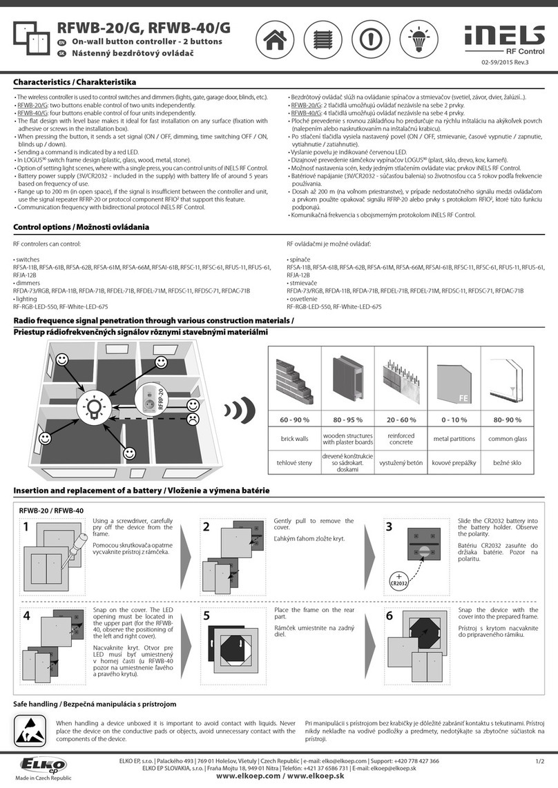
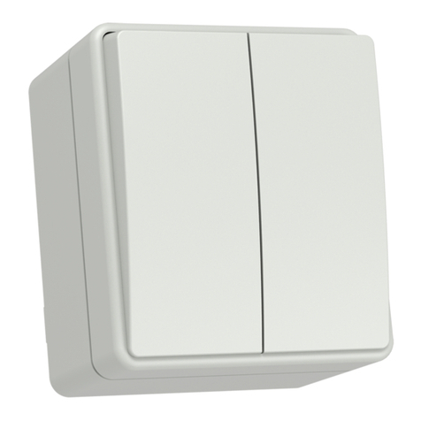
iNels RFWB-20/G User manual

iNels

iNels RFWB-20/G User manual

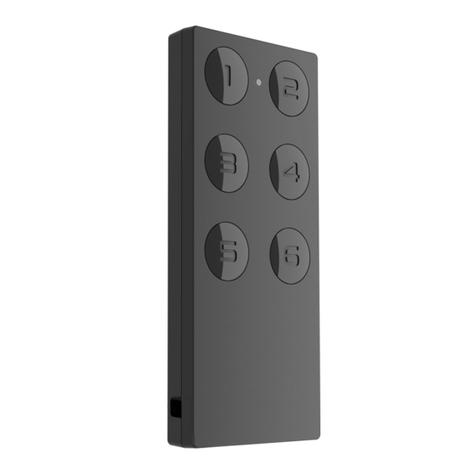
iNels RF KEY User manual

iNels

iNels RF KEY User manual

iNels RF KEY User manual

iNels

iNels RF KEY User manual

iNels RFDA-73M/RGB User manual

iNels

iNels RFDA-73M/RGB User manual

iNels RFDAC-71B User manual

iNels

iNels RFDAC-71B User manual

iNels RFWB-20/G User manual

iNels

iNels RFWB-20/G User manual

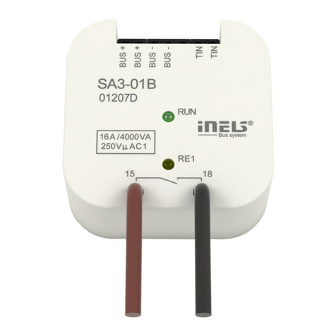
iNels SA3-01B User manual

iNels

iNels SA3-01B User manual

iNels SA3-02M User manual

iNels

iNels SA3-02M User manual

iNels EA3-022M User manual

iNels

iNels EA3-022M User manual

iNels RF KEY-40 User manual

iNels

iNels RF KEY-40 User manual

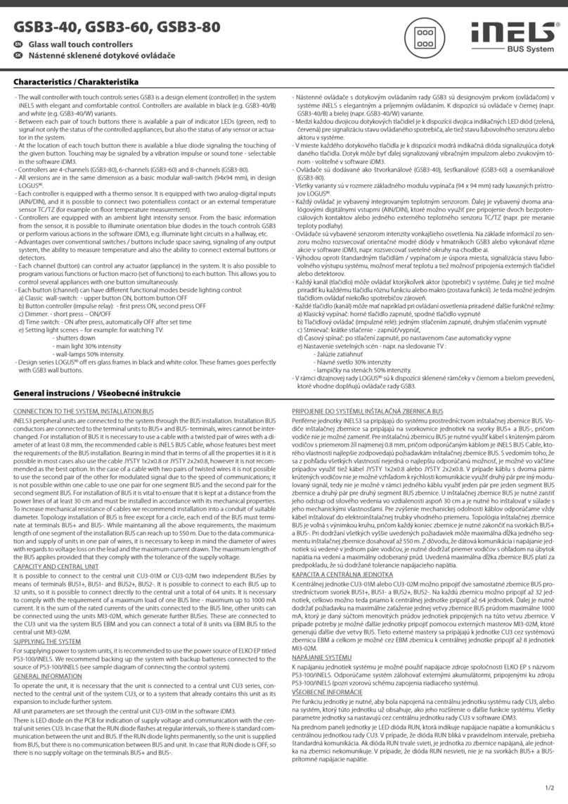
iNels GSB3-40 User manual

iNels

iNels GSB3-40 User manual

iNels RFWB-20/G User manual

iNels

iNels RFWB-20/G User manual

iNels RF KEY - 40 User manual

iNels

iNels RF KEY - 40 User manual

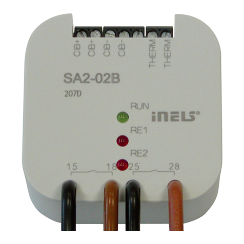
iNels SA2-02B Simple manual

iNels

iNels SA2-02B Simple manual

iNels RFWB-20/G User manual

iNels

iNels RFWB-20/G User manual

Popular Controllers manuals by other brands

SGS electronic TVC-B10 manual

SGS electronic

SGS electronic TVC-B10 manual

White Rodgers 50A62-820 user manual

White Rodgers

White Rodgers 50A62-820 user manual

Texas Instruments DRV2511Q1EVM user guide

Texas Instruments

Texas Instruments DRV2511Q1EVM user guide

Lunatico PocketCW2 user manual

Lunatico

Lunatico PocketCW2 user manual

STMicroelectronics STLUX385A user manual

STMicroelectronics

STMicroelectronics STLUX385A user manual

ABB DCS800-EP Installation and start-up manual

ABB

ABB DCS800-EP Installation and start-up manual

ibis SiViB Record 1500 Installation instructions and operation manual

ibis

ibis SiViB Record 1500 Installation instructions and operation manual

Manitowoc FLOMATIC 464 instructions

Manitowoc

Manitowoc FLOMATIC 464 instructions

GAI-Tronics HUBBCOM GSC1000 Quick installation guide

GAI-Tronics

GAI-Tronics HUBBCOM GSC1000 Quick installation guide

Metso Neles ND9100P Installation maintenance and operating instructions

Metso

Metso Neles ND9100P Installation maintenance and operating instructions

MSD 7730 installation instructions

MSD

MSD 7730 installation instructions

Danfoss AK-CC 250A instructions

Danfoss

Danfoss AK-CC 250A instructions

iSMA iSMA-B-MAC36NL user manual

iSMA

iSMA iSMA-B-MAC36NL user manual

Electrothermal MC227 manual

Electrothermal

Electrothermal MC227 manual

SIIG eSATA II PCIe Pro Quick installation guide

SIIG

SIIG eSATA II PCIe Pro Quick installation guide

Selbit ISP-12F Manual handbook

Selbit

Selbit ISP-12F Manual handbook

Creative Conners Stagehand Mini2 manual

Creative Conners

Creative Conners Stagehand Mini2 manual

Eliwell ID 961 manual

Eliwell

Eliwell ID 961 manual

manuals.online logo
manuals.online logoBrands
  • About & Mission
  • Contact us
  • Privacy Policy
  • Terms and Conditions

Copyright 2025 Manuals.Online. All Rights Reserved.