manuals.online logo
Brands
  1. Home
  2. •
  3. Brands
  4. •
  5. iNels
  6. •
  7. Media Converter
  8. •
  9. iNels ADC3-60M User manual

iNels ADC3-60M User manual

ADC3-60M
02-67/2017 Rev.1
1/2
+
-
BUS
BUS
0(4)-20
mA
0(4)-20
mA 0(1)-10
V
12/24VDC
+
+
++
-
t t
+
-
-
-
-
-
-
1
2
3
4
5
6
7
8
9
++
Analog-digital converter
EN
Characteristics
- ADC3-60M is an analog-to-digital converter and is equipped with 6 analog inputs.
- Analog inputs are used to connect analog sensors that generate a voltage or current signal or
temperature sensors.
- The analog inputs have a resolution of a 14-bit AD converter.
- The analog inputs have a common terminal COM.
- Analog inputs / ouputs are configurable in iDM3 independently as voltage (U) or current (I) or
temperature.
- ADC3-60M is designed to capture as analog voltage signals from a weather station.
- The red LEDs in the front panel indicate exceeding the range, interruption of a sensor or overload
of Uref output.
- The temperature inputs at the top of the terminal are used to connect the following temperature
sensors: - TC, TZ.
- ADC3-60M in 3-MODULE version i s designed for mounting into a switchboard, on a DIN rail
EN60715.
General instrucions
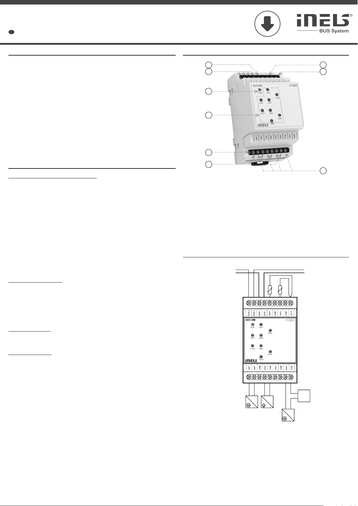
Description of device
Connection
current input without
external power supply
voltage
input
current input with external
power supply
temperature sensors
TC/TZ
1. Analogue output AIN6
2. Data BUS
3. LED indication - state of unit
4. LED indication - state of analogue outputs
5. Reference voltage for sensors Uref1
6. Analogue output AIN1-4
7. Analogue output AIN5
8. Reference voltage for sensors Uref2
9. Terminal for current 0-20 mA measurig by analogue output
CONNECTION TO THE SYSTEM, INSTALLATION BUS
iNELS3 peripheral units are connected to the system through the BUS installation. Installation
BUS conductors are connected to the terminal units to BUS+ and BUS- terminals, wires cannot be
interchanged. For installation of BUS it is necessary to use a cable with a twisted pair of wires with
a diameter of at least 0.8 mm, the recommended cable is iNELS BUS Cable, whose features best
meet the requirements of the BUS installation. Bearing in mind that in terms of all the properties
is it is possible in most cases also use the cable JYSTY 1x2x0.8 or JYSTY 2x2x0.8, however it
is not recommended as the best option. In the case of a cable with two pairs of twisted wires
it is not possible to use the second pair of the other for modulated signal due to the speed of
communications; it is not possible within one cable to use one pair for one segment BUS and the
second pair for the second segment BUS. For installation of BUS it is vital to ensure that it is kept
at a distance from the power lines of at least 30 cm and must be installed in accordance with its
mechanical properties. To increase mechanical resistance of cables we recommend installation
into a conduit of suitable diameter. BUS topology installation is free except for the ring, wherein
each end of the bus must terminate at the terminals BUS + and BUS- peripheral unit. While
maintaining all the above requirements, the maximum length of one segment of the installation
BUS can reach up to 500 m. Due to the data communication and supply of units in one pair of wires,
it is necessary to keep in mind the diameter of wires with regards to voltage loss on the lead and
the maximum current drawn. The maximum length of the BUS applies provided that they comply
with the tolerance of the supply voltage.
CAPACITY AND CENTRAL UNIT
It is possible to connect to the central unit CU3-01M or CU3-02M two independent BUSes by means
of terminals BUS1+, BUS1- and BUS2+, BUS2-. It is possible to connect to each BUS up to 32 units,
so it is possible to connect directly to the central unit a total of 64 units. It is necessary to comply
with the requirement of a maximum load of one BUS line - maximum up to 1000 mA current. When
connecting units which draw greater than 1A, BPS3-01M with 3A sampling can be used. It is the
sum of the rated currents of the units connected to the BUS line, other units can be connected
using the units MI3-02M, which generate further BUSes. These are connected to the CU3 unit via
the system BUS EBM and you can connect a total of 8 units via EBM BUS to the central unit MI3-02M.
SUPPLYING THE SYSTEM
For supplying power to system units, it is recommended to use the power source of ELKO EP titled
PS3-100/iNELS. We recommend backing up the system with backup batteries connected to the
source of PS3-100/iNELS (see sample diagram of connecting the control system).
GENERAL INFORMATION
To operate the unit, it is necessary that the unit is connected to a central unit CU3 series, connected
to the central unit of the system CU3, or to a system that already contains this unit as its expansion
to include further system.
All unit parameters are set through the central unit CU3-01M in the software iDM3.
There is LED diode on the PCB for indication of supply voltage and communication with the
central unit series CU3. In case that the RUN diode flashes at regular intervals, so there is standard
communication between the unit and BUS. If the RUN diode lights permanently, so the unit is
supplied from BUS, but there is no communication between BUS and unit. In case that RUN diode
is OFF, so there is no supply voltage on the terminals BUS+ and BUS-.
Note: Analog output and input of thermo sensor is galvanically connected to BUS.
Made in Czech Republic
ADC3-60M
2/2
ELKO EP, s.r.o. | Palackého 493 | 769 01 Holešov, Všetuly | Czech republic | e-mail: [email protected]
TECHNICAL SUPPORT | E-mail: [email protected] | Mobil: +420 778 427 366 | Tel.: +420 573 514 276, +420 573 514 211 | Fax: +420 573 514 227 | www.inels.com
6x voltage, current or temperature input
6
no
indication (exceeding the range, interruption of a
sensor or overload of Uref output) by the applicable
red LED
COM
14 bits
approx. 150 kΩ
100 Ω
Voltage (U): 0 ÷ +10 V(U); 0 ÷ +2 V(U)
Current (I): 0 ÷ +20 mA (I); 4 ÷ +20 mA (I)
Temperature: input at ext. temperature sensor
TC, TZ see accessories / according to used sensor
from -30°C to 125°C
10 or 15 V DC / 100 mA
10 V DC / 20 mA
BUS
green LED RUN
27 VDC, -20 / +10 %
max. 1 W
100 mA (at 27V DC), from BUS
max. 2.5 mm2 / 1.5 mm2with sleeve
-20 .. +55°C
-30 .. +70°C
IP20 device, IP40 mounting in the switchboard
II.
2
any
into a switchboard rail to DIN EN 60715
3-MODULE
90 x 52 x 65 mm
112 g
Input
Analog inputs:
Number of inputs:
Galv. separation from
inner circuits:
Diagnostic:
Common terminal:
Converter resolution:
Input resistance
- for voltage ranges:
- for current ranges:
Types of inputs /
measuring ranges*:
Outputs of the Uref1 and Uref2 voltage
Voltage** / current of Uref1:
Voltage** / current of Uref2:
Communication
Installation BUS:
Unit status indication:
Power supply
Supply voltage / tolerance:
Dissipated power:
Rated current:
Connection
Terminal:
Operating conditions
Operating temperature:
Storing temperature:
Protection degree:
Overvoltage category:
Pollution degree:
Operating position:
Installation:
Design:
Dimensions and weight
Dimensions:
Weight:
Technical parameters Warning
Before the device is installed and operated, read this instruction manual carefully and with full
understanding and Installation Guide System iNELS3. The instruction manual is designated for
mounting the device and for the user of such device. It has to be attached to electro-installation
documentation. The instruction manual can be also found on a web site www.inels.com. Attention,
danger of injury by electrical current! Mounting and connection can be done only by a professional
with an adequate electrical qualification, and all has to be done while observing valid regulations.
Do not touch parts of the device that are energized. Danger of life-threat! While mounting,
servicing, executing any changes, and repairing it is essential to observe safety regulations, norms,
directives and special regulations for working with electrical equipment. Before you start working
with the device, it is essential to have all wires, connected parts, and terminals de-energized. This
instruction manual contains only general directions which need to be applied in a particular
installation. In the course of inspections and maintenance, always check (while de-energized) if
terminals are tightened.
* Selectable for each input/output individually by configuration in the user program iDM3. Min.
supply voltage 24 V DC must be respected when configuring 15 V DC and 100 mA consumption.
** According to load Uref output.

Other iNels Media Converter manuals

iNels RFSG-1M User manual

iNels

iNels RFSG-1M User manual

iNels Elko AirTM-100S User manual

iNels

iNels Elko AirTM-100S User manual

iNels RFSG-1M User manual

iNels

iNels RFSG-1M User manual

iNels RFSG-1M User manual

iNels

iNels RFSG-1M User manual

iNels Elko AirTM-100L User manual

iNels

iNels Elko AirTM-100L User manual

iNels RFSG-1M User manual

iNels

iNels RFSG-1M User manual

iNels RFSG-1M User manual

iNels

iNels RFSG-1M User manual

iNels DAC3-04B User manual

iNels

iNels DAC3-04B User manual

iNels TI3-60M User manual

iNels

iNels TI3-60M User manual

iNels DAC2-04M User manual

iNels

iNels DAC2-04M User manual

iNels RFSG-1M User manual

iNels

iNels RFSG-1M User manual

iNels ADC3-60M User manual

iNels

iNels ADC3-60M User manual

iNels RFIM-20B User manual

iNels

iNels RFIM-20B User manual

iNels RFTM-1 User manual

iNels

iNels RFTM-1 User manual

iNels RFTM-1 User manual

iNels

iNels RFTM-1 User manual

iNels Elko AirTM-100NB User manual

iNels

iNels Elko AirTM-100NB User manual

Popular Media Converter manuals by other brands

Orei HD-102 user manual

Orei

Orei HD-102 user manual

Manhattan 162579 user manual

Manhattan

Manhattan 162579 user manual

Axis AXIS Q7401 user manual

Axis

Axis AXIS Q7401 user manual

Lehle P-SPLIT STEREO operating instructions

Lehle

Lehle P-SPLIT STEREO operating instructions

Omnitron Systems Technology miConverter 10/100 Specifications

Omnitron Systems Technology

Omnitron Systems Technology miConverter 10/100 Specifications

GMI D6072S-099 instruction manual

GMI

GMI D6072S-099 instruction manual

PCB Piezotronics 422E38 Installation and operating manual

PCB Piezotronics

PCB Piezotronics 422E38 Installation and operating manual

involight DMXS4 user manual

involight

involight DMXS4 user manual

Grundfos CUE quick guide

Grundfos

Grundfos CUE quick guide

Diodes AP63203 user guide

Diodes

Diodes AP63203 user guide

GarrettCom Magnum 14E Installation and user guide

GarrettCom

GarrettCom Magnum 14E Installation and user guide

NAD C 658 Quick setup guide

NAD

NAD C 658 Quick setup guide

Ratoc Systems U2SCXU user guide

Ratoc Systems

Ratoc Systems U2SCXU user guide

Extron electronics DSC 401 user guide

Extron electronics

Extron electronics DSC 401 user guide

LGB 55525 user manual

LGB

LGB 55525 user manual

Avenview HDM-XTRM-IP-SET manual

Avenview

Avenview HDM-XTRM-IP-SET manual

Crystal Vision Indigo Wallbox Q-Down user manual

Crystal Vision

Crystal Vision Indigo Wallbox Q-Down user manual

Monoprice 11751 user manual

Monoprice

Monoprice 11751 user manual

manuals.online logo
manuals.online logoBrands
  • About & Mission
  • Contact us
  • Privacy Policy
  • Terms and Conditions

Copyright 2025 Manuals.Online. All Rights Reserved.