47156310_ed2 5
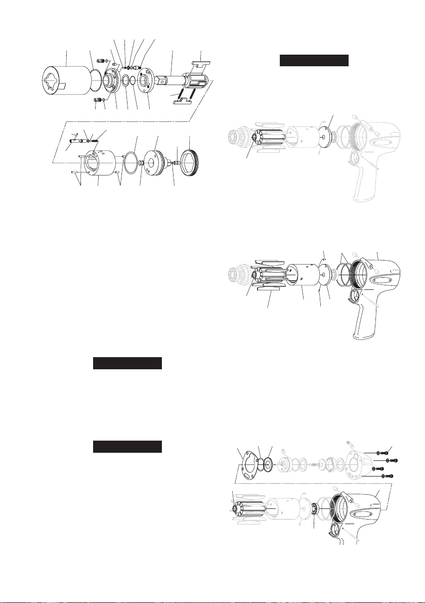
Assembly of Impulse Unit
7374
75
6872 71
69 67
70
66
76 78 77
79
65 80 81
64
82
92 84 94 93 8391
85
90 89 88 87 86
1. Check whether the relief valve move smoothly and install the
O-ring (76) to the Relief Valve (75).
2. Install the greased O-ring (71) to the Sensor (70) using Jig E.
3. Apply grease to the Sensor inserting hole of the Liner Upper Plate
(67) and then install the Sensor (70) by pushing it all the way to
Bottom.
4. Install the Spring (89) and the Ball (90) to the Liner Lower Plate (B)
(83) in the order.
5. Install the Back Up Ring (88) and O-ring (87) to the Liner Lower
Plate (B) (84) in the order.
6. Apply impulse unit oil to the O-ring.
7. Install the Adjust Bolt (86) to the Relief Valve (75) and insert it by
pushing while rotating it counter-clock wise direction.
8. Remove the Relief Valve (75). If Relief Valve does not comes off,
Use adjustment bolt with hexagon wrench to remove the Relief
Valve by rotating it in Clock wise direction.
9. Apply impulse unit oil and assemble Backup Ring (94) and O-ring
(93) in order in the Liner Lower Plate (B) (84) As shown in the
figure above.
10. Assemble Liner lower Plate (A) (83) and (B) (84).
11. Apply Impulse unit oil to the Main Shaft (80) and install the Main
Shaft (80) to Liner Lower Plate Assembly by rotating the shaft.
Be Careful not to damage the O-Ring in the Liner Lower Plate.
12. Assemble Blades (81) and Spring (82) to Main Shaft (80) and keep
them intact in their position.
13. Insert the Main Shaft (80) aligning the Blades (81) with the circle
center of the liner (72).
14. Align the Adjustment Bolt (86) with the Relief Valve (75) inserting
part by rotating the Liner Lower Plate.
15. Apply impulse unit oil to the O-ring (76) and insert the Relief
Valve (75) by rotating it.
Be Careful not to damage the O-Ring
16. Tighten the Adjust Bolt (86) while holding the Relief Valve (75).
to the Liner.
17. Align the Slotted hole of the Relief Valve (75) with the Pin hole of
the Liner and insert the pin (79). Loosen the adjustment bolt 180°
to 360° from the minimum position.
18. Insert the Ball (78) and Spring (77) to the Relief Valve (75) in Order.
19. Align the hole of the Liner Upper Plate (67) with hole of the Liner
(72) and assemble the Liner Upper Plate (67).
20. Install O-ring (65) to the Liner Case (64), Apply impulse unit oil to
O-ring (65) and assemble the Unit with the Liner Upper Plate (72).
21. Insert the above assembled parts to the Liner Case (64). Lightly hold
the unit with hands when the parts inside goes over the O-ring.
22. Apply
impulse unit oil to the end section of the Liner Upper Plate
(67).
23. Use Jig H to fix Liner Case
(64)
and tighten Liner Case Cap (66) to
specified torque using Jig A.
QS110P4 & QS120P4 QS140P4 & QS150P6
80±8Nm 90±9Nm
Check Main Shaft and Adjust Bolt rotates smoothly. Loosen the
Adjust Bolt.
Assembly of Motor
Rotor Adjustment
1. Assemble the Upper Plate assembly to the Rotor (38) by hitting
the Upper Plate (33) by about 2 mm. Make sure Rotor (38) rotates
smoothly. Hit the Upper Plate (33) until there is no clearance between
the Upper Plate (33) and the Rotor (38). Adjust the clearance.
Motor Assembly
1. Install Vanes (39) into the Rotor (38).
2. Apply grease on the Cylinder pin (37) hole and install pin (37) in
the Cylinder (36).
3. Align Cylinder pin (37) with pin hole of the Upper plate (33) and
assemble the Cylinder (36).
4. Assemble the Lower Plate assembly.
5. Apply grease on the pin hole of Upper Plate (33) and install the
Pin (35).
6. Install the O-ring (32) into the Motor Case (1) and slightly apply
grease on the O-ring (32).
7. Aligning the Upper Plate Pin (35) insert the Motor assembly into
the Motor Case (1).
Motor Case Cover Assembly
1. Apply grease on the Bearing (34) of the Rotor (38) and mount the
O-ring (54) and upper plate spacer (53) in order.
2. Install the S-Packing (55) and install Motor Case Cover assembly.