INIM Electronics SmartLoop Owner's manual

SmartLoop
Analogue Fire Alarm Control Panel
Programming Manual
GameOver

Programming Manual
2
Copyright
The information contained in this document is the sole property of Inim Electronics s.r.l. No
part may be copied without written authorization from Inim Electronics s.r.l.
All rights reserved.
This Control panel has been designed and developed to the
highest standards of quality and performance implemented by
Inim Electronics.
This control panel must be installed in accordance with the
instructions described in this manual and in compliance with
the laws in force.
All control panels from the SmartLoop series are EN54-2;
EN54-4 compliant.
All control panels from the SmartLoop series, and all
accessory items and special functions have IMQ Sistemi di

Programming Manual
3
Table of contents
Chapter 1 Introduction ........................................................................ 7
1.1 In order to validate the IMQ-SISTEMI DI SICUREZZA certification, and in
compliance with EN54-2 regulations: 7
Chapter 2 General information.............................................................. 8
2.1 Documentation supplied 8
2.2 Manual details 8
2.3 Addressees 8
2.4 About the Software 8
2.5 Intellectual property rights 8
2.6 Conventions 8
Chapter 3 The SmartLoop control panel ................................................10
3.1 The console 10
3.2 The buttons 11
3.3 The LED 11
Chapter 4 How to use the display and keypad........................................14
4.1 Selecting an option 14
4.2 Selecting a loop device 15
4.3 Editing a programming field 15
4.4 Entering numbers in a numerical-programming field 15
4.5 Selecting values in a variable field 15
Chapter 5 How to view events .............................................................16
5.1 Overview 16
Chapter 6 Configuring and programming the control panel ......................17
6.1 From panel 17
6.2 From computer 17
6.3 From remote computer 17
Chapter 7 Initialising the configuration/programming from panel..............18
7.1 Accessing the main menu 18
7.2 Auto configuration of the system 18
7.3 Restoring to factory default settings 21
7.4 Viewing the control panel configuration 22
7.5 Manual configuration 23
Chapter 8 Initializing configuration/programming from a computer...........26
8.1 Configuring the system manually 26
Chapter 9 Initializing configuration/programming from a remote location ..27
Chapter 10 Programming SmartLoop......................................................28
10.1 The SmartLeague software 28
Chapter 11 The SmartLoop programming interface...................................30
11.1 The SmartLeague software application user interface 30
11.2 Configuring the system 30
11.3 How to program the control panel 31
11.4 Programming flow for the network control panels 31
Chapter 12 Basic concepts of control panel programming..........................32
12.1 Overview 32
12.2 The events 35
12.3 The signals 35
12.4 The zones 36
12.5 Day/Night Mode 37
Chapter 13 Programming the system .....................................................38
13.1 Setting Time and date 38
13.2 Defining coincident zones 39

Programming Manual
4
13.3 Defining Access Codes 39
13.4 Setting up holiday periods 40
Chapter 14 Programming the control panel............................................. 41
14.1 Setting the control panel parameters 41
14.2 Defining zones 41
14.3 Setting the Timers 43
14.4 Defining groups 44
Chapter 15 Programming from the console (Control panel and SmartLetUSee/
LCD Repeater frontplate).....................................................46
15.1 Monitoring notification 46
15.2 How to program the Customizable LEDs 46
15.3 Programming the 3 LEDs on SmartLetUSee/LCD Repeaters 47
Chapter 16 Power supply settings.......................................................... 48
16.1 How to program the power supply 48
Chapter 17 Programming the loops........................................................ 49
17.1 Defining loop typology 49
17.2 Add a ‘T’ junction to the loop 50
Chapter 18 Loop device settings............................................................ 51
18.1 How to program loop devices 51
Chapter 19 Programming the NAC outputs..............................................55
19.1 The intermittent signals of the NAC Outputs 55
19.2 The NAC outputs 55
Chapter 20 Programming the I/O expansion boards.................................56
Chapter 21 Programming LED expansion boards......................................57
21.1 Programming the control panel expansion board LEDs 57
21.2 Programming SmartLetUSee/LCD expansion board LEDs 57
Chapter 22 Programming the telephone dialler........................................ 58
22.1 Setting up the Phonebook 58
22.2 Setting up the telephone actions 58
22.3 Setting up emergency calls 59
Chapter 23 Setting up the Internet network............................................60
23.1 Setting up the Internet connection parameters 60
Chapter 24 Programming the local network ............................................61
24.1 Programming the SmarLoop\NET board 61
Chapter 25 Setting up the events printout.............................................. 62
25.1 Programming the events printout on the thermal printer 62
25.2 Programming the events printout on the RSR232 port printer 62
Chapter 26 Closing the programming session..........................................65
Chapter 27 Maintenance operations....................................................... 66
27.1 Testing/Enabling a zone 66
27.2 Testing/Enabling a detector 66
27.3 Forcing the output status of devices 67
27.4 Forcing the output status of the control panel 67
27.5 Forcing the device LEDs On 67
27.6 Testing the local network 68
27.7 Loop Diagnostics 68
Chapter 28 Operating the system..........................................................70
28.1 Change Day/Night mode 70
28.2 Bypassing a device 70
28.3 Bypassing a zone 70
28.4 Bypassing NAC outputs 71
Appendix A Installing the SmartLeague programming software.................. 72
A.1 Initial installion from the CD 72
A.2 Checking for the availability of SmartLeague software upgrades 72

Programming Manual
5
A.3 Checking for the availability of firmware upgrades 72
Appendix B Other SmartLoop functions...................................................73
B.1 Setting up the computer serial output 73
B.2 Configuring a new system 73
B.3 Programming an installed device 73
B.4 Print 73
Appendix C Recording the dialler voice messages.....................................74
Programmer’s notes ...........................................................................75

Programming Manual
6

Programming Manual
Introduction 7
Chapter 1
Introduction
This Manual describes the essential configuration phases of a fire alarm system and the programming
process of the control panel.
The instructions herein are pertinent mainly to the SmartLoop system.
Refer to the User's Manual for the descriptions of the visual signals provided by the control panel LEDs
and display.
Note: The control panels described in this manual have been designed and developed to the highest
standards of quality, reliability and performance. All product components are capable to
application requirements and are able to operate in compliance with the related technical
specifications when the temperature external to their casing complies with Category 3k5 of IEC
721-3-3.
1.1 In order to validate the IMQ-SISTEMI DI SICUREZZA certification, and
in compliance with EN54-2 regulations:
1. All the manual alarm buttons and fire detectors employed in the system must be associated with
fire detection and alarm functions.
2. The functions associated with the programmable LEDs on the control panel frontplate, and on
SmartLetUSee/LCD and SmartLetUSee/LED Repeaters must be set up in accordance with the
colour of the LEDs, as follows:
•RED: FIRE ALARM STATUS
•YELLOW: FAULT, TEST and DISABLED STATUS
Note: The GAS control function is not EN54-2 compliant, as this feature is not mentioned in the
aforesaid standard.

Programming Manual
8General information
Chapter 2
General information
2.1 Documentation supplied
• Programming Manual (this document)
• Installation Manual
• User's Manual
The manuals are supplied with the device. For extra copies, contact INIM Electronics quoting the order
number shown in Appendix C in the Installation Manual.
2.2 Manual details
Title: SmartLoop Programming Manual
• Edition, Issue: 1.01
• Month and Year of printing: April 2007
• Programming Manual Code: DCMPINE0SLOOP
2.3 Addressees
• Installer
• Technical assistance
2.4 About the Software
• SmartLeague software version: 2.0.x
For the firmware versions, refer to paragraph 2.3 About the Software in the Installation Manual.
2.5 Intellectual property rights
The information contained in this document is private property. All rights reserved.
No part of this document may be copied or reproduced unless expressly authorized in writing by INIM
Electronics, in particular the parts regarding the device specified in the Installation Manual paragraph
2.14 Device identifier.
INIM Electronics s.r.l. shall not be responsible for damage arising from improper application or use.
2.6 Conventions
2.6.1 Glossary and terminology
Device; apparatus: the device defined in the Installation Manual - paragraph 2.14 Device identifier.
Left, right, behind, above, below: refer to the directions as seen by the operator in front of the
mounted device.
Pulse Output: same as “monostable output”.
Communicator (telephone, SMS, digital):same as “Telephone dialler”.
Qualified personnel: those persons whose training, expertise and knowledge of the laws and bylaws
regarding service conditions and the prevention of accidents, are able to identify and avoid all possible
situations of danger.
Select: click on and select a specific item (from drop-down menu, options box, graphic object, etc.).
Press: click on a video button.

Programming Manual
General information 9
2.6.2 Graphic conventions
Following are the graphic conventions used in the text. For the description of the text rules refer to the
Chapter 3 - The SmartLoop control panel, Chapter 4 - How to use the display and keypad and
Chapter 11 - The SmartLoop programming interface.
Note: The detached notes contain important information about the text.
Attention: The attention prompts indicate that total or partial disregard of the procedure could
damage the connected devices.
Danger: The danger warnings indicate that total or partial disregard of the procedure could
injure the operator or persons in the vicinity.
Conventions Example Description
Text in Italics Refer to paragraph
11.1 The
SmartLeague
software application
user interface
Text in italics: indicates the title of a chapter, section, paragraph,
table or figure in this manual or other published reference.
<text> #<CustomerCode> Editable field
[lowercase
letter]
or [number]
[A] or [1] Representation of a part of the system or video object.
BUTTON CANC, ESC, RESET Computer or control panel keys.

Programming Manual
10 The SmartLoop control panel
Chapter 3
The SmartLoop control panel
3.1 The console
All the models in the SmartLoop, except for SmartLoop2080/S and SmartLoop1010/S (flush front with
no display or keypad), have the following console:
[1] 40 character x 4 line alphanumeric display. Indicates the system status; signals critical events
(priority given to the most serious events); allows you to navigate through of the main menu
and screens.
[2] Keys , , , and allow you to move and work on the menu screens.
[3] The ESC key allows you to cancel an operation and exit a screen, or step back to the options
of a higher-level menu. The key allows you to confirm an operation and exit a screen or go
to the options of a lower-level menu.
[4] Alphanumeric keypad for data entries. Key 1allows you to view the specifics of events which
provide detailed information.
[5] Dedicated status LED.
[6] Programmable status LED.
[7] Fast buttons for use in the event of alarm or fault.
[8] Keyswitch: allows Level 2 users (Security personnel, etc.) to access to the system. Can be used
instead of code entry.
RESET
EVACUATE
SILENCE
INVESTIGATE
BUZZERTEST
ALARM
PRE-ALARM
TEST
DISABLED
NIGHT MODE
ON
FAULT
CPU FAULT
EARTH
BATTERY
FUSE
MAINS
ACTIVE
FAULT
DISABLED
ACTIVE
FAULT
DISABLED
FAULTS BELLSSTATUS DIALLER
LEV.1
LEV.2
Esc
2
abc
5
jkl
8
tuv
0
.,
3
def
6
mno
9
wxyz
1
4
ghi
7
pqrs
12
3
4
5
6
7
8

Programming Manual
The SmartLoop control panel 11
3.2 The buttons
3.3 The LED Table 1: The status LEDs
TEST Initialises the test phase and activates all the control panel LEDs.
BUZZER Silences the control panel buzzer. The buzzer will be unsilenced automatically if
another event occurs. RESET operations also silence the buzzer.
INVESTIGATE If this button is pressed during Pre-alarm status, it will activate a pre-set alarm delay.
SILENCE If this button is pressed once, it will silence the NAC outputs, fault output and all
'Silenceable' outputs. If this button is pressed again, it will toggle (undo) the silence
command.
RESET Resets the control panel (clears alarms).
EVACUATE Activates the "Evacuate" phase. If this button is pressed by a building occupant
during pre-alarm status (Level 1- no access code or key required), it will generate an
instant alarm.
If this button is pressed after valide key or code entry (Level 2), it will generate an
instant alarm regardless of the system status.
STATUS Group
DESCRIPTION COLOUR MEANING
ALARM Red The control panel is in alarm status. This LED goes On to signal the following
conditions:
- Alarm status of a point defined as an "Alarm" point
- "Evacuate" phase running (triggered by the EVACUATE button on the control
panel or a connected Repeater panel)
- "Evacuate" phase running (triggered by the EVACUATE button on a Network
control panel or Network Repeater panel)
PRE-ALARM Red The control panel is in pre-alarm status. This LED goes On to signal the alarm
status of a point programmed as an "Alarm" point with the "Pre-alarm"
attribute.
DISABLED Yellow If this LED is On, at least one of the system objects (point, zone, output,
communicator, etc.) has been disabled.
TEST Yellow If this LED is On, at least one of the system objects (point, zone, output,
communicator, etc.) is in test status. A zone test affects all the points of the
zone concerned.
NIGHT Yellow If this LED is On, the control panel is operating in Night mode. During Day
mode, the control panel can generate pre-alarms and hold silence status for an
unlimited time. During Night mode, the control panel can hold silence status for
the pre-set time only. During Night mode, the control panel cannot generate
pre-alarms as this function is disabled.
In Service Green If this LED is On, the control panel is powered and working.

Programming Manual
12 The SmartLoop control panel
Table 2: The Fault LEDs
FAULT Group
DESCRIPTION COLOUR MEANING
FAULT Yellow If this LED is On (solid), at least one system fault has been detected.
The other LEDs in this group indicate specific faults. If this LED blinks,
one or more fault events have been cleared and saved to the memory.
You can access the events log to view the event/s concerned.
LOGIC UNIT Yellow If this LED is On (solid), the logic unit is not working properly
(motherboard microprocessor out-of-order). Under these
circumstances, immediate technical assistance is required as system
functionality is gravely at risk. The cause of this fault must be cleared
and the motherboard microprocessor must be restored to proper
working order. If this LED blinks, the motherboard microprocessor has
re-initialized (due to system shutdown or jamming).
Danger: If this LED blinks, the efficiency of entire system
must be checked. This LED stops signalling when
the panel resets.
BATTERY Yellow If this LED is On (solid), the battery is not working properly. This may
be due to either battery inefficiency, in which case the batteries must
be changed, or to a drop in power-supply voltage (voltage below
threshold), in which case the voltage must be restored in order to
charge the batteries. If this LED blinks, a battery fault event has been
cleared and saved to the memory.
EARTH Yellow If this LED is On (solid), voltage dispersion to earth has been detected.
Immediate maintenance is required to clear this fault. If this LED
blinks, voltage dispersion to earth has been cleared and saved to the
memory.
FUSE Yellow If this LED is On (solid), one of the resettable fuses has blown. This
fault may be due to a malfunction related to the AUX and AUX-R
terminal connections. If this LED blinks, a malfunction related to the
AUX and AUX-R terminal connections has been cleared and saved to
the memory.
MAINS Yellow If this LED is On (solid), the Mains power has been cut off (blackout),
therefore, the power supply cannot power the system or charge the
batteries. If this LED blinks, a Mains failure event has been cleared and
saved to the memory.

Programming Manual
The SmartLoop control panel 13
Table 3: The Bell LEDs (NAC outputs)
Table 4: The Telephone dialler LEDs
BELL Group
DESCRIPTION COLOUR MEANING
ACTIVE Red If this LED is On (solid), at least one of the 4 NAC outputs on the
control panel motherboard or on the SmartLoop/INOUT expansion
board (programmed to activate in the event alarm) or NAC alarm
output is active.
FAULT Yellow If this LED is On (solid), at least one of the 4 NAC outputs on the
control panel motherboard or on the SmartLoop/INOUT expansion
board (programmed to activate in the event alarm) or NAC alarm
output is not operating properly. If this LED blinks, a malfunction
related to the above-mentioned outputs has been cleared and saved
to the memory.
DISABLED Yellow If this LED is On (solid), at least one of the 4 NAC outputs on the
control panel motherboard or on the SmartLoop/INOUT expansion
board (programmed to activate in the event alarm) or NAC alarm
output has been disabled.
CUSTOMIZABLE 1 Yellow Can be customized by the installer.
CUSTOMIZABLE 2 Yellow Can be customized by the installer. This LED will blink during the
programming phase.
CUSTOMIZABLE 3 Yellow Can be customized by the installer.
DIALLER Group
DESCRIPTION COLOUR MEANING
ACTIVE Red If this LED is On (solid), the system is sending a communication
generated by the SmartLoop/PSTN and/or Smart/LAN board related
to an alarm or fault event. If this LED blinks, the system is sending a
communication generated by the SmartLoop/PSTN and/or Smart/
LAN board that is not related to an alarm or fault event.
FAULT Yellow If this LED is On (solid), communication with the SmartLoop/PSTN
board is not possible or a fault has been detected on one of the two
telephone lines (LE or LB). If this LED blinks, a fault related to the
SmartLoop/PSTN board or telephone lines has been cleared and
saved to the memory.
DISABLED Yellow If this LED is On (solid), alarm related telephone communications
generated by the SmartLAN board and/or fault related telephone
calls generated by the SmartLAN board cannot be sent.

Programming Manual
14 How to use the display and keypad
Chapter 4
How to use the display and keypad
All SmartLoop models, except for the SmartLoop2080/S and SmartLoop1010/S, allow users to
operate the system from the control panel keypad. All control panels allow users to operate the
system from connected SmartLetUSee/LCD Repeater panels.
Most of the conventions relating to the operating principles of following menu screens (navigating
method, space, changes, etc.), are common to all menu screens.
Attention: The procedures described in this section will not be repeated in other parts of this
manual, however, any exceptions to this procedure will be described.
4.1 Selecting an option
This section describes how to navigate through the menus and which options to select:
FROM PANEL
<any key>, 8 Programming, <code>, 1 Configuration, 2 Modify
Configuration, 1 AUTO Configuration , 2 Loop,
or <any key>, 8 <code> 1 2 1 2
4.1.1 Navigating through the menu
Press any key to access the Main menu.
Press keys and to scroll the menu.
Press key to select the menu option (to access another
menu or screen).
An ‘’ indicates that the menu options continue after the
last line.
Press ESC to step back to the previous level.
4.1.2 Entering the number of menu options
If you already know the number of a menu option, press
the corresponding number/s on the keypad. For example:
a. 8 Programming
b. Enter the Access Code
c. 1 Configuration
d. 1 View Configuration
e. 3 Repeater
Type in: “8 <code> 1 1 3”
SmartLoop System Running
NO Alarm
NO Fault
01/01/00 00:45 AM Sat
1 Read Log
2 Check Detectors state
3 Panel Settings
4 Disable
5 Dialler Settings
6 Printer Settings
7 Maintenance
8 Programming

Programming Manual
How to use the display and keypad 15
4.2 Selecting a loop device
To select a function that operates at loop device level (e.g. Testing), you must first select the
respective loop, and then the device point. For example:
Select the loop.
Press to view the connected devices.
Select the device.
Press to view the device screen
related to the requested function.
This can also be done by typing in the corresponding number:
<any key>, 8 <code> 2 x yyy
‘x’ represents the loop number and ‘yyy’ the device number.
4.3 Editing a programming field Press keys and to move along the
string.
Press the key that comprises the
required letter (in the same way as you
would use a mobile phone).
Press to confirm the entry or press
ESC to exit and step back to the
previous screen, the entered data will be
saved.
4.4 Entering numbers in a numerical-programming field
Press keys and to move from one
editable field to another.
Press keys and to increase/decrease
the selected value or enter the value
from the keypad.
Press ESC to exit and step back to the
previous screen, the entered data will be
saved.
4.5 Selecting values in a variable field Press keys and to scroll the list
and move from one field to another.
Press keys and to toggle the
value in the field (e.g. YES, NO).
Press ESC to exit and step back to the
previous screen, the selected value will
be saved.
1 Loop 1 < Loop Description >
2 Loop 2 < Loop Description >
3 Loop 3 < Loop Description >
4 Loop 4 < Loop Description >
001 < Dev. Type > <Dev. Description >
002 < Dev. Type > <Dev. Description >
003 < Dev. Type > <Dev. Description >
004 < Dev. Type > <Dev. Description >
Zone 001 Corridor floor_
Release zonal door holder
in case of : Fire Alarm
window for double alarm acceptance
within zone : ---
Pre-alarm Time : _30
Recognize Time : 060
Pre-Alarm YES
Early Warning NO
Fault _ES
Monitoring NO

Programming Manual
16 How to view events
Chapter 5
How to view events
5.1 Overview
The system displays and deals with different real-time events in the following order of priority: Alarm,
Pre-alarm, Early Warning, Monitor, Fault, Disable, Test (refer to paragraph 12.2 The events). All
events are shown on the Control panel and Repeater displays. Events may be generated by any of the
panels in the token-ring network (refer to Chapter 24 - Programming the local network), and can
printed via the on-board thermal printer (SmartLoop2080/P and SmartLoop1010/P models only) or on
the serial printer (refer to Chapter 25 - Setting up the events printout).
If several events of the same type occur concorrently (e.g. three faults), only the first event will be
shown on the display. If the system is dealing with three fault events when a pre-alarm event occurs,
the pre-alarm will take priority).
Control panel RESET operations clear all the events from the display, however, all events will be saved
to the log and can be viewed on the control panel.
5.1.1 Active Events
FROM COMPUTER
Not available.
These are the events that occurred after the last control panel RESET operation.
FROM PANEL
This is the first of three events. Press
keys and to view other active
events.
Press ESC to view the Events menu:
Press to select the menu option.
The option from menu 3 shows all the
events related to the selected event
type.
5.1.2 View Logger
FROM COMPUTER
Select the control panel from the system structure on the left of the screen, then select the System
Programming tab, the Events logger tab, and then click on the "Read logger saved on database" icon.
The events are recorded in chronological order. Once the log is full, any new events will overwrite old
ones (starting from the oldest). The operations at the control panel are the same as "Active Events".
Note: The contents of the log can be printed or saved to the database.
FROM PANEL
<any key>, 2 View logger,
or <any key>, 2
Event 001 of 003
PRE-ALARM WAREHOUSE
NORTH EAST SECTOR CORRIDOR
Loop n°. 4 Point 147 Control panel
1 Main Menu
2 View Log
3 View Pre-alarms

Programming Manual
Configuring and programming the control panel 17
Chapter 6
Configuring and programming the control panel
The SmartLoop control panels accept different configuration and programming methods, which can be
combined to suit particular installation requirements.
6.1 From panel
If you are working on a particularly difficult installation with console equipped control panels (i.e.
control panels with keypads and displays), you can install the system (control panel, attachment
boards, loop devices, etc.), then request “AUTO Configuration” and assign addresses to the loop
devices automatically. Once this phase has been completed, you can upload the data to your
computer and use it for the programming phase, or proceed with the programming from the control
panel.
If you are obliged to address the loop devices manually, you can enroll them and complete the
configuration and programming phases from the control panel or your computer.
Note: If you request “AUTO Configuration”, the peripheral devices will be enrolled automatically,
however, manually addressed devices must be enrolled at the control panel.
6.2 From computer
If you prefer to plan the layout of the system beforehand, or if you are working with control panels
that are not equipped with keypads and displays, you can prepare the system layout and/or set
parameters without leaving your office. The data can be downloaded to the system later.
6.3 From remote computer
If you are working on a console equipped control panel (i.e. control panel with keypad and display)
from a remote location (for monitoring or software maintenance purposes), you can set up the control
panel for programming, connect to Internet and, using a password-protected virtual control panel
carry out the necessary operations.
These are just a few simple examples, your knowledge combined with the flexibility provided by the
SmartLoop system will allow you to deal with the most challenging installations with ease.
Note: The followings functions cannot be accessed via computer: Reset factory default data,
configuration and addressing operations.
Some programming functions are not accessible via the control panel.
Therefore, it is advisable to program the entire system via computer, and use the control panel
for minor changes only.

Programming Manual
18 Initialising the configuration/programming from panel
Chapter 7
Initialising the configuration/programming from panel
The configuration/programming operations via control panel are reserved for installer company
technicians (Level 3), who can:
1. By means of a screw driver or similar tool, remove the screws and open panel box.
2. Connect the programming jumper J2 PROGRAM.
3. Access menu 8-Programming.
4. Type in a valid installer code (00004 at default).
Installer-code users can access all programming and maintenance functions.
7.1 Accessing the main menu Once you have connected the jumper to
J2 PROGRAM select main-menu option
8 Programming.
Type in a valid installer or maintenance
technician code (Level 3).
If the jumper J2 PROGRAM is not
connected properly, the display will show
the message
Note: Access to the programming phase from a computer will not be allowed unless this jumper is
connected to the control panel.
7.2 Auto configuration of the system
This function from the control panel menu will enroll the loops, loop devices, SmartLetUSee/LCD
repeaters, SmartLoop/INOUT expansion boards and the SmartLoop/PSTN telephone dialler board.
Once a device has been configured, it will be supervised by the control panel which will signal any
change in its status (e.g. fault, etc.). Devices that are not configured cannot be supervised by the
control panel.
Note: This operation can be done from console equipped control panels only (i.e. control panels with
keypads and displays). For the other models refer to Chapter 8 - Initializing configuration/
programming from a computer.
During the AUTO Configuration phase, the control panel acknowledges all the loop devices, repeater I/
O expansion boards and the telephone dialler board and puts includes itself in the network. Once this
phase has been completed, the control panel will be able to recognize all the loop devices and will be
included in the system network.
5 Dialler Settings
6 Printer Settings
7 Maintenance
8 Programming
Enter Code
- - - - -
Internal Programming jumper
NOT inserted !!!

Programming Manual
Initialising the configuration/programming from panel 19
You (the installer) can choose the method you use for addressing the loop devices. You can assign the
addresses manually (refer to Appendix B and Appendix C in the Installation Manual) and then enroll
them on the control panel, or command the control panel to assign the addresses automatically (this
method is for capable loop protocols only).
The auto-configuring and auto-addressing functions greatly simplify the configuration process of
difficult systems.
AUTO Configuration procedure:
1. Set the parameters of each loop.
2. Assign addresses manually to the devices of each loop (if necessary).
3. Configure the loops, repeaters, I/O expansion boards, telephone dialler and network.
4. Connect the computer and allow it to acquire the data then proceed with the programming phase.
7.2.1 Setting the loop parameters
Specify the type of loop wiring and protocol to be used (in accordance with the installed devices).
Refer to paragraph 17.1 Defining loop typology.
7.2.2 Auto-configuring loops
FROM PANEL
<any key>, 8 Programming, <code>, 1 Configuration, 2 Modify
Configuration, 1 AUTO Configuration , 2 Loop,
or <any key>, 8 <code> 1 2 1 2
There are three ways of configuring the control panel:
Choose the method which is most suited to the particular needs of the system you are working on.
Press keys and to navigate
through the screens.
Press keys and to select (‘+’) or
deselect (‘.’) the function on each of the 8
loops.
Press key to confirm.
The procedure may take several minutes.
A progress bar will indicate the
advancement of each phase.
On completion a report showing the
devices enrolled on each loop appears.
Press keys and to navigate
through the configured loops.
ACQUIRE DEVICES The control panel learns the manually-assigned addresses of the installed
devices, however, it will not acknowledge any devices with factory-set addresses.
Physical removal of any devices from the loop results in their automatic deletion
from the configuration.
ADDRESS NEW
DEVICES The control panel will verify the presence of new devices (address=255) and will
assign addresses automatically, starting from the first free address available.
It will then enroll the new devices in the same way as the Acquired devices
function.
RE-ADDRESS ALL The control panel will assign address 255 to all the loop devices, re-address them
in increasing order and then enroll the new addresses.
Loop N. 1 2 3 4 5 6 7 8
ACQUIRE DEVICES : . . . . . . . .
ADDRESS NEW DEV. : . . . . . . . .
RE-ADDRESS ALL : . . . . . . . .
Loop configuration in progress ...
61% --- --- --- --- --- --- ---
Loop n°. x <Loop Description>
Detectors :xxx IN Module :xxx
OUT Module :xxx IN/OUT Mod. :xxx
Sounders :xxx Call Points :xxx

Programming Manual
20 Initialising the configuration/programming from panel
Note: Check the type and number of the enrolled devices with the total number of detector/device
placements. If the totals differ: check the device connections and addresses or refer to
Installation Manual - Chapter 9 - Troubleshooting before repeating the operation.
7.2.3 Auto-Enrolling Repeaters (SmartLetUSee/LCD)
FROM PANEL
<any key>, 8 Programming, <code>, 1 Configuration, 2 Modify
Configuration, 1 AUTO Configuration , 3 Repeater,
or <any key>, 8 <code> 1 2 1 3
If the system is enhanced with Repeaters (SmartLetUSee/LCD), it will learn the address assigned to
the Repeaters during the installation phase (refer to Installation Manual paragraph 7.13 Connecting
Repeater panels to the RS 485 bus).
Note: All Repeaters must be addressed manually before initializing the AUTO Configuration phase. The
AUTO Configuration operation deletes any Repeaters that are no longer physically connected to
the BUS.
Press key to confirm.
In the same way as the AUTO
Configuration of the loops, a progress bar
will indicate advancement. On completion
a report showing the enrolled Repeaters
appears.
7.2.4 Configuring the network (SmartLoop/NET)
FROM PANEL
<any key>, 8 Programming, <code>, 1 Configuration, 2 Modify
Configuration, 1 AUTO Configuration, 4 Network,
or <any key>, 8 <code> 1 2 1 4
If the control panel is to be included in a network (the network environment requires installation of
the SmartLoop/NET board), you must change the default address (address ‘0’). Once this phase has
been completed, the NET LED (blue) will light and the control panel will start communicating with the
other control panels in the network. Refer to paragraph 24.1 Programming the SmarLoop\NET board.
Note: Once all the control panels have been enrolled in the network, any faults on one control panel will
be signaled on all the control panels in the network.
Assigning the control panel address
Press key to confirm.
Press key to confirm.
Note: To delete a control panel from the network, follow the procedure described above and assign
address “00” to the control panel concerned.
You selected to autoconfigure :
repeaters,
CONTINUE? Enter=YES Esc=NO
SMARTLoop Panel
Panel Network Address = n_
You selected to autoconfigure :
Network Address nn,
CONTINUE? Enter=YES Esc=NO
Other manuals for SmartLoop
2
Table of contents
Other INIM Electronics Control Panel manuals
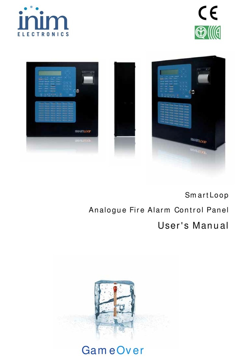
INIM Electronics
INIM Electronics SmartLoop User manual
INIM Electronics
INIM Electronics Prime060S User manual
INIM Electronics
INIM Electronics Prime Series User manual
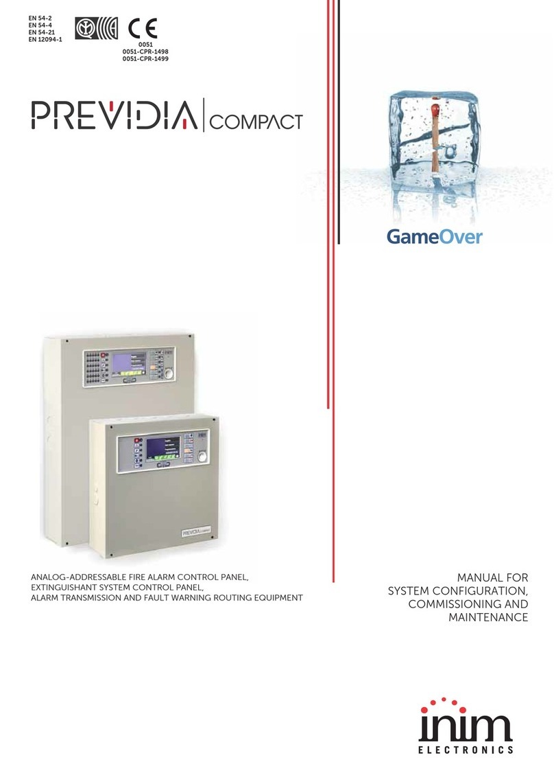
INIM Electronics
INIM Electronics Previdia Compact Quick guide
INIM Electronics
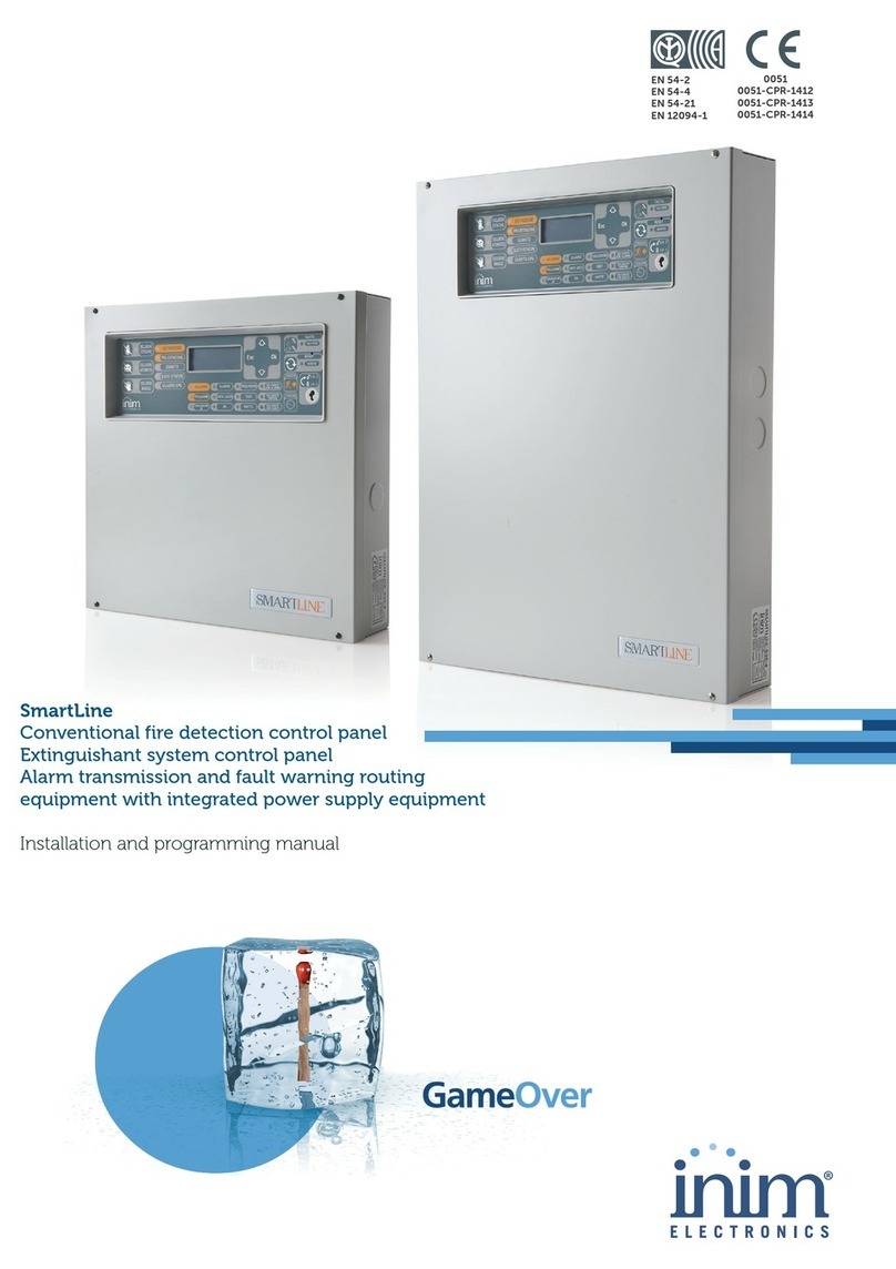
INIM Electronics SmartLine Series Assembly instructions
INIM Electronics
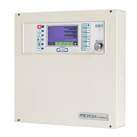
INIM Electronics Previdia Compact User manual

INIM Electronics
INIM Electronics Prime Series User manual

INIM Electronics
INIM Electronics SmartLoop User manual

INIM Electronics
INIM Electronics Previdia Compact User manual
INIM Electronics
INIM Electronics PREVIDIA MAX User manual
