Intergraph TDZ 2000 Quick start guide

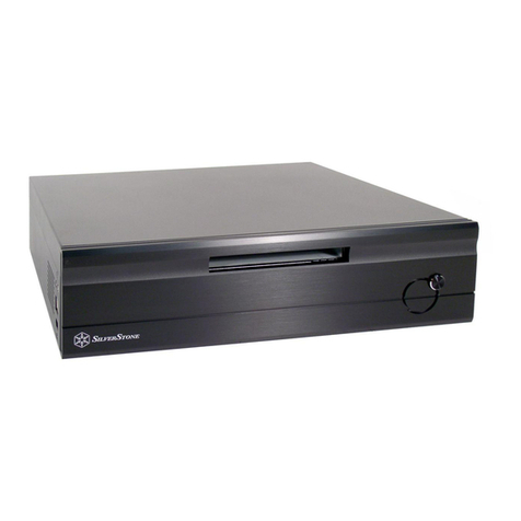
TowerMate Expansion Base
Installation and Use
October 1998
DHA025920

Copyright
1998 Intergraph Computer Systems. All rights reserved. This document contains information protected by copyright, trade secret, and
trademark law. This document may not, in whole or in part, be reproduced in any form or by any means, or be used to make any
derivative work, without written consent from Intergraph Computer Systems.
Use, duplication, or disclosure by the United States Government is subject to restrictions as set forth in subdivision (c)(1)(ii) of the rights in
technical data and computer software clause at DFARS 252.227-7013. Unpublished rights are reserved under the copyright laws of the
United States.
Intergraph Computer Systems, Huntsville AL 35894-0001
Notice
Information in this document is subject to change without notice and should not be considered a commitment by Intergraph Computer
Systems. Intergraph Computer Systems shall not be liable for technical or editorial errors in, or omissions from, this document. Intergraph
Computer Systems shall not be liable for incidental or consequential damages resulting from the furnishing or use of this document.
All warranties given by Intergraph Computer Systems about equipment or software are set forth in your purchase contract. Nothing stated
in, or implied by, this document or its contents shall be considered or deemed a modification or amendment of such warranties.
Trademarks
Intergraph Computer Systems
and the Intergraph Computer Systems logo are registered trademarks of Intergraph Computer Systems.
TowerMateand Ultra-towerare trademarks of Intergraph Computer Systems.
FCC/DOC Compliance
This equipment has been tested and found to comply with the limits for a Class B digital device, pursuant to part 15 of the FCC Rules.
These limits are designed to provide reasonable protection against harmful interference when the equipment is operated in a residential
installation. This equipment generates, uses, and can radiate radio frequency energy. If the equipment is not installed and used in
accordance with the instructions, it may cause harmful interference to radio communications. However, there is no guarantee that
interference will not occur in a particular installation.
If this equipment does cause harmful interference to radio or television reception, which can be determined by turning the equipment off
and on, try to correct the interference as follows: re-orient or relocate the affected device; increase the separation between this equipment
and the affected device; connect this equipment to an outlet on a circuit different from the circuit to which the affected device is connected;
consult a dealer or an experienced radio/television technician for help.
Changes or modifications made to the system that are not approved by the party responsible for compliance could void the user’s authority
to operate the equipment.
This Class B digital apparatus meets all requirements of the Canadian Interference-Causing Equipment Regulations. Cet appareil
numérique de la classe B respecte toutes les exigencies du Règlement sur le materiél brouilleur du Canada.
Warnings
Changes or modifications made to the system that are not approved by the party responsible for compliance could void the user's authority
to operate the equipment.
To reduce the risk of electrical shock, do not attempt to open the equipment unless instructed. Do not use a tool for purposes other than
instructed.
There is a danger of explosion if the battery is incorrectly replaced. Replace the battery only with the same or equivalent type as
recommended by the manufacturer. Dispose of used batteries according to the manufacturer's instructions.
There are no user serviceable parts in the power supply. Refer all servicing of the power supply to qualified service personnel.
To comply with FCC Class B limits, you must use shielded cables with this device.
Notes
This device is designed and manufactured to comply with approved safety standards for information processing and business equipment.
Read all operating instructions before using this device. Keep these instructions for future reference. Follow all warnings on the device or
in the operating instructions.


v
Contents
Preface.............................................................................................................................. vii
About This Document........................................................................................................ vii
Document Conventions...................................................................................................... vii
Customer Support.............................................................................................................viii
Hardware and Software Support Services............................................................viii
World Wide Web................................................................................................viii
Intergraph Bulletin Board Service .......................................................................viii
FAXLink............................................................................................................... ix
Telephone ............................................................................................................. ix
More Support Options........................................................................................... ix
1 Setting Up the TowerMate.............................................................................................. 1
Unpacking the TowerMate................................................................................................... 2
Understanding the Load Resistor Cable................................................................................ 2
TowerMate Overview........................................................................................................... 2
Connecting the Ultra-tower.................................................................................................. 4
What’s Next?....................................................................................................................... 6
2 Installing Cards and Devices .......................................................................................... 7
Opening the Expansion Base ............................................................................................... 8
Installing Expansion Cards .................................................................................................. 9
Installing Disk Drives ........................................................................................................ 11
Installing Peripheral Devices ............................................................................................. 13
What’s Next?..................................................................................................................... 15
3 TowerMate Reference................................................................................................... 17
System Features................................................................................................................. 18
Intrusion Alert Switch........................................................................................................ 18
TowerMate Power Operation ............................................................................................. 18
Disk Drive Delayed Start ................................................................................................... 19
Cable Access Panel............................................................................................................ 20
Ultra-tower BIOS............................................................................................................... 20
Symbios Ultra2 (LVD) SCSI Adapter................................................................................. 21
PCMCIA ........................................................................................................................... 21
PCI Buses and PCI Slots.................................................................................................... 22
Lithium Battery ................................................................................................................. 22
Power Supply..................................................................................................................... 23
P1 Pinout ............................................................................................................. 24
P2 - P5 Pinouts..................................................................................................... 25
P6 Pinout ............................................................................................................. 25

vi

vii
Preface
TowerMate Expansion Base Installation and Use provides information for setting up and
using the TowerMate expansion base. The TowerMate expansion is an affordable,
innovative docking base for Intergraph Computer Systems’ Ultra-tower systems. The
TowerMate offers:
u
Easy setup and connection to the Ultra-tower system base.
u
Either of the following, depending on the version:
− Four disk drive bays
− Three peripheral device bays
u
Five extra full-length, fully powered PCI expansion card slots.
u
Easy addition of disk drives and expansion cards, and easy servicing.
About This Document
TowerMate Expansion Base Installation and Use is organized as follows
u
Chapter 1, “Setting Up the TowerMate,” describes how to unpack and set up the
TowerMate for use.
u
Chapter 2, “Installing Cards and Devices,” describes how to open the TowerMate and
install expansion cards, extra disk drives, and other peripheral devices.
u
Chapter 3, “TowerMate Reference,” provides detailed information on system features,
functions, and procedures.
Document Conventions
Bold Commands, words, or characters that you key in literally.
Italic Variable values that you supply, or cross-references.
Monospace Output displayed on the screen.
SMALL CAPS Key names on the keyboard, such as D, ALT or F3; names of files and
directories. You can type filenames and directory names in the dialog boxes
or the command line in lowercase unless directed otherwise.
CTRL+DPress a key while simultaneously pressing another key; for example, press
CTRL and D simultaneously.

viii
Customer Support
Intergraph Computer Systems offers an assortment of customer support options.
Hardware and Software Support Services
Intergraph Computer Systems provides a variety of hardware services for Intergraph and
third-party equipment. Services include warranty upgrades, repair depot service, on-site
hardware maintenance, system administration, and network consulting. Hardware
purchased from Intergraph Computer Systems includes a factory warranty ranging from 30
days to three years. A detailed warranty description is available on the World Wide Web;
see the Support pages at http://www.intergraph.com/ics.
Intergraph Computer Systems provides complimentary software support for 30 or 90 days
following shipment of a hardware or software product. This includes World Wide Web
access, Intergraph Bulletin Board Service access, FAXLink service, and telephone (Help
Desk) support. At the end of the complimentary support period, you can purchase other
levels of software support.
World Wide Web
You can visit Intergraph Computer Systems on the World Wide Web at
http://www.intergraph.com/ics. On these pages, you can get news and product
information, technical support information, software updates and fixes, and more.
Intergraph Bulletin Board Service
On the Intergraph Bulletin Board Service (IBBS), you can get technical support information,
software updates and fixes, and more.
To connect to the IBBS:
1. Set your system’s communications protocol for eight (8) data bits, no parity, one (1) stop
bit, and any baud rate up to 14,400.
2. Using a modem, call 1-205-730-8786. Outside the United States, call one of the mirror
sites listed on World Wide Web; see the Software Support pages at
http://www.intergraph.com.
3. At the login prompt, key in your user ID. If you have not connected before, key in new
to create a user ID.
4. Follow the menus to find what you need. The IBBS provides clear choices and online
help.

ix
If you have trouble connecting to or using the IBBS, call the Customer Response Center at 1-
800-633-7248 (product entry IBBS) or leave a message for the IBBS System Operator at 1-
205-730-1413.
FAXLink
To use the FAXLink:
u
Call 1-800-240-4300 for information on how to get technical support information using
the FAXLink.
u
Call 1-205-730-9000 to get documents (up to five per call).
Telephone
To get customer support by telephone:
u
In the United States, call 1-800-633-7248 between the hours of 7:00 a.m. and 7:00 p.m.
Central Time, Monday through Friday (except holidays).
u
Outside the United States, contact your local Intergraph Computer Systems subsidiary or
distributor.
Have the following information available when you call:
u
Your service number, which identifies your site to Intergraph Computer Systems. You
use your service number for warranty or maintenance calls.
u
Your Customer Personal Identification Number (CPIN). You get a CPIN the first time
you call the Customer Response Center; it is associated with your service number for
future call logging.
u
The product’s name or model number.
u
The product’s serial number. Software product serial numbers are included in the
product packaging. Hardware product serial numbers are on a sticker affixed to the
hardware product.
u
Your name and telephone number.
u
A brief description of the question or problem.
More Support Options
To get information on more customer support options:
u
Visit the Support pages on the World Wide Web at http://www.intergraph.com/ics.
u
For hardware support questions in the United States, call 1-800-763-0242.

x
u
For software support questions in the United States, call 1-800-345-4856.
u
Outside the United States, contact your local Intergraph Computer Systems subsidiary or
distributor.

1
1 Setting Up the TowerMate
To expand an Ultra-tower system to its maximum capacity, the Ultra-tower mounts securely
atop the TowerMate expansion base using its cable-less, direct-connect docking mechanism.
This effectively extends the system board in the Ultra-tower to accommodate additional
device bays and expansion card slots.
Unpacking the TowerMate................................................................................................... 2
Understanding the Load Resistor Cable................................................................................ 2
TowerMate Overview........................................................................................................... 2
Connecting the Ultra-tower.................................................................................................. 4
What’s Next?....................................................................................................................... 6

2
Unpacking the TowerMate
Remove all items from the shipping carton and make sure you have the following items:
u
TowerMate expansion base
u
Power cable
u
TowerMate documentation
If any items are not included, contact the Intergraph Customer Response Center
immediately.
Understanding the Load Resistor Cable
The power supply in the TowerMate requires that a power-consuming card or device be
installed before it will activate.
A Load Resistor Cable is shipped with the TowerMate, which produces an instant load when
connected to an active power supply. This ensures that the TowerMate will power on even
with no cards or devices installed. If you purchased a TowerMate with at least one open
device bay, the Load Resistor Cable was pre-installed. Remove the cable if you need to
install a device into the bay where the Load Resistor Cable is installed.
If you purchased a TowerMate with no open bays, the Load Resistor Cable was shipped in
the Accessory Box. Install this cable if you remove all cards and devices but still want to use
the system. For more information, see Chapter 2, “Installing Cards and Devices.”
WARNING Vital system components inside the TowerMate could be damaged if you power on the
TowerMate without any power-consuming devices installed. Alternatively, install the
load resistor cable into one of the device bays.
TowerMate Overview
NOTE For the sake of simplicity, only one color of TowerMate is shown in this document.
WARNING Do not lift the TowerMate by either the front plastic cover or by the metal interface
connector, as shown in the following figure. Attempting to do so may cause the
indicated parts to break, damaging the system, and might result in the TowerMate
dropping, causing bodily damage.
Examine the top of the expansion base and notice the spring-loaded tabs, alignment studs,
and interface connector, as shown below.

3
Studs
Tabs
Interface connector
Do not lift here!
Do not lift here!
The Ultra-tower fits onto the alignment studs, and then slides into position so the interface
connector on the expansion base fits into the ISA connector on the Ultra-tower system board,
as shown in the following figure. When correctly positioned, the spring-loaded tabs pop into
view, securing the left side of the Ultra-tower.
Studs Tabs Studs
Interface connectorISA connector

4
Connecting the Ultra-tower
To connect the Ultra-tower to the TowerMate:
1. If the Ultra-tower is powered on, shut down the system and turn off system power.
2. Disconnect the cables and the AC power cord from the Ultra-tower.
3. Remove the top cover from the Ultra-tower by grasping the lip at the rear of the top
cover and then pulling the release, located beneath the lip, upward at a 45 degree angle,
as shown in the following figure.
4. Remove the left side panel from the Ultra-tower. Lift up the panel by the side cowling
and slide it back and off the Ultra-tower.
NOTE For detailed information on how to open the Ultra-tower, see the
System
Reference
delivered
with the Ultra-tower system.
Press up on release
located under lip
Left side panel
5. If an ISA card is installed, remove it and reinstall it into the ISA slot in the TowerMate.
See Chapter 2, “Installing Cards and Devices,” for more information.
NOTE If your Ultra-tower system is equipped with a PCMCIA solution, in addition to moving the ISA
adapter card to the ISA slot in the TowerMate, you must also move the PC Card Swapbox to
an open bay in the TowerMate, due to EMI control regulations and cable length limitations.
For more information, see Chapter 3, “TowerMate
Reference.”
6. Remove the panel from the bottom of the Ultra-tower. Some versions of the Ultra-tower
use two screws to secure the bottom panel, one in each corner of the left side. Other
versions use a single screw, in the middle of the left side. To remove the bottom panel
from the Ultra-tower, remove the appropriate screw(s).
7. Place the TowerMate expansion base in the desired work location.
8. Lift the Ultra-tower and set it on top of the TowerMate expansion base. The alignment
studs fit into holes in the bottom of the Ultra-tower system.

5
NOTE Face the left side of the system, so that you can see inside the Ultra-tower. This will make it
easier to ensure that each alignment stud fits into each hole.
CAUTION Do not pick up the Ultra-tower by the top cover (back) or the lower part of the faceplate
(front). The system could fall and cause personal injury or damage to equipment. See the
System Setup
document delivered with the Ultra-tower system for more information.
9. While facing the left side of the Ultra-tower, pull the bottom towards you until the
spring-lock tabs pop up on the inside edge of the chassis frame. The interface connector
should insert into the ISA connector on the Ultra-tower system board, as shown in the
following figure.
Studs Tabs Studs
Interface connectorISA connector
10. Replace the side panel and top cover of the Ultra-tower.
11. If you removed an ISA card from the Ultra-tower, install it into the ISA connector in the
TowerMate, as described in Chapter 2. If necessary, relocate the Symbios SCSI adapter
from the TowerMate’s shared PCI slot to a non-shared PCI slot. See Chapter 3,
“TowerMate Reference,” for more information.
12. Make sure the AC voltage switch on the back panel of the TowerMate is set to the
proper line voltage for your location. If your location uses 115 volts, make sure the
number 115 is visible on the switch. If your location uses 230 volts, make sure the
number 230 is visible on the switch.
WARNING If you do not set the AC voltage switch correctly, serious damage to the TowerMate
and its components may result when you turn on power to the system.
13. Connect the TowerMate power cord to the appropriate power source.
14. Reconnect the cables and AC power cord to the Ultra-tower. The system powers on but
does not start.

6
WARNING To power the TowerMate from the Ultra-tower, the power supply in the Ultra-tower
must be rated at 500 watts or greater. Attempting to power the TowerMate from an
Ultra-tower equipped with a power supply rated at less than 500 watts may prevent the
system from operating and may damage vital system components. To determine the
power supply rating of your Ultra-tower system, see the documentation accompanying
the Ultra-tower.
AC receptacle
for TowerMate
What’s Next?
If installing expansion cards, disk drives, or other peripherals in the TowerMate, go to
Chapter 2, “Installing Cards and Devices” to open the TowerMate and install your options.

7
2 Installing Cards and Devices
There are two versions of the TowerMate expansion base; one version is designed to
vertically accommodate 3½-inch disk drives in four internal bays, and the other is designed
to horizontally accommodate 5¼-inch peripheral devices or 3½-inch disk drives in three
front-accessible bays. Both versions are equipped with five PCI slots, one shared PCI/ISA
slot, and one Symbios Ultra2 (LVD) SCSI adapter. This chapter describes how to install
expansion cards into the slots, and hard disk drives and peripheral devices into the bays.
Opening the Expansion Base ............................................................................................... 8
Installing Expansion Cards .................................................................................................. 9
Installing Disk Drives ........................................................................................................ 11
Installing Peripheral Devices ............................................................................................. 13
What’s Next?..................................................................................................................... 15

8
Opening the Expansion Base
Remove the side panels from the TowerMate to gain access to the interior. As viewed from
the front, the left side of the TowerMate contains peripheral device and hard disk drive bays;
the right side contains the option card slots. The side panels are secured by thumb screws, as
shown in the following figure.
Thumb
screws Thumb
screws
To remove a TowerMate side panel:
1. Remove the thumb screws and slide the panel to the rear, as shown in the following
figure.
Slide panel toward rear

9
2. Lift the bottom of the panel out, and then lift the panel up, as shown in the following
figure.
Lift panel out,
then up
Installing Expansion Cards
The TowerMate contains five PCI slots and one shared PCI/ISA slot. The shared PCI slot
and the second PCI slot are both Secondary bus slots; the remaining four PCI slots are
Tertiary bus slots. See Chapter 3, “TowerMate Reference,” for more information. Refer to
the expansion card documentation for details on the bus with which each card works best.
NOTE Graphics cards are not supported in the TowerMate.
To install expansion cards:
1. Disconnect the power cords from the TowerMate and the Ultra-tower.
2. Remove the right side panel from the TowerMate. The expansion board slots are shown
in the following figure.

10
Shared
PCI/ISA
slot
PCI slot
(5)
Blanking screw (6)
Blanking plate (6)
Ribbon cable
pass-through Lithium
battery
3. Remove the blanking plate screw and blanking plate from the slot, shown in the
previous figure, in which you want to install the expansion card.
4. Install the expansion card. Push firmly at the center of the card until it fully seats into
the slot.
NOTE If you have a PC Card (PCMCIA) ISA adapter, you must move it to the ISA slot in the
TowerMate, since the TowerMate uses the ISA slot in the Ultra-tower.
5. Secure the expansion card to the chassis using the screw removed previously.
6. Remove the cable access panel from the top of the TowerMate.
7. Connect any necessary cables to the expansion card. If you are installing a disk
controller or PC Card adapter, route the ribbon cable through the ribbon cable pass-
through opening to the left of the I/O card, as shown in the previous figure.
8. Replace the side panel and cable access panel.
NOTE The TowerMate is equipped with a safety interlock system that prevents the unit from
powering on unless the panels are installed. Always replace the panels before attempting to
boot the system.
9. Reconnect the power cords to the TowerMate and Ultra-tower.
10. Install the required drivers for the expansion card and configure them for use as
described in the expansion card documentation.
Other manuals for TDZ 2000
2
This manual suits for next models
1
Table of contents
Other Intergraph Computer Accessories manuals

Intergraph
Intergraph ExtremeZ SAN Instruction Manual

Intergraph
Intergraph ExtremeZ SAN User manual

Intergraph
Intergraph ImageStation Z and use Quick start guide

Intergraph
Intergraph ImageStation ZII and use Quick start guide

Intergraph
Intergraph ErgoView Stand User manual

Intergraph
Intergraph Fibre Channel User manual

Intergraph
Intergraph InterServe 8000 Manual

Intergraph
Intergraph Ergonomics User manual

Intergraph
Intergraph InterServe 3x5 Manual

Intergraph
Intergraph StudioZ GT RAX User guide