manuals.online logo
Brands
  1. Home
  2. •
  3. Brands
  4. •
  5. IPEX
  6. •
  7. Cables And Connectors
  8. •
  9. IPEX CABLINE-VS User manual

IPEX CABLINE-VS User manual

1/ 16
Document No.
HIM
-
08004
Confidential C
I
-
PEX Inc. QKE
-
DFFDE09
-
03 REV.8
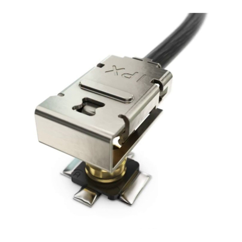
CABLINE®-VS
Part No. Plug: 20453-*##T-*** Receptacle: 20455-*##E-***
Instruction Manual
5 S19019 January 8, 2019 Y.Miyazaki T.Masunaga H.Ikari
4 S18402 July 2, 2018 A.Koyanagi T.Masunaga H.Ikari
3 S17909 December 12, 2017
Y.Miyazaki T.Masunaga H.Ikari
2 S14495 December 2, 2014
H.Ikari J.Tateishi E.Kawabe
Rev. ECN Date Prepared by Checked by Approved by
CABLINE
®
-
VS
Instruction Manual
Document No.
HIM
-
08004
2/ 16
Confidential C
弊社、CABLINE-VS CONN.の取り扱いに際して、本コネクタを安全に御使用頂くことを目的とし、
コネクタの挿入・抜去の手順及び注意点を記述致します。
This manual provides the mating & un-mating methods and cautions to handle CABLINE-VS connector properly.
为了能够使作业员正确地,安全地使用我司的 CABLINE-VS 系列连接器,特此编写了这份在插拔作业时的方法以及注意事
项。
【対象コネクタ名称・型番】 / Connector Name, Part number / 对象连接器名称・料号
◆ケーブル側コネクタ (The cable side connector / 线端的连接器)
名称 / Product Name / 名称:CABLINE-VS PLUG
型番 / Part No. / 料号 :20453-※**T-※※※
1 : With PULL BAR
2 : Without PULL BAR
3 :With INSULATION PULL BAR
◆基板側コネクタ (The PCB side connector /板端连接器)
名称 / Product Name / 名称 : CABLINE-VS RECEPTACLE
型番 / Part No. / 料号 : 20455-※**E-※※※
“**”には各芯数番号が入ります。
(“**”表示相应的芯数。/‘**’ part shows the number of the connector position).
“※”はバリエーションになります。詳細は図面を参照願います。
(“※”表示不同的种类。具体内容请参照图纸。)
(‘※’ part shows the variation. Please refer to a drawing for the details.)
【コネクタ各部名称】 Names of each part of the connector. / 连接器各个部品名称
【コネクタ挿入手順 / Connector Mating Method / 连接器插入方法】
ケーブル側コネクタ
PLUG
线端的连接器
PULL TAPE
拖拉胶带
基板側コネクタ
Receptacle
板端连接器
嵌合基準
マーク
Datum pin mark
基准 Pin 记号
嵌合方向
Mating direction
插入方向
PULL BAR
拉环
I
-
PEX MARK
CABLINE
®
-
VS
Instruction Manual
Document No.
HIM
-
08004
3/ 16
Confidential C
1.ケーブル側コネクタのセット方法(Direction to mate. / 线端连接器设置方法)
図1のように、基板側コネクタの基準 pin にケーブル側コネクタの基準 pin がくるように、セットします。
As shown in Fig.1, please set so that the datum pin mark of the cable connector and the PCB connector
are matched.
如图 1所示,将板端的连接器的基准 Pin 记号与线端的连接器的基准 Pin 记号对齐设置好。
DATUM MARK 無の場合 / For the connector without DATUM MARK. / 没有基准 Pin 记号的情况
ケーブル側コネクタの I-PEX MARK が上面にくるように、セットします。
Please set so that I-PEX MARK of the cable connector is upper side.
将线端的连接器有“I-PEX”的一面向上设置。
図1(Fig.1)
2.嵌合方法(How to mate. /插入方法)
図2のように、ケーブル側コネクタの両側を水平に押し、ロック穴にロックが掛かると、嵌合完了となります。
As shown in Fig.2, push both ends of cable side connector horizontally until the lock is locked.
如图 2所示,按压线端连接器的两侧,将连接器水平插入。当 Plug 上锁扣凸点被锁住后,表明已经完
全插入到正确位置。
図2(Fig.2)
コネクタ両側を水平に押す
Push both ends of connector horizontally.
按压
Plug
的两端,将
Plug
水平插入
ロックが掛かっている事を確認
Check the lock is locked.
确认锁扣凸点有被锁住
ケーブル側コネクタ基準 pin
Datum pin of cable side connector.
线端的连接器的基准 Pin 记号
ロックが掛かっている事を確認
Check the lock is locked.
确认锁扣凸点有被锁住
I-PEX MARK
基板側コネクタ基準 pin
Datum pin of PCB side connector.
板端的连接器的基准 Pin 记号
隙間がないか確認
Confirm whether there is space.
确认此处没有间隙
⇒
Plug shell とRece shell がオーバーラップ
している事を確認
Check the overlap of Plug shell and Rece shell.
请确认Plug 的SHELL 与RECE 的SHELL
Plug
shell
Rece shell
CABLINE
®
-
VS
Instruction Manual
Document No.
HIM
-
08004
4/ 16
Confidential C
PULL BAR 付の場合 / For the connector with PULL BAR. / 装有拉环的情况
図3のように仮挿し状態時に、PULL BAR を基板側コネクタ側に回転させ、ケーブル側コネクタの両側を
水平に押す。そして、突き当て面に隙間がないか確認する。
From temporary inserting condition as shown in Fig.3, turn PULL BAR to the PCB connector side and push both ends of cable side connector
horizontally. Then, confirm whether there is space between mating confirmation surfaces.
如图 3所示,在准备插入时,将拉环向着板端连接器一侧进行翻转,然后按压线端连接器的两侧,将连接器水平插入
到正确位置。确认接触面部分没有间隙。
図 3(Fig.3)
嵌合が完了後、PULL BAR を基板側に押し込み、基板側コネクタの SHELL とロックさせる。
After mated, push PULL BAR to the PCB side and lock it to SHELL of the PCB side connector.
插入到正确位置以后,将拉环沿着板端连接器的侧边向下压,使拉环与板端连接器的 SHELL 能够
进行锁住。
図4(Fig.4)
確認内容 Contents of confirmation. / 确认内容:
図5(Fig.5)
コネクタ両側を水平に押す
Push both ends of connector horizontally.
按压 Plug 的两端,将 Plug 水平插入
隙間がないか確認
Confirm whether there is space.
确认此处没有间隙
ロックが掛かっている事を確認
Check the lock is locked. / 此处的锁扣有被锁好
隙間がないか確認
Confirm whether there is space.
确认此处没有间隙
ロックが掛かっている事を確認
Check the lock is locked.
此处的锁扣有被锁好
CABLINE
®
-
VS
Instruction Manual
Document No.
HIM
-
08004
5/ 16
Confidential C
注意事項 / Cautions. / 注意事项
片側ずつ押すと、隙間が発生する恐れが有ります。(図 6)
When you push one end by one end, there is possibility to cause a gap. (Fig.6)
如果只按压一侧,有可能产生插入不到位的状况。(接触面会产生间隙)(图6)
図6(Fig.6)
挿入する際、PLUG に下向きの力を入れながら挿入すると、PCB に傷が入りパターンが断線したり、ショート
したりする可能性がありますので、下向きの力は加えないようにしてください。
If you apply downward force from connector above especially edge of pull bar when you insert Plug
into Receptacle, there is a possibility to damage PCB like picture below. This downward force on edge of
pull bar will be cause of short and circuit and disconnection of PCB Layout. Therefore, please do not apply
any load from above.
在进行插入作业时,在 Plug 的正上方不能施加向下的力,如果施加向下的力,有可能会在 PCB 板上
造成伤痕甚至会破坏 PCB 里面的线路。
隙間発生 NG 状態
A gap occurs. NG
接触面会产生间隙
片側挿入 1
Push the one side.
只按压一侧
1
片側挿入 2
Push the one side.
只按压一侧 2
NG
挿入方向
Inserting
direction
傷発生
Scr
atch occurred
. /
有伤痕发生
CABLINE
®
-
VS
Instruction Manual
Document No.
HIM
-
08004
6/ 16
Confidential C
PULL BAR 付の場合 / For the connector with PULL BAR. / 装有拉环的情况
図7-1,2 のように挿入時に PULL BAR を押しながらまたは引っ張りながら挿入すると、PULL BAR が変形したり、回転軸がコネクタから
抜ける恐れがありますので、行わないでください。
When mating, in case you mate the connector pushing PULL BAR as shown in Fig.7-1,2, there are possibilities to cause PULL BAR
deformation or the rotation axis dropping out from the connector. Please don’t push PULL BAR.
如图 7-1,2 所示,在进行插入作业时,如果直接按压拉环,会导致拉环变形,或者拉环的回转
轴从连接器脱落,所以请绝对不要直接按压拉环进行插入作业。
図7-1(Fig.7-1)
図7-2(Fig.7-2)
回転軸
Rotation axis.
回转轴
PULL BAR をコネクタの挿入に使用しないでください。
插入和拔出连接器时请不要推拉环。
Please don’t use PULL BAR for insertion of connector.
。
CABLINE
®
-
VS
Instruction Manual
Document No.
HIM
-
08004
7/ 16
Confidential C
図7-3 のように Pull-tape を嵌合方向に強く引っ張ると、PULL BAR が変形したり、回転軸がコネクタから抜ける恐れが
ありますので、行わないでください。
Do not extract the pull-tape forcedly toward mating direction. It may deform the pull bar or rotation axis may come off from the connector.
如图7-3 那样以插入方向强拽拖拉胶带的话,将导致拉环变形或拉环回转轴从连接器脱落的风险,所以请不要这样做。
図7-3(Fig.7-3)
図7-4 のように PULL-BAR を矢印に強く引っ張ると、PULL BAR が変形したり、回転軸がコネクタから抜ける恐れが
ありますので、行わないでください。
Do not pull the pull-bar toward arrowed direction. It may deform the pull bar or rotation axis may come f from the connector.
如图7-4 那样以箭头方向拖拽拉环的话,将导致拉环变形或拉环从连接器脱落的风险,所以请不要这样做。
図7-4(Fig.7-4)
CABLINE
®
-
VS
Instruction Manual
Document No.
HIM
-
08004
8/ 16
Confidential C
水平方向 Horizontal direction. / 水平方向
本コネクタを安全に使用して頂く為に下写真の様にこじり角を 5°以下で御願い致します。
仮差しの状態から片側のみを挿入した場合、下図の様にこじり MAX.値が 5°となります。
5°以下であればコネクタの変形は発生致しません。
To use this connector safely, please keep mating slant 5° or less as shown in the figure below.
When you insert only one side in the temporary insert condition, maximum slant degree will become 5°.
By keeping the slant 5° or less, deformation of the connector doesn't occur.
为了能够使安全的使用此连接器,请注意在插入时,插入角度应该不大于 5°。如下图所示。
如果在预备插入时,只是按压一侧的状况下,那么斜着插入的角度也不应该大于 5°。如下图所示。
5°以下进行插入时,那么连接器不会发生变形的不良。
5°こじり状態 / 5°slanted condition. / 斜插角度 5°
垂直方向 Vertical Direction. / 垂直方向
コネクタ挿入開始時の許容角度は下図の通りです。
The acceptable angle to start connector mating is below.
最初的连接器插入的允许角度如下图所示。
挿入開始時の許容角度 8°
The acceptable angle to start connector insertion is 8°.
最初的连接器插入的允许角度 8°以下
5°
挿入開始時の許容角度 5°
The acceptable angle to start connector insertion is 5°.
最初的连接器插入的允许角度 5°以下
CABLINE
®
-
VS
Instruction Manual
Document No.
HIM
-
08004
9/ 16
Confidential C
下図のように、RECE. SHELL に挿入ガイドが設定されています。
ガイドに沿って挿入を御願い致します。ガイドに沿って挿入頂ければコネクタの変形は発生致しません。
RECEPTACLE SHELL has an insertion guide as shown in the figure below.
Please insert connector along this guide.
As long as inserting along the guide, deformation of the connector doesn't occur.
如下图所示,在板端连接器内部的 SHELL 上设置有导向弹片。
请沿着导向弹片进行插入作业。沿着导向弹片进行插入作业的话,连接器不会发生变形。
SHELL 裏面のガイド形状
The guide shape on back side of SHELL. / SHELL 内部的导向弹片形状
CABLINE
®
-
VS
Instruction Manual
Document No.
HIM
-
08004
10 / 16
Confidential C
【コネクタ抜去手順 / Connector Un-mating Method. / 连接器拔出方法】
・コネクタを抜去する。Un-mating the connector. /将连接器拔出。
図8のように基板側コネクタに対し、ケーブル側コネクタの両側を矢印方向に平行に抜去する。
As shown in Fig.8, hold both ends of the cable side connector and un-mating it parallel to the arrowed direction from the PCB side
connector.
如图 8所示,将线端的连接器从板端的连接器沿着箭头所示方向水平拔出。
平行抜去 OK 状態 / parallel un-mating OK condition こじり抜去 NG 状態 / Slanted un-mating NG condition
水平拔出 OK 状态 斜着拔出 NG 状态
図8(Fig.8)
PULL TAPE 付PULL BAR の場合
/ For the connector with PULL BAR with PULL TAPE. / 在拉环上贴有胶带的情况
まず、PULL-TAPE を①の方向に引っ張り、基板側コネクタとのロックを解除後、
②の方向に PULL BAR を回転させ、基板に平行に③の方向に引っ張り、抜去を行う。
注意: ×印の方向へ PULL-TAPE を持ち上げようとすると、コネクタが破損する恐れがあります。
First, pull PULL-TAPE to the direction ①and release the lock with the PCB connector. Then, turn PULL BAR to the direction ②and pull
it to the direction ③in parallel with PCB to un-mate the connector.
Caution: In pulling PULL-TAPE to the direction ×mark, there are possibilities to cause
the PCB connector deformation
首先,将胶带向着①的方向拉出,使拉环与板端的连接器的锁扣解除以后,按照②的方向将拉环
旋转,使其与 PCB 基板平行。最后沿着③的方向将连接器拔出。
注意:如果沿着×印的方向向上拉出胶带,可能会导致连接器破损。
図9(Fig.9)
Withdrawal direction
×
0
°~
60
°
0
°~
90
°
①
②
③
CABLINE
®
-
VS
Instruction Manual
Document No.
HIM
-
08004
11 / 16
Confidential C
INSULATION PULL BAR の場合 / For the connector with INSULATION PULL BAR
抜去手順Ⅰ/Un-mating method Ⅰ
図10 の①の箇所のどちらか一方を②の方向に PULL BAR を上げ、基板側コネクタとのロックを解除後、
③の方向に PULL BAR を回転させる。抜去は図 8と同様の方法にて行う。
注意: ①以外で PULL-BAR を②方向に上げようとすると、PULL BAR が変形したり、コネクタが
破損する恐れがあります。
また、INSULATION PULL BAR の絶縁コート部を抜去に使用すると、PULL BAR が変形する
可能性がありますので、抜去には使用しないでください。
なお、絶縁コート部に金属や硬いものを当てると、コートが剥がれてしまう恐れがありますので、
当てないようにご注意願います。
Raise one of ①points of PULL BAR in Fig.10 to the ②direction to release the lock with the PCB side connector, then, turn PULL BAR
to ③direction. Un-mating method is same as described in Fig.8.
Caution: Except for ①part, if you pull up the PULL-BAR towards direction ②, PULL BAR would have
deformation or the connector would have damage. Also, if you use Insulated part of INSULATION
PULL BAR for Un-mating, PULL BAR may deform. Please do not use it for Un-mating. Moreover,
if you hit the metal or hard material onto the insulating part, the coating have possibility to peel off
so that please understand to handle it carefully.
使用绝缘镀层的拉环的情况
连接器拔出方法 Ⅰ
如图 10 所示,先将两端的①这个地方的拉环向着②这个方向挑起来(两端无论哪一端都可以)
解除拉环与板端连接器的锁扣,再沿着③这个方向使拉环旋转至水平
拔去连接器的方法与图 8所示方法相同。
注意:在①以外的其他地方将拉环沿着②方向向上挑起的话,有可能会导致拉环变形或者连接器产生
破损的危险。
绝缘镀层物质如果接触到金属或其他坚硬的物质,会使绝缘镀层脱落,因此务必注意防止
绝缘镀层与硬物接触。
図10(Fig.10)
③
①
②
絶縁
コート
部
/ Insulated part. /
绝缘镀层部分
①
CABLINE
®
-
VS
Instruction Manual
Document No.
HIM
-
08004
12 / 16
Confidential C
抜去手順 Ⅱ/ Un-mating method Ⅱ
図10 の①の箇所のどちらか一方を、②の方向に PULL BAR を上げ、基板側コネクタとのロックを解除後、
図11 のように垂直になるように PULL BAR を回転させ、図 12 のように③の垂直なっている箇所を
矢印方向に基板と水平方向になるように抜去してください。
注意: ①以外で PULL-BAR を②方向に上げようとすると、PULL BAR が変形したり、コネクタが
破損する恐れがあります。
また、INSULATION PULL BAR の絶縁コート部を抜去に使用すると、PULL BAR が変形する
可能性がありますので、抜去には使用しないでください。
なお、絶縁コート部に金属や硬いものを当てると、コートが剥がれてしまう恐れがありますので、
当てないようにご注意願います。
As Fig 10, ①, pull the one of ①points of PULL BAR up towards ②direction to release the lock
from the PCB side connector and turn PULL BAR up to horizontal as Fig 11. As Fig 12,
please make un-mating by pulling the horizontal part ③in parallel to PCB.
Caution: Except for ①part, if you pull up the PULL-BAR towards direction ②, PULL BAR would have
deformation or the connector would have damage. Also, if you use Insulated part of INSULATION
PULL BAR for Un-mating, PULL BAR may deform. Please do not use it for Un-mating. Moreover,
if you hit the metal or hard material onto the insulating part, the coating have possibility to peel off
so that please understand to handle it carefully.
使用绝缘镀层的拉环的情况
连接器拔出方法 Ⅱ
如图 10 所示,将①部位中的其中一侧沿着②的方向把 PULL BAR 抬起,接触与基板上的连接器的锁扣。然后,将 PULL BAR
旋转到如图 11 所示的垂直位置,之后沿着箭头方向水平的将 Plug 拔出。
注意:如果抬起 Pull Bar 时,使用①部位以外的其他部位,那么可能会引起 Pull Bar 变形,连接器破损等不良现象。
其次,如果使用金属等比较坚硬的东西去触碰 Pull Bar 的绝缘镀层部位,会造成绝缘层脱落,所以要避免这类现
象发生。
図11(Fig.11)
図12(Fig.12)
②
③③
CABLINE
®
-
VS
Instruction Manual
Document No.
HIM
-
08004
13 / 16
Confidential C
本コネクタを安全に使用して頂く為に下図の様にこじり角を 5°以下で御願い致します。
5°以下であればコネクタの変形は発生致しません。
To use this connector safely, please keep insert slant 5° or less as shown in the figure below.
By keeping the slant 5° or less, deformation of the connector doesn't occur.
为了能够使安全的使用此连接器,请注意在拔出时,角度应该不大于 5°,如下图所示。
5°以下进行拔去作业,不会导致连接器变形等不良现象。
5°こじり状態 / 5°slanted condition / 5°斜着拔出状态
注意事項 / Cautions. / 注意事项
※ケ-ブル断線の恐れが御座いますのでケーブルを手に持ってのコネクタ挿抜は御控え下さい。
この様な挿抜を行いますと、ケ-ブルが局部的に大きな力が生じ、ケ-ブル芯線が
切れる恐れが有ります。特に数本での斜め引張りの場合、十分御注意下さい。
In case you un-mate connector by pulling cable, there is possibility to break the cable. Please avoid such an un-mating method. In
addition, such an un-mating can cause locally-force to cable and the inner conductor can be damaged. Especially, slanted un-mating by
holding some cables is more dangerous. Please be careful.
※因为会导致 Cable 被拉断的危险,所以禁止用手直接拿住 Cable 将连接器拔出。
如果直接拿住 Cable 进行拔出作业,有较大的力施加在 Cable 上,可能会导致 Cable 的芯线断裂。
特别要禁止只是拿住少数几根 Cable 斜着将连接器拉出。请特别注意不要发生此类情况。
NG NG
5
°
CABLINE
®
-
VS
Instruction Manual
Document No.
HIM
-
08004
14 / 16
Confidential C
抜去する際、PLUG に下向きの力を入れながら抜去すると、PCB に傷が入りパターンが断線したり、ショート
したりする可能性がありますので、下向きの力は加えないようにしてください。
If you apply downward force from connector above especially edge of pull bar when you un-plug from
Receptacle, there is a possibility to damage PCB like picture below. This downward force on edge of
pull bar will be cause of short and circuit and disconnection of PCB Layout. Therefore, please do not apply
any load from above.
在进行拔出作业时,在 Plug 的正上方不能施加向下的力,如果施加向下的力,有可能会在 PCB 板上
造成伤痕甚至会破坏 PCB 里面的线路导致短路或者断路的危险。
【コネクタ取扱の注意】(CAUTION IN CABLE CONNECTOR HANDLING. /使用连接器的注意事项)
ケーブルを垂直方向に引っ張ると、下写真の様に基板側コネクタのシェルが変形する恐れがありますので
行わないで下さい。
また、PULL BAR に関しても同様に、垂直方向に引っ張らないようにお願いいたします。
In case the cable is pulled to the vertical direction, SHELL of the PCB side connector can deform. Please don’t pull vertically. Similarly, PULL
BAR should not be pulled to the vertical direction.
如果将 Cable 垂直往上拉,会产生如图所示的 SHELL 发生变形的不良,请您不要如此进行作业。
当然,拉环也是同样的情况,也不能垂直往上拉。
垂直荷重 / Vertical load / 垂直受力 シェル変形 / Shell deformation. / SHELL 发生变形
Shell turns up
NG
抜去方向
傷発生
/ Scr
atch occurred
. /
有伤痕发生
CABLINE
®
-
VS
Instruction Manual
Document No.
HIM
-
08004
15 / 16
Confidential C
・ケーブルコネクタの取り回しの際には特定のケーブルに引っ張り力が集中しないように配慮ください。
・コネクタのケーブル取り付け部に引っ張り力及び繰り返し変位が加わらないように配慮ください。
・In a cable harnessing work, be careful NOT to apply the pulling force to specific cables.
・Be careful NOT to apply the pulling force or repeated bending force to the cable attachment part of a plug connector.
・将Cable 整形成特定的形状时,应该避免特定的 Cable 产生集中的受力。
・在靠近连接器部分的 Cable 上不要施加拉力或者持续的震动。
図13 (Fig.13)
・図14 のように、矢印方向に常に力が加わるようなケーブルの引き回しを行うと、嵌合外れやコネクタの破損等
の恐れがありますので、ご注意願います。
・Continuous force of the direction shown in black arrow in Fig. 14 can damage connectors or cause the coming off from receptacle connector.
Please be careful NOT to apply such force.
・请注意,避免如图 14 所示的那样沿着箭头方向在 Cable 上施加外力使 Cable 发生转向,因为这样做
会使连接器产生脱落或者损坏。
図14(Fig.14)
ケーブルを固定し、コネクタのケーブル取り付け部に外
力が加わらないように配慮ください。
Fix the cable so that the external force is NOT
applied to the cable attachment part of connector.
将此处的
Cable
进行固定,为了使在靠近连接器部分
コネクタのケーブル取り付け部
Cable attachment part of Connector.
靠近连接器部分的 Cable
CABLINE
®
-
VS
Instruction Manual
Document No.
HIM
-
08004
16 / 16
Confidential C
【電気検査に PLUG を使用する際の注意】(Cautions for electrical inspection when using plug/
电测时使用 PLUG 的注意事项)
PLUG Housing が損傷・変形している状態で PLUG Housing を Receptacle に挿入すると、
Receptacle の破損・座屈やピッチズレによる短絡等の恐れがありますので、ご注意願います。
Please note that damage, buckling and offset will occur on the receptacle when the receptacle is inserted into
the damaged or distorted plug housing, and it may cause short circuit.
使用 Housing 损伤变形状态的 PLUG 插入 Receptacle,有发生 Receptacle 破损,端子弯折或错位等导致短路的风险,
请注意。
PLUG を使用して電気検査を行う場合、電気検査用 PLUG (Part No. 20490-0**T)の使用を推奨します。
Plug for electrical inspection (Part No. 20490-0**T) is recommended in case of electrical inspections.
使用 PLUG 进行电测的场合,推荐请使用电测专用 PLUG(料号:20490-0**T)。
図15(Fig.15)
Housing 損傷
Housing damage
Contact 変形
Contact distortion
Housing 損傷
Housing damage
PLUG Housing が損傷・変形している状態で
Receptacle に挿入しないで下さい
Do not insert deformed plug housing into receptacle.
请不要插入已变形或损坏的 PLUG 进入Receptacle 里面。

This manual suits for next models

125

Other IPEX Cables And Connectors manuals
IPEX MHF 7S User manual

IPEX

IPEX MHF 7S User manual

IPEX CABLINE-CA PLUG User manual

IPEX

IPEX CABLINE-CA PLUG User manual

IPEX CABLINE-UY User manual

IPEX

IPEX CABLINE-UY User manual

IPEX MINIFLEX 5-BF II User manual

IPEX

IPEX MINIFLEX 5-BF II User manual

IPEX CABLINE-UA II PLUG User manual

IPEX

IPEX CABLINE-UA II PLUG User manual

IPEX CABLINE-VS IIF User manual

IPEX

IPEX CABLINE-VS IIF User manual

IPEX CABLINE-UM PLUG User manual

IPEX

IPEX CABLINE-UM PLUG User manual

IPEX ISH20P User manual

IPEX

IPEX ISH20P User manual

IPEX MINIFLEX 2-BF LK User manual

IPEX

IPEX MINIFLEX 2-BF LK User manual

IPEX MHF-A User manual

IPEX

IPEX MHF-A User manual

IPEX MINIFLEX 175-ST User manual

IPEX

IPEX MINIFLEX 175-ST User manual

IPEX CABLINE-CX II PLUG Without Cover User manual

IPEX

IPEX CABLINE-CX II PLUG Without Cover User manual

IPEX MP-A 03 User manual

IPEX

IPEX MP-A 03 User manual

IPEX CABLINE-CAL PLUG User manual

IPEX

IPEX CABLINE-CAL PLUG User manual

IPEX CABLINE-VSF User manual

IPEX

IPEX CABLINE-VSF User manual

IPEX CABLINE-CA IIF User manual

IPEX

IPEX CABLINE-CA IIF User manual

IPEX CABLINE-CAF User manual

IPEX

IPEX CABLINE-CAF User manual

IPEX EVAFLEX 5-SE-GHT User manual

IPEX

IPEX EVAFLEX 5-SE-GHT User manual
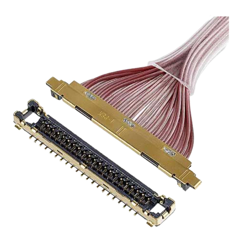
IPEX CABLINE-VS IIF User manual

IPEX

IPEX CABLINE-VS IIF User manual
IPEX FPL II User manual

IPEX

IPEX FPL II User manual

IPEX 20613-0 E-0 Series User manual

IPEX

IPEX 20613-0 E-0 Series User manual

IPEX CABLINE-UY 20857-0 T-0 Series User manual

IPEX

IPEX CABLINE-UY 20857-0 T-0 Series User manual

IPEX CABLINE-CAF User manual

IPEX

IPEX CABLINE-CAF User manual

IPEX MHF I User manual

IPEX

IPEX MHF I User manual
Popular Cables And Connectors manuals by other brands

EMO Systems E335 Instructions for use

EMO Systems

EMO Systems E335 Instructions for use

OUNEVA OLE 25-95 installation guide

OUNEVA

OUNEVA OLE 25-95 installation guide

LEGRAND RJ 45-Cat 5e quick start guide

LEGRAND

LEGRAND RJ 45-Cat 5e quick start guide

Redarc SBI12KIT manual

Redarc

Redarc SBI12KIT manual

Viessmann 5056 Operation manual

Viessmann

Viessmann 5056 Operation manual

Philips SWV2113W Specifications

Philips

Philips SWV2113W Specifications

Cablesson HDelity user manual

Cablesson

Cablesson HDelity user manual

OUNEVA VG03-0001 installation guide

OUNEVA

OUNEVA VG03-0001 installation guide

Philips SWV3530 Specifications

Philips

Philips SWV3530 Specifications

Telegärtner STX IP20 RJ45 Plug AWG24-27 Cat.6 Assembly instructions

Telegärtner

Telegärtner STX IP20 RJ45 Plug AWG24-27 Cat.6 Assembly instructions

Panduit CRB6BL installation instructions

Panduit

Panduit CRB6BL installation instructions

Speaka Professional SP-1676616 operating instructions

Speaka Professional

Speaka Professional SP-1676616 operating instructions

Cypress CLUX-3D12S1A Operation manual

Cypress

Cypress CLUX-3D12S1A Operation manual

Philips SWA4555S/10 Information

Philips

Philips SWA4555S/10 Information

Melchioni MK-911-2plus user manual

Melchioni

Melchioni MK-911-2plus user manual

Philips SWA4536W/10 user manual

Philips

Philips SWA4536W/10 user manual

Channel Master CM-3201 LTE Filter instruction sheet

Channel Master

Channel Master CM-3201 LTE Filter instruction sheet

ADC Triaxial Camera Connectors ProAx Specification sheet

ADC

ADC Triaxial Camera Connectors ProAx Specification sheet

manuals.online logo
manuals.online logoBrands
  • About & Mission
  • Contact us
  • Privacy Policy
  • Terms and Conditions

Copyright 2025 Manuals.Online. All Rights Reserved.