IQAir GC series User manual

GC Series
High-Performance Air Cleaning System
User’s Manual HB GCSer_GB_0407 / 105.10.35.12
Swiss Made

3
About This User’s Manual
Congratulations on your purchase of this QAir® high-performance air cleaning system.Please study this user manual
carefully to familiarize yourself with the special features and functions of your QAir® system and keep it in a safe
place for future reference.
Read these instructions before using the appliance:
•Do not use this appliance as sole protection against harmful pollutants.
•Do not immerse the appliance in water or other liquids.
•Always disconnect the power from your air cleaner by unplugging the power cable before adding or removing
parts and before cleaning.
•Do not operate this appliance if it has a damaged cord or plug, if the motor fan fails to rotate, if it is not working
properly, if it has been dropped or damaged, or immersed in water.
•f the mains cord of this appliance should become damaged, it may be replaced with a similar cord set, as is
commonly used for computers and similar appliances.
•Only use this appliance for its intended purpose of air cleaning in non-industrial environments.
•Do not use this appliance in areas with very high concentrations of dusts or powder to prevent the danger of dust
explosions.
•Do not use this appliance in explosive areas.
•Only use filters and accessories recommended by QAir®.
•Do not use outdoors.
•Do not obstruct the air inlet and air outlet of the air cleaner.
•Do not place the appliance on a soft surface such as a bed or other soft furnishings.
•Only use this appliance in an upright position.
•Do not place next to a humidifier.
•Keep the power cord away from heated surfaces.
•Save these instructions for future reference.
Important Safety Instructions
QAir® reserves the right to change specifications contained in this document at any time and without prior notice.
© 1998–2007 QAir® Group. All rights reserved. QAir® is the registered trademark of the QAir® Group. EvenFlow™ is a trademark of the QAir® Group. QAir®
systems and filters are protected under U.S.patents 6 001145 and 6 159 260. Other U.S.,
European and Asian patents pending.

4
Page
Important Safety Instructions 3
Chapter 1 – Air Cleaning Systems and Indoor Air Quality 5
1. 1 mproving ndoor Air Quality 5
Chapter 2 – Setting Up 6
2. 1 Unpacking 6
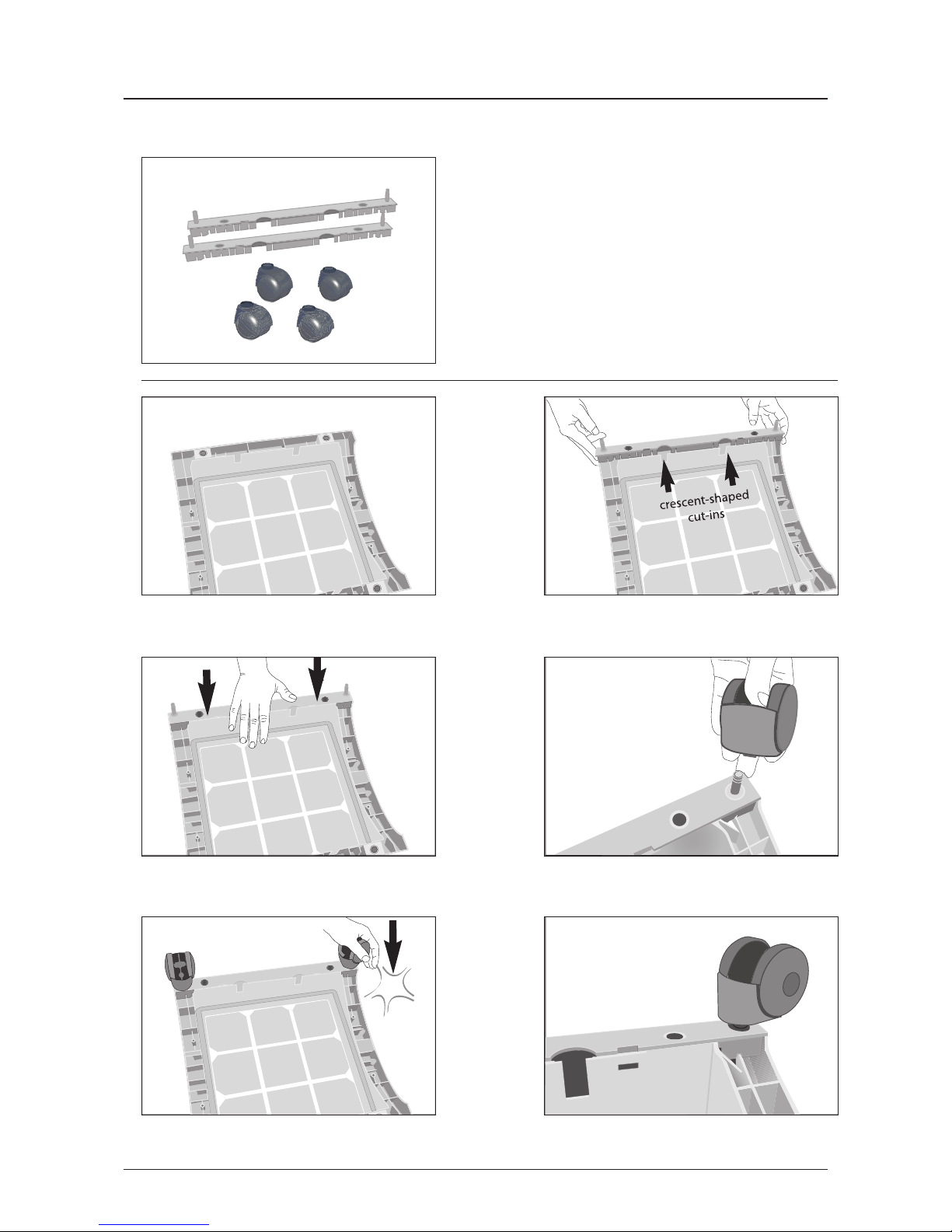
2. 2 Fitting Your Air Purifier with Casters 7
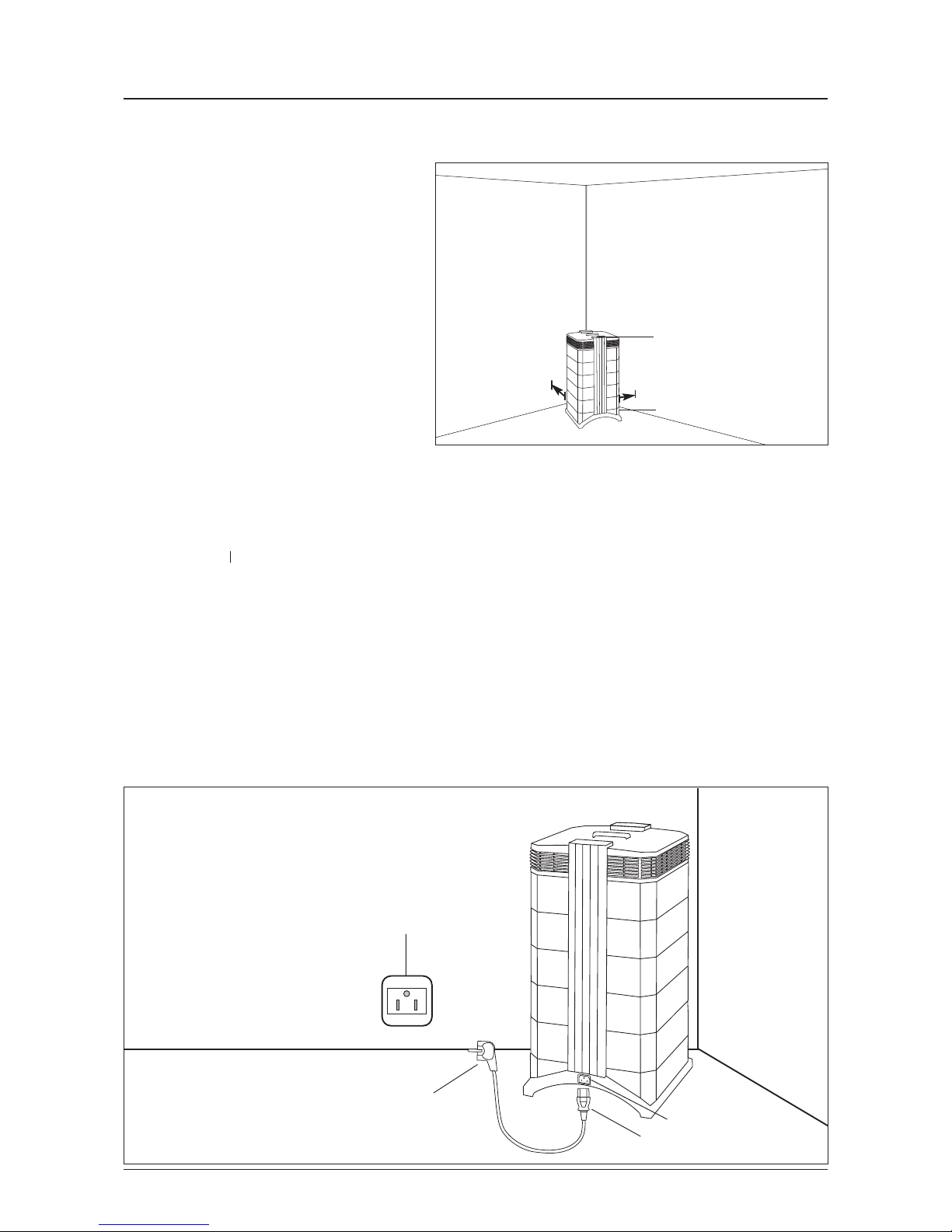
2. 3 Choosing a Suitable Location 8
2. 4 Connecting to Power 8
Chapter 3 – The IQAir® System’s Components 9
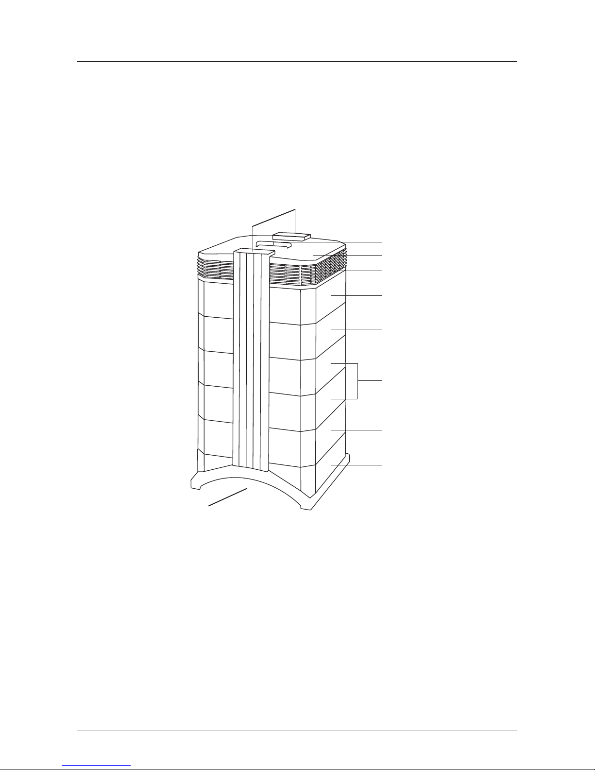
3. 1 Description of Housing Components 8
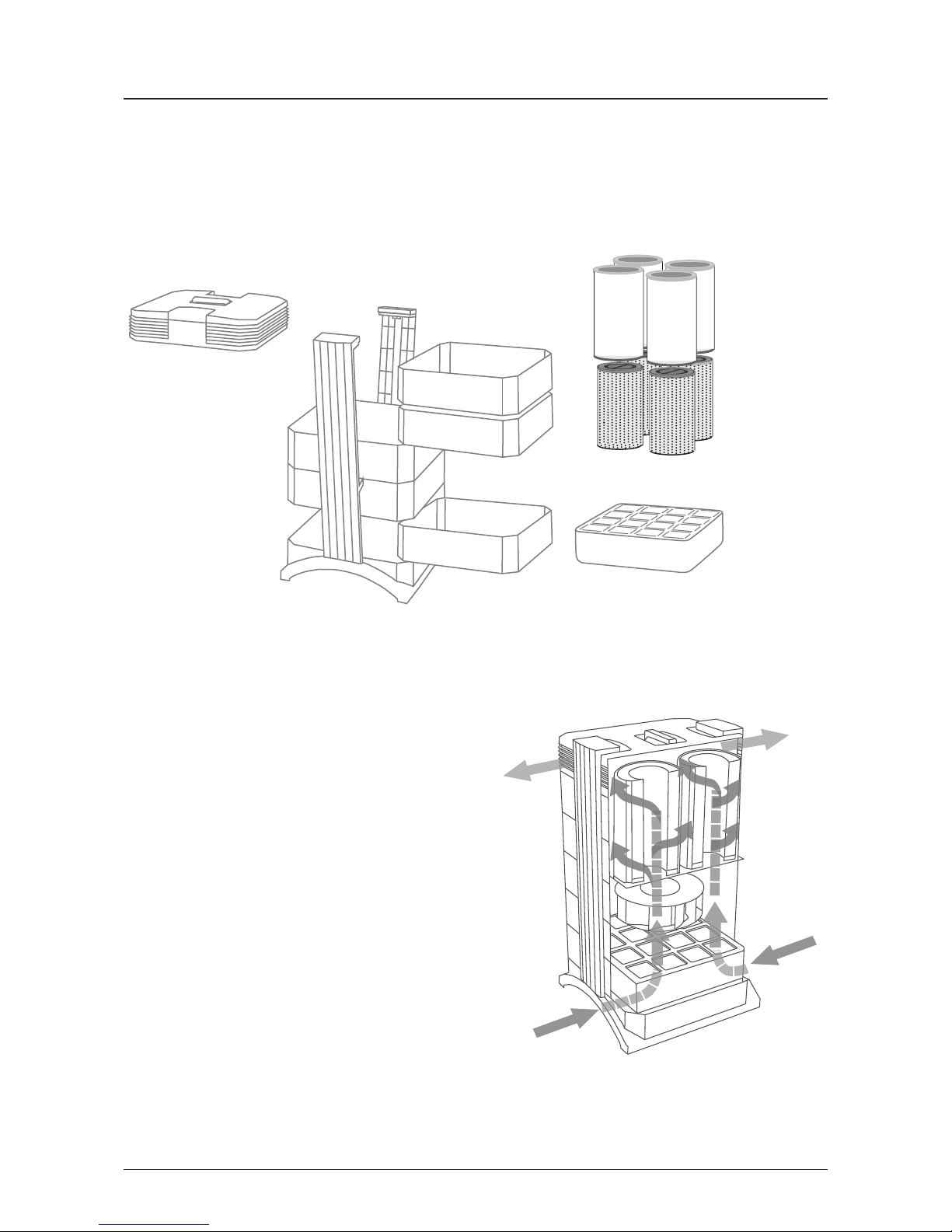
3. 2 Description of Removable Components 10
3. 3 How the QAir® System Works 10
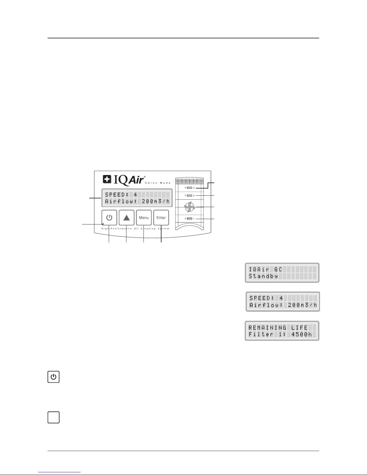
Chapter 4 – Using the Control Panel 11
4. 1 Description of Control Panel 11
4. 1. 1 Description of Control Panel Keys 11
4. 2 Control Panel Locking Function 12
4. 3 Fan Speed and Air Delivery 12
4. 3. 1 Regulating Fan Speed 12
4. 3. 2 Air Exchange Rates in Differently Sized Rooms 13
4. 4 Using the Menu Functions 13
4. 4. 1 Menu Overview 13
4. 4. 2 Filter Life Monitor 14
4. 4. 3 Setting the Daily Timer 15
4. 4. 4 Setting the Weekly Timer 16
4. 4. 5 Timer ON/OFF Fan Speed Selection 16
4. 4. 6 Timer nformation in the Control Panel 17
4. 4. 7 Time & Day Setting 17
4. 4. 8 Filter Life Reset 18
4. 4. 9 Changing Airflow Units 18
4. 4. 10 Language Setting 18
4. 4. 11 Filter Load ndex Setting 19
4. 4. 11.1 Determining the Filter Load ndex 19
4. 4. 11.2 Modifying the Filter Load ndex 20
Chapter 5 – Using the Remote Control 21
5. 1 Remote Control Functions 21
5. 2 Getting the Best Transmission Results 21
5. 3 Placing Batteries in the Remote Control 22
Chapter 6 – Replacing Filters 22
6. 1 Location of the Filters 22
6. 2 Ordering Replacement Filters 22
6. 3 Opening and Closing the Housing 23
6. 3. 1 Troubleshooting when Closing the Housing 23
6. 4 Replacing the Pre-Filter (Filter 1) 23
6. 5 Replacing the Gas Phase Filter Cartridges (Filter 2 & 3) 24
6. 6 Discarding Used Filters 25
Chapter 7 – Maintenance 25
7. 1 Cleaning the Housing 25
7. 2 Maintenance-Free Fan 25
Chapter 8 – IQAir® Accessories (Optional) 26
Table of Contents

5
Chapter 1 – Improving Indoor Air Quality
Chapter 1 – Air Cleaning Systems and Indoor Air Quality
1.1 Improving Indoor Air Quality
Air cleaning can play an important role when it comes to improving indoor air quality. However, it should be noted
that air cleaning should be used in conjunction with pollution source control and ventilation, wherever possible.
Strategy to improve indoor air quality
To tackle any indoor air quality problem, keep the following three-step strategy in mind:
1. Eliminate or reduce the air pollution source as much as possible.Source control is by far the most effective way to
improve indoor air quality, since it sets out to deal with air pollution at the point of origin.
2. Ensure that sufficient fresh air is entering the room from outside. Air cleaners are not a substitution for sufficient
ventilation. They are not able to reverse the conversion of oxygen (O2) into carbon dioxide (CO2), caused by
breathing and combustion processes.
3. Ensure the QAir system can clean enough air to cope with your room size.The actual hourly air volume cleaned
by the system should be at least double the air volume of your room. f the rate at which pollutants enter the room
air is high or the indoor air quality requirements are stringent, the hourly air delivery of the system needs to
exceed the room air volume several times.To achieve that level of air turnover,it may be necessary to employ more
than one system.
Air Cleaning Results
Although air cleaners may be advertised and sold to be suitable for use in specific indoor environments and to deal
with specific indoor air quality problems, the manufacturer and distributors make no claim as to the specific air
cleaning results that are achieved under the user’s individual operating conditions.The air quality improvements that
can be realized with the QAir® system (as with any air cleaner) in indoor environments depends to a significant
degree on circumstantial factors, which are out of the control of the manufacturer or distributors. mportant factors
which will influence the air quality improvements that can be achieved in an indoor environment with an air cleaner
include:
•Type of air pollutants present
•ntensity of the pollutant source(s)
•Pollutant concentration
•Size of the indoor environment (room size)
•Operating speed of the unit
•Number of air cleaners placed in the indoor environment
•Saturation state of the filters in the air cleaner
Consult a qualified specialist to determine an effective and comprehensive indoor air quality strategy.

6
Chapter 2 – Setting p
Chapter 2 – Setting Up
2.1 Unpacking
To unpack the QAir system, open the top of the box and remove the square styrofoam pad which contains all
accessories and product literature. Lay the box on its side, hold the system by the handle and pull it out of the box.
Remove the plastic bag and foam belt. Keep the packaging for future transport and service needs.
Power cord
(plug types vary)
IQAir®
Advanced Air Cleaning System
TechnicalSuppor t
Shouldtechnical problems arise during or after the warranty period, please contact your point of purchase.
Toexpedite your service request, please give the following information when contacting us:
• Model
• Ar ticle and serial number (found at the base of the unit)
• Your details (name, address, phone, e-mail)
• Date of purchase
• D escription of problem
Ordering Replacement Filters
Pleasecontact your point of purchase for all your filter replacement needs.
How to Register your Air Cleaning System
Pleasecomplete and return the below card soon after purchase. The information will allow us to provide you with a
swiftser vice should service work become necessary.At your request we will also keep you up-to-date with technical
and promotional information relating to this air cleaning system.( The shell and serial numbers are locatedat the
baseof the system).
IQHB-ZB-3yGar.NE 1903 GB
WarrantyRegistration Card
(Allinformation is treated confidentially and will not be supplied to third parties)
Article No: 1
LL LLL LLL
Serial No.:
LLL
.
LLLLLL
Yourname: Company:
Address: City: Postcode:
Dealername: City: Postcode:
Purchasedate:
Theair cleaning system is used for:
If you would like to be notified about new products and promotions,please enter your e-mail address or phone
numberhere:
Pleasedetach this card and return it to the point of purchase.
✃
Warranty &Service Information
GC Series
Advanced Air Cleaning System
User’s Manual
GCSeries GB 220/60 Neutral 1402
SwissMade
User manual Certificate of
Performance
Set of casters Warranty Card and
Technical Specifications
Remote control
including battery
4 gas phase filter cartridges
Note: The gas phase filter cartridges for the air cleaner are
supplied in a separate box and must be installed before use.
4 post filter sleeves
Note: The sleeves are supplied inside the QAir system. Pull the
post filter sleeves over the cartridges before installing the
cartridges in the air cleaner.

7
Chapter 2 – Setting p
Attaching the supplied casters is optional.They make it
easy to move the air purifier between rooms.
Attention: Please be careful and roll the unit gently when
moving it over thresholds or other obstacles to avoid
breakage.
The Mobility Caster kit consists of:
1. mounting rail (x 2)
2. casters (x 4)
For installation simply follow the below instructions:
CLICK
12
34
56
Turn the device upside down on a soft and clean
surface.
Place the mounting rail on the purifier’s base so that
the holes line up with the black connector pins on the
base.The cut-ins should face the center of the unit.
Press down until the mounting rail snaps into place.
Repeat with second rail.
Place the caster onto caster pin.
Press on caster, until it snaps into place. Repeat steps
4 and 5 with the remaining casters.
Ensure that each caster is securely fitted before
placing the air purifier in its upright position onto
the casters.
2.2 Fitting Your Air Purifier with Casters

8
Chapter 2 – Setting p
2.3 Choosing a Suitable ocation
When choosing a suitable location for the
QAir system, keep the following
considerations in mind:
•Choosing the most suitable room for the
system will depend on where you would
like the focus of the air cleaning efforts.Two
main considerations are the time you spend
in a particular room and the location of the
main air pollution sources.As a general rule,
the closer the system is located to the air
pollution source, the better the air cleaning
performance in the room. Although an air
cleaning result may be achieved in adjacent
rooms, the main air cleaning will take place
in the room where the system is located.For
the best air cleaning results in adjacent
rooms,make sure that doors to these rooms
are left wide open.
•For best performance, the system should be positioned at least 30 cm (1 foot) away from the nearest vertical
surface, such as a wall or a cupboard. n general, the more centrally the system is positioned, the better the
performance.
•Position the system close to a power outlet and make sure that the power cable is positioned in a way that it does
not present an obstacle that could be tripped over.
•Make sure that the system is positioned in such a way that the control panel is easily accessible.
2.4 Connecting to Power
1. Plug the connector end of the power cord into the recessed power inlet socket on the back of the system.
2. Plug the other end of the power cord into a power outlet or power strip.
Important: The only way to disconnect power completely is to unplug the power cord.
Do not use the IQAir® system when the power cord becomes damaged.The power cord may be replaced with an
approved cord with a two-pole plug.These power cords are commonly used for computers and similar appliances.
Power cord plug
(plug type can vary) Power inlet socket
min. distance
30cm/12”
Keep power cable
clear of walk-ways
Control panel should
be easily accessible
Power outlet
Power cord
connector Power cord connector

9
Chapter 3 – The IQAir® System’s Components
3.1 Description of Housing Components
The QAir system features a modular tower design in which all important filtration and air moving components are
positioned vertically in-line, i.e. stacked on top of another. Air is drawn into the system at the base, and passes
through several filter stages to be returned to the room via the diffuser on top of the system.The housing modules
are held together by two locking arms.
•The base with its arched design features air intake openings on two sides.
•The Frame module 1 consists of frame 1 and the Pre-Filter which is fixed inside the frame by four filter clamps.
•The fan assembly comprises two housing modules with the centrifugal fan inside.
•The Frame module 2 consists of frame 2 and a steel base plate in which the four gas phase filter cartridges are
fixed by means of a bayonet locking system.
•Frame module 3 covers the 4 gas phase cartridges and filter sleeves.
•The EvenFlow™ diffuser features the omni-directional air outlet openings.
•The handle on top of the diffuser is designed for carrying the QAir® system.
•The locking arms hold the housing elements together. When opened, the locking arms allow easy access to all
filters.
EvenFlow™ diffuser
Frame module 1
Fan assembly
Frame module 2
Frame module 3
ocking arms
Base
Handle
Air intake opening
Air outlet openings

10
Chapter 3 – The IQAir® System’s Components
1.Room air is drawn into the system via two arched open-
ings at the base.
2. The air is drawn in through the HEPA pre-filter that al-
ready removes most pollution particles.
3. At the heart of the system, sandwiched between the
filters, is a powerful centrifugal fan which generates the
airflow.
4. The air is pushed through four cartridges that contain
up to 7,8 kg of gas phase control media, which retains
specific chemical pollutants.
5. Particulate post-filter sleeves hold back abrasion
particles from the gas phase filter media.
6.Low turbulence,low velocity air is returned to the room
via the EvenFlow™ diffuser.
3.2 Description of Removable Components
The QAir system features a modular housing design which enables the easy replacement of all filters in a matter of
seconds. The illustration below shows all the removable components. For more details on how to replace filters,
please refer to Chapter 6 – Replacing Filters.
3.3 How the IQAir® System Works
Gas phase filter
cartridges
Pre-filter
Frame 2
Frame 1
Frame 3
filter clamps
EvenFlow™ Diffuser
Post filter sleeves
1
2
3
4
6
5

11
Chapter 4 – sing the Control Panel
4.1.1 Description of Control Panel Keys
Power Key
The Power key switches the QAir® ystem on and off. When the system is switched off, the fan stops to run, but
the system will remain connected to the power supply (standby mode).The standby mode allows for automatic timer
start-up. n the standby mode, the different menu functions can be accessed.
Tip: n a menu window the Power key also serves as a quick exit key to return to the main display window.
Arrow () Key
When the system is switched on,the key allows the adjustment of the fan speed. n the enter mode,indicated
by the appearance of a black flashing cursor (see“Enter Key”below),the key is used to modify the selected setting
in the display window. Confirmed with the Enter key, the enter mode is automatically terminated.The LCD will then
display the current menu settings for another 15 seconds before reverting to the main window display.
Chapter 4 – Using the Control Panel
The QAir system is operated and controlled via the electronic control panel which is located at the top of the front
locking arm.
Several operations can be completed via the electronic control panel, including:
•Switching the system on and off
•Controlling the fan speed and corresponding air delivery rate
•Checking the remaining filter life of the individual filters
•Setting the automatic timer
•Resetting the Filter Life Monitor after replacing a filter
•Locking the control panel to avoid tampering with the system’s settings
•Choosing the desired display language
4.1 Description of Control Panel Elements
CD = Liquid
Crystal Display
Power
Key Enter
Key
Menu
Key
Arrow
Key
Filter Life LED: Filter 3
Filter Life LED: Filter 2
Pre-filter Life LED: Filter 1
Timer LED
Fan Speed LEDs
CD Display
The 2-line LCD displays important information about the system’s settings. n
standby mode, the first line shows the current day and time. f the timer is
activated,the programmed start and stop times will be displayed on the second
line.
f the QAir system is on, the first line displays the current speed setting and the
second line displays the corresponding air delivery rate of the system. By
pressing the Menu key, ten active menu functions may be accessed. These
functions are explained in detail in this chapter.
ED = Light Emitting Diode
Main window: Standby mode
Main window: On mode
Menu window: Filter Life monitor
▲

12
Chapter 4 – sing the Control Panel
Menu Key
The Menu key allows access to any one of eleven menus.Pressing the Menu key once allows access to the first
menu function. Pressing the Menu key twice allows access to the second menu function, and so on. f no key is
pressed for 15 seconds in a menu window, the display will revert to the main display window. Tip: f you are in a
menu window and would like to remain in the window for more than 15 seconds, keep the key depressed.
Enter Key
The Enter key, if pressed for 3 seconds, allows the modification of a setting. The enter mode is indicated by a
flashing cursor on the modifiable setting. Pressing the Enter key again will save any entry and move the cursor to
the next modifiable item in the display window.When the last modifiable choice in a window is confirmed with the
Enter key, the enter mode is automatically terminated and the new settings are saved.
Filter ife EDs: Whenever the system is on, the colour of the filter life LEDs (light emitting diodes) indicates the
state of the individual filters in the system. Note: The positions of the filter life LEDs on the control panel correspond
to the actual positions of the filters within the system.
The filter life indicator LEDs signal four possible stages in the life of the filter:
1. Green: The filter is still within 80% of its estimated life span.
2. Orange: The filter is approaching the last 20% of its estimated life span.
3. Red: The filter has reached the end of its estimated life span.
4. Red blinking: The filter has passed its estimated life span and should be replaced immediately.The QAir system’s
effectiveness is likely to have been reduced dramatically, either due to a reduction in airflow
(particle filters are clogged) or a reduction in filter efficiency (gas phase filter is saturated).
Fan Speed EDs: These LEDs simulate the fan speed through the frequency of their rotation.The faster the rotation
of the fan speed LEDs, the faster the actual fan speed of the unit.
4.2 Control Panel ocking Function
The control panel can be locked to avoid tampering with the settings.To
lock or unlock the control panel keys, the Menu and the Enter key have
to be pressed down simultaneously for 3 seconds.The activated locking
function is indicated with a star symbol in the control panel display.The
locking function is cancelled by disrupting the power supply.
4.3 Fan Speed and Air Delivery
The QAir system can be set to run at six different fan speeds which correspond to six different airflow rates. Speed
1 is the lower, speed 6 the highest fan speed. The higher the fan speed, the more room air will be filtered by the
system. The high fan speed settings provide additional air cleaning power to deal with situations of elevated
pollution levels.
To allow better evaluation of the system’s performance at different fan speeds, the standard display window shows
not only the fan speed, but also the air delivery rate (airflow). The displayed airflow is factory preset and is not
measured by the system itself.
4.3.1 Regulating Fan Speed
1. When the QAir system is switched off (standby mode),the first line of the LCD
display shows the model name. To switched the system on, press the Power
key on the far left of the control panel.
2. The LCD now displays the fan speed and the corresponding airflow rate.Note:
The system starts at the fan speed at which it was running when it was last
used.
3. To change the fan speed, press the key.
Enter
▲
Menu
E

4.3.2 Air Exchange Rates in Differently Sized Rooms
Any air cleaner can only be effective if it filters a sufficient amount of air in an indoor environment. For general air
cleaning purposes, the QAir system should be able to filter the room air volume at least twice every hour on the set
fan speed to achieve a significant air quality improvement. f the intensity of the pollution source is high or a high
degree of purification is needed, more air changes may become necessary. n order to achieve the desired number
of air changes, more than one air cleaner may be required.
The number of air changes that are necessary to attain a certain level of indoor air quality will depend on a variety
of factors, including:
•intensity of air pollution source: The higher the rate at which air pollutants are produced or enter the indoor
environment, the higher the air cleaning rate in the room needs to be.
•filtration efficiency for specific air pollutants: The lower the filtration efficiency for certain pollutants, the more
air changes are required to reduce these pollutants.
•desired improvement in air quality: The higher the desired improvement in air quality, the more air changes are
required.
The number of ACH produced by an QAir system in a specific environment are calculated as follows:
hourly air delivery of the QAir system (m3/h)
= air changes per hour (ACH)
air volume of the room (m3)
N.B.The air delivery rates at the various fan speeds settings are listed on the “Technical Specifications”sheet.
Example calculation: A room with the dimensions of 4x 4 x 2.6 meters has an air volume of 41.6m3.With an air
delivery rate of 240 m3/h,the room air volume will be circulated over 5.7 times per hour by the
QAir® system (240 m3/h ÷ 41.6 m3= 5.77 ACH).
4.4 Using the Menu Functions
The QAir control panel offers a choice of several menu options which allow access to the advanced features of the
system. n total there are ten active menu functions.The functions can be accessed in standby or running mode.
4.4.1 Menu Overview
Pressing the Menu key accesses the menu functions in the following order:
1. Filter ife Monitor
Allows the viewing of the remaining filter life of the individual filter
elements within the system.
2. Daily Timer
Allows to activate the timer and set the daily ON period.
3. Weekly Timer
Allows to deactivate the daily ON period on certain days of the week.
4. Timer ON Fan Speed Selection
Allows to set the fan speed for the Timer ON period.
5. Timer OFF Fan Speed Selection
Allows to set the fan speed outside the Timer ON period.
6. Time & Day Setting
Allows to set the current time and day setting.
13
Chapter 4 – sing the Control Panel

4.4.2 Filter ife Monitor
The QAir system is equipped with an electronic Filter Life Monitor that calculates the remaining life of the system’s
filters.Thanks to the Filter Life Monitor, the user does not have to guess when filters need to be replaced or replace
them at fixed intervals (which rarely correspond to the actual amount of use). The Filter Life Monitor watches over
the most important factors affecting the life of the individual filters. The Filter Life Monitor display shows the
remaining life of each individual filter at any given time.
1. To reach the Filter Life Monitor display from the main display window,
press the Menu key once.The remaining life of the filter 1 will appear.
2. Press the key to view the remaining life of the other filters in the system.
3. The remaining life of the filters is expressed in hours of operation at the
current speed setting and the programmed filter load indices.
How the Filter ife Monitor Works
The basis for the calculation of the remaining filter life is the already elapsed operation time at the set fan speeds and
filter load indices during that period. This input is compared with an internal memory bank which contains infor-
mation about the different filters’ lives under specific conditions of use.
The Filter Life Monitor makes a calculation of the remaining filter life, taking into account not only past use of the
system, but also likely future use. As reference for future use, the filter life monitor uses the fan speed and the filter
load indices which are programmed at the time.
The relationship between the current fan speed, the current filter load indices and the remaining filter life displayed
can be expressed as follows:
•The higher the current fan speed setting, the shorter the displayed remaining filter life.
•The higher the current filter load index setting, the shorter the remaining filter life displayed for the affected filter.
7. Filter ife Reset
Allows the resetting of the filter life counter after replacing a filter
element.
8. Airflow Units
Allows to switch the airflow units between cfm (cubic feet per minute)
and m3/h (cubic meters per hour).
9. anguage
Allows the modification of the display language.
10. Filter oad Index Setting
Allows the modification of the air pollution index, so the system can
calculate the remaining filter life, taking pollution intensity into account.
11. Service Access
This menu is designed for factory access only.
14
Chapter 4 – sing the Control Panel

15
Chapter 4 – sing the Control Panel
timer status field
start time end time
4.4.3 Setting the Daily Timer
The Daily Timer Menu allows the setting of a Timer ON period, which is defined
by a start time and an end time. For the Timer ON period, a fan speed can be
selected in the Timer ON Fan Speed Menu (see 4.4.5).The time outside the Timer
ON period is defined as the Timer OFF period for which the air cleaner can be
switched off or for which a different fan speed can be selected in the Timer OFF
Fan Speed Selection Menu (see 4.4.5).
The timer status field indicates whether the timer function is enabled or disabled
and allows the user to quickly enable/disable the timer e.g. for holiday.
1. To reach the Daily Timer Menu from the main display window, press the
Menu key twice.
2. Press and hold the Enter key until the cursor starts to flash.
3. Press the key once to activate the timer.
Note: f the start and stop time are identical, the timer cannot be activated.
4. Press the Enter key to save the timer status setting and to proceed to the
start time.
5. Select the desired start hour by pressing the key.
6. Press the Enter key to save the start hour and to proceed to the minute
setting.
7. Select the desired start minute setting by pressing the key.
Note: The minute settings can only be set in five minute increments.
8. Press the Enter key to save the start time and to proceed to the stop time
setting.
9. Select the desired stop hour by pressing the key.
10. Press the Enter key to save the stop hour and to proceed to the minute
setting.
11. Select the desired minute setting by pressing the key.
12. Press the Enter key to save the minute setting and to exit the enter mode

16
Chapter 4 – sing the Control Panel
4.4.5 Timer ON/OFF Fan Speed Selection
The Timer ON/OFF Fan Speed Selection Menu allows the programming of two
different fan speeds for two different time periods (referred to as Timer ON an
Timer OFF periods). For the Timer ON period you can select between fan speeds
1 to 6.For the Timer OFF period you can select between fan speeds 0 (i.e.off) to 6.
1. To reach the Timer ON Fan Speed Selection Menu from the main display
window, press the Menu key four times.
2. Press and hold the Enter key until the cursor appears.
3. Press the key to select the desired speed for the Timer ON period.
4. Press the Enter key to confirm the chosen speed and to exit the enter mode.
5. To set the fan speed for the Timer OFF period press the Menu key one more
time. Press the Enter key until the cursor appears and adjust the Timer OFF
fan speed as above. The final Enter command saves the selection exits the
enter mode.
4.4.4 Setting the Weekly Timer
The weekly timer allows the activation/deactivation of the Timer ON period on
certain days of the week. n its default setting the timer is enabled on all seven
days of the week.This is indicated by stars below the abbreviations of the days.
On days, without a star, the air cleaner will be running at the speed which is set
in the Timer OFF Fan Speed Selection Menu (see 4.4.5).
Note: At least one day of the week must be enabled with a star to be able to run
the daily timer. f the timer is disabled on all days of the week, the timer status
field in the Daily Timer Menu will switch to “OFF” and the timer will be disabled.
1. To reach the Weekly Timer Menu from the main display window, press the
Menu key three times.
2. Press and hold down the Enter key until the cursor appears.
3. Press the key to activate (star) or deactivate (no star) the daily time on a
particular day. Press the Enter key to proceed to the next day.
4. Repeat the same procedure until the timer has been activated/deactivated
on the desired days.The final Enter command exits the enter mode.

17
Chapter 4 – sing the Control Panel
4.4.6 Timer Information in the Control Panel
The QAir control panel informs about the timer status without the need to access the Timer menu windows.When the
timer is activated, the second line of the display’s main window shows the selected start and the stop times. n
addition, the timer LED will show a green light when the timer is activated.When the timer is not activated, the timer
LED will show a red light (in standby mode) or no light (in running mode).
4.4.7 Time & Day Setting
When the QAir system is first connected to the power, the day and time
displayed will be incorrect and will have to be set, for the timer function to work
properly. Once the current day and time are set,they will only need to be reset if
the unit is disconnected from the power supply for more than an hour.
1. To access the Time & Day function from the main display window, press the
Menu key six times.
2. Press and hold the Enter key until the cursor starts to flash.
3. Select the hour by pressing the key.
4. Press the Enter key to save the hour setting and to proceed to the minute
setting.
5. Select the minutes by pressing the key.
6. Press the Enter key to save the minute setting and to proceed to the day
setting.
7. Select the day of the week by pressing the key.
8. Press the Enter key to save the day setting and to exit the enter mode.
9. Press the Power key to return to the main display.
Note: The display will automatically return to the main window if no key is
pressed for 15 seconds.
Timer ED Display’s Main Window
• Timer is deactivated
• System is on standby
Timer Deactivated
When the system is switched off
(standby), the timer status LED is red.
When the system is running, the timer
status LED is not lit.
Timer Activated
When the timer is activated, the timer
status LED is green and the second line of
the display shows the day and the time the
system will next switch Timer ON to Timer
OFF period.
• Timer is deactivated
• System is running
• Timer activated
• System is on standby
• Timer is activated
• System is running.
red
off
green
green

4.4.8 Filter ife Reset
1. To reach the Filter Life Reset function from the main display window, press
the Menu key seven times.
2. Press and hold the Enter key until the flashing cursor appears.
3. Press the key to select the filter that has been replaced.
4. Press the Enter key to confirm that the selected filter has been replaced. To
safeguard against inadvertently resetting the life of the wrong filter, the
selection needs to be reconfirmed.The Filter Life LED for the appropriate filter
is now flashing red. Note: f the wrong filter has been selected, or if you wish
to exit the enter mode, press the Menu key. This leaves the Filter Life Reset
unaffected.
5. To confirm the filter change and exit the Filter Life Reset display window,
press the Enter key.
6. Upon successful reset of the filter life, the new remaining filter life (taking the
currently selected fan speed and programmed filter load indices into
account) will be displayed.
4.4.10 anguage Setting
The Language Menu Display allows to change the system’s display language.
1. To reach the Language Menu Display from the main display window, press
the Menu key eight times.The current display language is displayed.
2. To change the display language, press and hold the Enter key until the
cursor starts to flash.
3. Use the key to scroll through the display language options.
4. Press the Enter key to save the desired display language and to exit the
enter mode.
18
Chapter 4 – sing the Control Panel
4.4.9 Changing the Airflow Units
N.B.The air delivery (airflow units) displayed in this manual are examples only
and will vary according to model.
1. You can change the air volume units which are displayed from imperial to
metric,i.e. from cubic feet per minute (cfm) to cubic meters per hour (m3/h),
and vice versa,by pressing the Enter key for three seconds either when the
unit is switched on or in standby mode.
2. When the first character of the air volume units starts to flash, press the
key once to change the units.
3. Press the Enter key to confirm the air volume unit change. Until modified
again, the airflow rate will now be displayed in the newly selected units.
The Filter Life Reset function allows the filter life counter to be reset after a new filter has been inserted. As a result,
the appropriate filter life LED on the control panel will be reset to green and the hour count in the Filter Life Reset
display will be reset to the full life span of the new filter.

19
Chapter 4 – sing the Control Panel
4.4.11 Filter oad Index Setting
The filter load indices are used by the filter life monitor for a more accurate calculation of the remaining filter life.The
filter load indices are based on air pollutant groups that have particular impact on the life of the QAir system’s filters.
Each index can be adjusted to reflect the pollution levels in a certain indoor environment.
The Filter Load ndex Menu allows to view and modify the filter load indices for:
•Large Dust
•Chemicals
•Fine Dust
arge Dust Index: This index is based on the group of coarse or heavy dust. This dust can contain particles with
several millimeters in length down to particles a mere 0.003 mm in size.This type of dust will generally settle within
an hour after generation or agitation on top of surfaces. t consists of fibers, pollen, spores, dander, wood dust, etc.
Chemical Index: This index is based on the group of gaseous organic compounds.These are organic chemicals that
are present in the air in the form of gas molecules. This group includes solvents, hydrocarbons, such as benzene,
formaldehyde, perchlorethylene, styrene, toluene and xylene.
Fine Dust Index: This index is based on the group of fine dust particles.This type of dust is smaller than 0.003 mm
(3 µm) in size and will remain airborne for long periods of time. This dust group is made up of small combustion
particles that are created as the result of combustion processes of automobiles, small allergen particles such as cat
allergens, tobacco smoke particles, etc.
4.4.11.1 Determining the Filter oad Index
The setting for each of the filter load indices can range from“very low” to“very high”.The system is supplied with the
following default settings:
•Large Dust ndex: average
•Chemical ndex: average
•Fine Dust ndex: average
There are a number of factors that may make a modification of the default settings necessary in order to ensure the
most accurate filter life display possible.
Tobacco Smoke
The amount of tobacco smoke in the room air can have a significant effect on filter life. f tobacco smoke exposure is
regular, the filter load indices for each pollutant group should be adjusted to “high”or “very high”.
Presence of Gases and Chemicals
Gases and chemicals may be set free from solvents, paints, varnishes and from vehicle or industrial emissions, as well
as pesticides. Such pollutants influence the life of the gas and odour filter in the QAir® system. f there is a regular
presence of gases and chemicals, it is recommended to increase the Chemical ndex to “high”or “very high”.
Dusty Environments
Environments with a high dust levels are likely to shorten the lives of the pre-filter and the HEPA-filter. f there is a
frequent high dust content in your environment, set the Large Dust ndex to “high” or “very high” (Tobacco smoke
exposure should not be used for the definition of a“dusty environment”).

4.4.11.2 Modifying the Filter oad Index
The Filter Load ndex menu allows the adjustment of the individual pollution
indices (large dust,chemical and fine dust) to reflect the actual pollution levels in
a particular environment more closely. This enables the Filter Life Monitor to
perform a more precise calculation of the remaining filter life.
1. Press the Menu key nine times to reach the Filter Load index menu.
2. Press and hold the Enter key until the cursor appears.
3. Press the key to modify the Large Dust index to reflect the large dust
pollution levels found in the environment where the system is used (for
guidance, see previous section).
4. Press the Enter key to save the Large Dust index setting.
5. Press the key to proceed to the Chemical index.
6. Press and hold the Enter key until the cursor appears.
7. Press the key to modify the Chemical index to reflect the chemical
pollution levels found in the environment where the system is used (for
guidance, see previous section).
8. Press the Enter key to save the Chemical index setting.
9. Press the key to preceed to the Fine Dust index.
10. Press and hold the Enter key until the cursor appears.
11. Press the key to modify the Fine Dust index to reflect the fine dust
pollution levels found in the environment where the system is used (for
guidance, see previous section).
12. Press the Enter key to save the Fine Dust index setting.
20
Chapter 4 – sing the Control Panel
etc.
imitations of Filter oad Indices
The concept of filter load indices allows for a more precise calculation of the remaining filter life than with regular
filter life counters.Yet, the determination of filter load indices underlies in its definition some natural limitations. For
this reason it may become necessary to change filters before the expiry of the indicated filter life, especially if there
is a noticeable decrease in filtration performance. n such a case, it may be necessary to adjust the appropriate filter
load settings to a higher value.

21
Chapter 5 – sing the Remote Control
Chapter 5 – Using the Remote Control
n addition to the control panel, the QAir system can be controlled by using the hand-held remote control.
The remote control can be used to:
•Switch the system on and off
•Select the desired fan speed
•Activate and deactivate the timer function (Note:Start and stop times can only be set and changed directly on the
system’s control panel)
5.1 Description of Remote Control Elements and Functions
Switching the System On and Off
To switch the QAir system on with the remote control, press any one of the speed control keys marked with 1, 2, 3, 4
etc.To switch the QAir system off, press the OFF key.
Switching the Timer On and Off
f start and stop times have been set in the Daily Timer Menu, it is possible to switch the timer on and off with the
remote control.To switch the timer on, press the Timer Modification key and then the Timer ON key. To switch the
timer off, press the Timer Modification key and then the Timer OFF key.
5.2 Getting the Best Transmission Results
The R (infrared) receiver of the QAir system is positioned underneath the control panel cover. n order to get the best
signal transmission, the remote control should be pointed at the control panel when a remote command is being
carried out. Alternatively,the remote control should be pointed at a surface like a wall,ceiling or window,from which
the signal can bounce off in a right angle (90°) to the electronic control panel.
nfrared ( R) diode
Standby (off) key
Timer ON key
Speed control keys Timer Modification key
Timer OFF key
Battery Compartment
(Battery Type: CR2025)
ndirect transmission
(bouncing off surface)
max. distance: 4 m
Direct transmission
max. distance: 6 m
Position of R receiver
Other manuals for GC series
4
Other IQAir Air Cleaner manuals

IQAir
IQAir HealthPro series User manual

IQAir
IQAir GC series User manual

IQAir
IQAir GC series User manual

IQAir
IQAir Atem User manual

IQAir
IQAir Atem User manual

IQAir
IQAir HealthPro Compact User manual

IQAir
IQAir Cleanroom H 13 User manual

IQAir
IQAir HealthPro 150 User manual

IQAir
IQAir Atem X User manual

IQAir
IQAir Atem User manual

IQAir
IQAir Atem X User manual

IQAir
IQAir GCX series User manual

IQAir
IQAir HealthPro Compact User manual

IQAir
IQAir Atem User manual

IQAir
IQAir HyperHEPA Allergen 100 User manual

IQAir
IQAir Allergen 100 User manual

IQAir
IQAir HealthPro 150 User manual

IQAir
IQAir HealthPro 250 User manual

IQAir
IQAir HealthPro Compact Plus User manual

IQAir
IQAir HealthPro Plus User manual