ITW Simco-Ion Top Gun Ionizing Air Gun User manual

IONIZATION SOLUTIONS
Ionizing Air Gun
Top GunTM
User’s Manual

5101015-01 Rev 2
About Simco-Ion
Simco-Ion develops, manufactures, and markets system solutions
to manage electrostatic charge. As the world's largest provider of
electrostatics management products and services, Simco-Ion
improves its customers' business results by providing a total
solution to their electrostatic discharge challenges. Simco-Ion
Technology Group is a division of Illinois Tool Works (ITW), located
in Alameda, California. For more information about Simco-Ion visit
www.simco-ion.com or call +1 800-367-2452. Simco-Ion is
ISO 9001-2015 certified.
Ion Systems’ logo is a registered trademark of
Simco-Ion, An ITW Company.
© 2020 Ion Systems. Printed in the USA.
© 2020 Simco-Ion

5101015-01 Rev 2
Important Safety Information
Always wear safety glasses when operating blow-off gun.
Do not operate unit in excess of specifications. This product is
supplied with a 3-prong grounding plug, which must be inserted
in an appropriate, properly wired and grounded receptacle. Do
not defeat the electrical ground. For safety, the use of extension
cords is not recommended.
Do not operate unit in flammable or explosive atmospheres.
Poorly maintained Ionizers could produce minuscule electric
arcs along the emitter. This may cause detonation in an
explosive environment.
Do not operate unit in wet environment.
Do not operate without airflow. Lack of airflow may cause
internal overheating, component damage and/or failure.
Do not allow filter-nozzle to contact alcohols or glycols.
There are no user-replaceable parts inside this blow-off gun
other than the filter-nozzle and fuse. Any unauthorized service
will void the warranty and may result in additional repair
charges. Contact your local Simco-Ion representative if the
blow-off gun requires service or repair.
Carefully read the following safety information before
installing or operating the equipment. Failure to follow
these safety warnings could result in damage to your
ionization system and/or voiding the product warranty.

5101015-01 Rev 2
Informations de Sécurité Importantes
Toujours porter des lunettes de sécurité lors de l'utilisation
purge pistolet.
Ne pas faire fonctionner l'appareil au-delà des spécifications.
Ce produit est fourni avec un 3-broches fiche de mise à la terre,
qui doit être insérée dans un accès approprié et correctement
câblé et mis à la terre prise. Ne pas défaire la mise à la terre
électrique. Pour des raisons de sécurité, l'utilisation de cordons
d'extension n'est pas recommandée.
Ne pas faire fonctionner l'unité dans des atmosphères explo-
sives ou inflammables. Ioniseurs mal entretenues pourraient
produire des arcs électriques minuscules long de l'émetteur.
Cela peut provoquer une détonation dans un environnement
explosif.
Ne faites pas marcher d'unité dans l'environnement mouillé.
Ne pas faire fonctionner sans flux d'air. L'absence de débit d'air
peut provoquer une surchauffe en interne, des dommages au
composant et / ou l'échec.
Ne pas laisser filtre buse Contact alcools ou des glycols.
Il n'y a pas de pièces remplaçables par l'utilisateur à l'intérieur
de ce pistolet de soufflage autres que le filtre-buse et le fusible.
Toute réparation non autorisée annule la garantie et peut
entraîner des frais de réparation supplémentaires. Contactez
votre représentant Simco-Ion locale si le pistolet de soufflage
nécessite maintenance ou de réparation
Lisez attentivement les consignes de sécurité
suivantes avant d'installer ou d'utiliser l'équipement. Le
non-respect de ces avertissements peut entraîner des
dommagesàvotresystèmed'ionisationet/oud'annuler
la garantie du produit.

5101015-01 Rev 2
Contents
1 Description .......................................................................... 1
1.1 Top Gun Ionizing Air Gun ........................................................................2
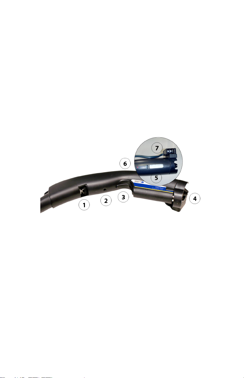
1.2 Air Gun Assembly ....................................................................................3
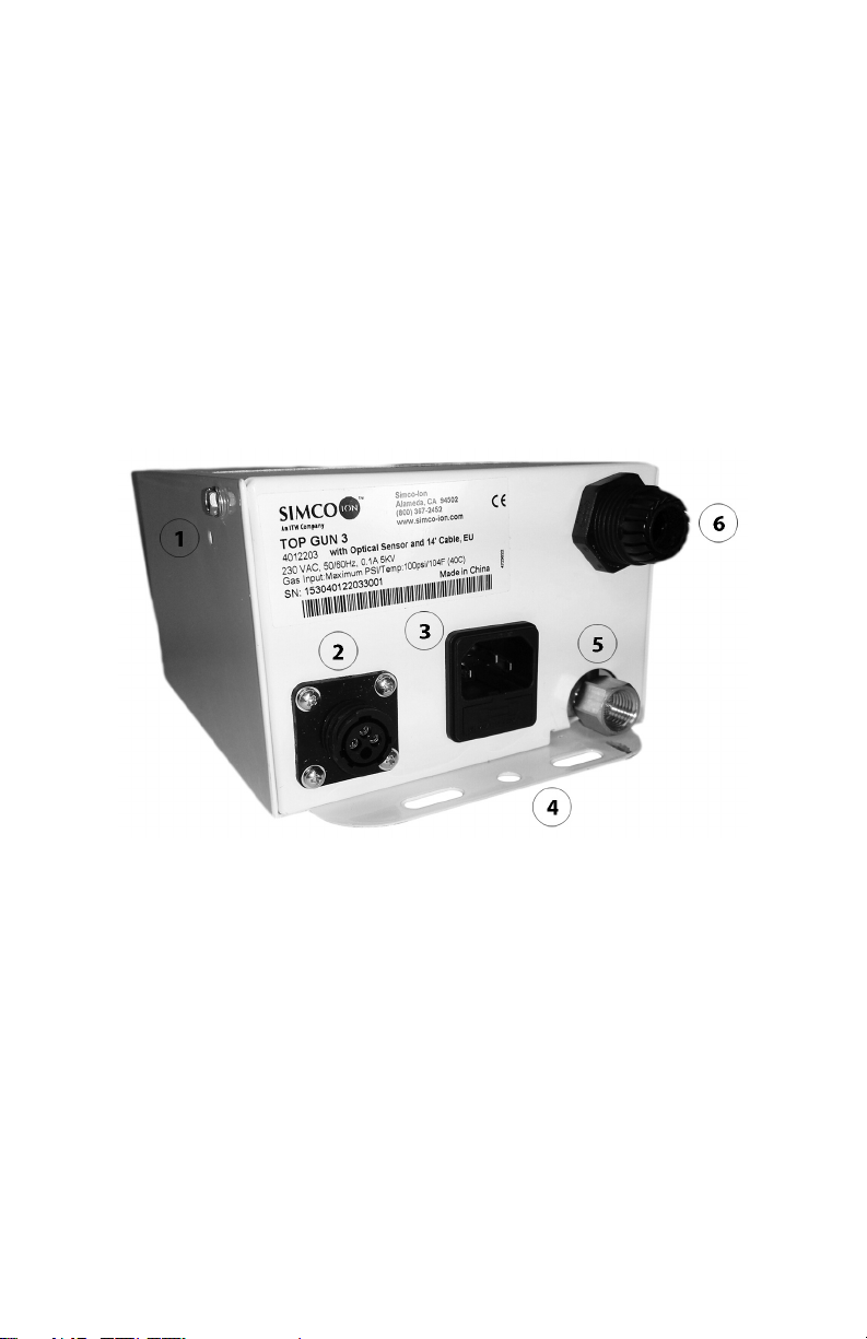
1.3 Power Unit Assembly...............................................................................5
2 Installation ........................................................................... 6
2.1 Mounting the Power Unit.......................................................................... 7
2.2 Connections.............................................................................................8
2.3 Mounting the Gun Hanger....................................................................... 8
2.4 Optional Remote Control Connection ......................................................9
2.5 Top Gun with Sidekick ...........................................................................10
3 Operation ........................................................................... 12
3.1 Performance ..........................................................................................13
3.2 Using Top Gun.......................................................................................14
3.3 Using the Sidekick Footswitch ...............................................................15
3.4 Using the Optional Optical Sensor.........................................................15
4 Maintenance ...................................................................... 16
4.1 Maintenance Requirements...................................................................17
4.2 Emitter Cleaning & Inspection ............................................................... 17
4.3 Filter-Nozzle Replacement..................................................................... 18
4.4 Balance & Ion Output Test.....................................................................20
4.5 Replacing the Electrical Safety Fuse .....................................................22
5 Specifications.................................................................... 23
5.1 Specifications.........................................................................................24
5.2 Parts & Accessories...............................................................................25
6 Warranty & Service .......................................................... 26

5101015-01 Rev 2 2
1.1 Top Gun Ionizing Air Gun
Simco-Ion’s Top Gun Ionizing Air Gun combines air ionization with
a forceful compressed air blast in a convenient hand held gun. Top
Gun provides the ability to clean and neutralize electrostatically
charged items; neutralizing the charges also prevents re-attraction
of the particulate. Top Gun also allows for neutralization of charges
that may damage static sensitive components by electrical
overstress or electrostatic discharge (EOS/ESD).
Figure 1. Top Gun Ionizing Air Gun with Sidekick

5101015-01 Rev 2 3
1.2 Air Gun Assembly
Simco-Ion’s Top Gun is an ionizing air gun that produces an intense
air flow rich in both positive and negative air ions. Directing the air
flow on an item that has a static electricity charge will neutralize the
charge and clean the item. It is ideal for cleaning items that have
developed a static charge due to handling or fabricating processes.
If the item has a negative static charge, it will draw positive ions from
the air flow. If the item has a positive static charge, it will draw
negative ions from the air flow. The air ions are attracted to the
oppositely charged item thereby neutralizing the static charge on
the item.
Figure 2. Top Gun Air Gun
1. Flow Control Knob
2. Ion Balance Adjustment
3. Trigger Switch
4. Ion Balance Reference Ring
5. Filter
6. Bi-Level LED
7. Optical Sensor (optional)
Top Gun uses low current, high voltage to energize an ionizing
cartridge located just beneath the filter-nozzle. In this position,
ionized air from the cartridge is routed into the air flow from the
nozzle. The transformer that provides power for the cartridge is
located in the power unit along with the solenoid and control circuit.
This makes the gun as light as possible. Ion balance is controlled by

5101015-01 Rev 2 4
a reference ring on the front of the ionizing cartridge. Adjustment of
ion balance can be accomplished at the gun.
Top Gun uses a light touch trigger for operation. Pressing the trigger
activates a control circuit which operates the air flow solenoid and
the low current, high voltage transformer, which are both located in
the power unit. A bi-level LED in the gun indicates stand-by/
operation status.

5101015-01 Rev 2 5
1.3 Power Unit Assembly
Top Gun can use clean dry compressed air, nitrogen or carbon
dioxide at pressures up to 100 psi. Compressed gas is connected
to a power unit that contains a solenoid to turn gas flow on and off.
High quality polyurethane tubing conducts the gas to the gun. At the
gun, flow is controlled from a whisper to a blast by an integral needle
valve using the gun control knob. The compressed gas is filtered
just prior to leaving the gun in an integrated, replaceable filter-
nozzle. The nozzle has been carefully designed to yield a forceful
blast while providing the lowest possible noise levels.
Figure 3. Top Gun Power Unit
1. Ion Balance Adjust
2. Remote Control/Footswitch/Optical Sensor Connector
3. Power Cord Connector with Fuse Drawer
4. Mounting Hole Flange
5. Compressed Air Connector
6. Top Gun Cable/Hose Connector

5101015-01 Rev 2 7
2.1 Mounting the Power Unit
The power unit can be mounted on any convenient surface such as
a wall or work bench leg using the mounting flanges. The rear
flanges have a mounting hole pattern that will match a variety of pre-
punched holes often found on work bench legs or perforated angle
stock. If mounted in a convenient location, with power and air
connections facing down, the power unit itself can be used as a
hanger for the blow-off gun cable. The front flange is designed to
retain the coiled gun cable.

5101015-01 Rev 2 8
2.2 Connections
Compressed Air Connection
Compressed air, nitrogen or carbon dioxide is supplied to the power
unit through a 1/4" NPT female connector. The connector contains
a screen to stop large debris from entering the unit. Do not remove
this connector. Support the connector with a wrench while installing
the user supplied compressed air fitting. Connect the compressed
air using appropriate tubing and fittings, the flow diameter of the
tubing and fittings should not be less then 3/16" (4 mm). If tubing or
fittings with inadequate flow diameter are used, performance will be
reduced. The compressed air must be clean, dry and oil free. The
maximum allowable input pressure is 100 psi (7 bar). Use of an
external pressure regulator and filter / dryer is recommended.
Power Connection
Top Gun accepts AC input of 120 VAC or 230 VAC 50/60 Hz single
phase. Top Gun must be grounded for safe and proper operation.
Top Gun is available with different line cords to meet the main
power connection plug requirements in many areas of the world.
Connect the supplied power cord to an appropriate 3-terminal
grounded AC power receptacle.
2.3 Mounting the Gun Hanger
The gun hanger can be mounted on any
convenient surface such as a wall, side of a table
top or work bench leg. The hanger can also be
mounted on the front of the power unit using the
pre-punched holes. Secure hanger with screws
and washers:
Figure 4. Top Gun Air
Gun Hanger

5101015-01 Rev 2 9
2.4 Optional Remote Control Connection
The power unit is equipped for remote actuation of airflow and
ionization. If remote actuation is required, the connection must be
done by qualified service personnel. Disconnect line voltage and
compressed air from power unit. Remove cover screws and open
chassis to expose power unit circuit board. Remove the knock-out
plug near the power and air connections. Install an appropriate
strain relief with cable or conduit. The remote control will actuate on
contact closure, the switch or relay must be rated for 100 volts DC
and be isolated from ground. Connect wiring from switch or relay to
the two 1/4" x 0.032" tabs on circuit board (J4 & J5) using insulated
quick disconnects. Close chassis and replace cover screws. Note:
the bi-level LED in the gun will remain at stand-by status when the
remote control is used.
CAUTION! ELECTRICAL SHOCK HAZARD
Conductors carrying AC power line voltage and high voltage
are exposed when covers are off and power is connected.
PRUDENCE! RISQUE DE CHOC ÉLECTRIQUE
Conducteurs transportant AC le courant secteur puissance et
haute tension sont exposés lorsque les couvertures sont
désactivées et la puissance est reliée.
CAUTION! ELECTRICAL SHOCK HAZARD!
Remote control circuit uses approximately 100 VDC.
PRUDENCE! RISQUE DE CHOC ÉLECTRIQUE
Circuit de commande à distance utilise environ 100 VDC.

5101015-01 Rev 2 10
2.5 Top Gun with Sidekick
If you ordered your Top Gun with Sidekick, then you have also
received the flexible semi-rigid neck stand we call Sidekick along
with a footswitch.
Figure 5. Top Gun Ionizing Air Gun with Sidekick
The Sidekick flexible stand may be mounted onto any flat benchtop
or wall surface. Position the nozzle at the desired location, typically
2" to 12" away from the object to be neutralized and cleaned.
Secure through the attached metal "U" base with a combination of
#8-32, or equal size, screw/ washer/ nut hardware (mounting
hardware is not provided). You can use the following dimensions as
a guide for mounting Sidekick to your surface. Screw holes should
be 1/8 inch diameter.

5101015-01 Rev 2 11
______________
Not to scale.
The nozzle and cable must be protected from impact with
moving machine components.
La buse et le câble doit être protégé des impacts avec
déplacement composants de la machine.

5101015-01 Rev 2 13
3.1 Performance
Top Gun reduces a static charge of ±1000 V down to 100V in less
than 1.3 second at a distance of six inches (15 cm) using 30-psi air
pressure. Discharge times vary upon air pressure used. Reference
the ESD Association ANSI/ESD Standard STM3.1-2006 for test
procedure. Balance is within ±15 V of zero at a distance of six
inches.

5101015-01 Rev 2 14
3.2 Using Top Gun
Hold the nozzle of Top Gun at the desired distance (typically 2 to 12
inches from object to be cleaned) and press trigger to activate air
flow and ionization. Use a back and forth motion to clean object, the
ionization will neutralize any static charges.
When the trigger is pressed, the LED on gun will increase in
intensity indicating operation of the electrical circuitry. The LED is
normally illuminated at a reduced intensity to indicate the gun is
ready for operation.
The air flow can be set as desired using the flow
control knob in the gun handle. With full pressure
applied to the power unit, the flow can be
controlled from a whisper to a blast with the flow
control knob.
The Optical Sensor (OS) version comes preset
for maximum airflow; the Flow Control Knob is
disabled by a locknut. It is not possible to
increase or decrease the air flow in “OS” version.
This gun complies with the Occupational Safety and Health Act
(OSHA), 29 CFR ch. XVII, Part 1910.242B, entitled "Compressed
air used for cleaning". This part reads "Compressed air shall
not be used for cleaning purposes except where reduced to
less then 30 psi and then only with effective chip guarding and
personal protective equipment". The gun complies with the air
pressure limit through pressure relief slots in the nozzle;
however, effective chip guarding and personnel protective
equipment must be provided by the user.
Occupational Safety and Health Act (OSHA), 29 CFR ch. XVII, Part
1910.95, entitled “Occupational noise exposure” specifies a
maximum permissible noise exposure of 3 hours per day at 97 dB.
At maximum pressure the gun produces a noise level of 97 dB;
therefore, wear hearing protectors if the Top Gun is operated
continuously for more than three hours per day.

5101015-01 Rev 2 15
3.3 Using the Sidekick Footswitch
If you have ordered Top Gun with Sidekick, then you have also
received the footswitch. The switch connects to the power supply
and when depressed, activates both airflow and power to the ion
emitter assembly. A red LED on the nozzle indicates power.
3.4 Using the Optional Optical Sensor
For automated assembly operation, Top Gun may be ordered with
an infrared Optical Sensor. The Optical Sensor automatically
activates Top Gun when an object is in range. The Optical Sensor
has an "adjustable range" from 1-30 inches.
Plug the sensor cable into the power unit (if not already done so out
of the shipping carton). To use the Optical Sensor, simply pass or
hold an object to be ionized in front of Top Gun. Top Gun (orange
LED is lit) will trigger and stay on until the object is removed from in
front of the sensor. The green LED is lit when the optical sensor is
on. The lower dial should be set to the "L" position (on the Light
reflection). This triggers Top Gun when an object passes in front of
the sensor. If the lower dial is set to the "D" position (for Dark), then
the sensor will trigger Top Gun (orange LED is lit) if the object is
removed in front of the nozzle. If desired, the top dial may be
adjusted to change the sensitivity of the sensor (min to max).
Figure 6. Top Gun with Optical Sensor
This manual suits for next models
3
Table of contents
Other ITW Power Tools manuals
Popular Power Tools manuals by other brands

Makita
Makita LXT DSC163 Series instruction manual

Makita
Makita 4350FCT Parts Breakdown

RODCRAFT
RODCRAFT RC6605RE Operator's manual

Krais
Krais P&P K50-400 Manual instruction

Makita
Makita HM1100C Parts Breakdown

AXXIOM Manufacturing, Inc.
AXXIOM Manufacturing, Inc. SCHMIDT 120 Operation and maintenance manual