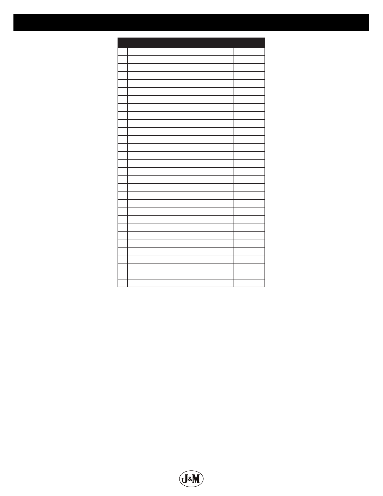
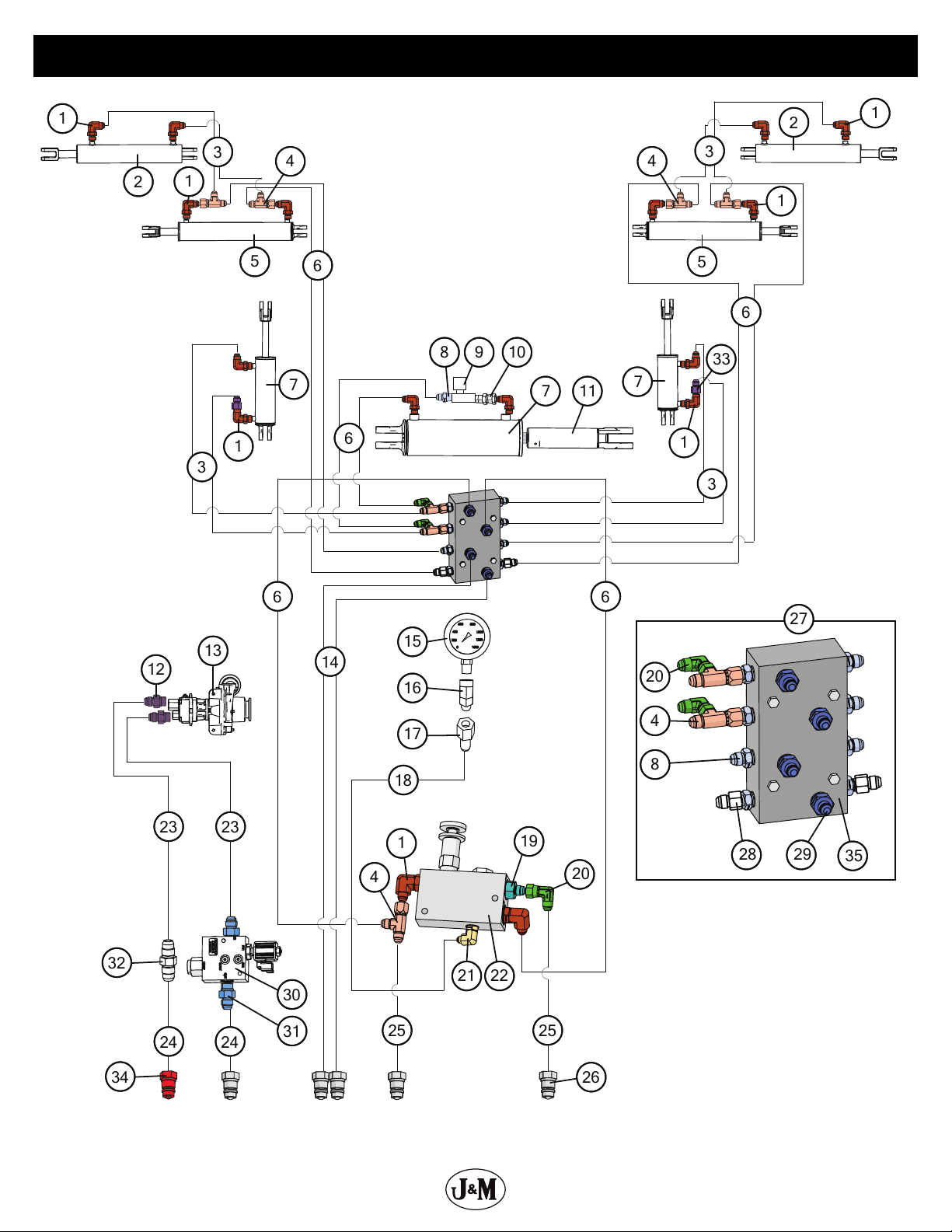
J&M Nitro Gro 5010 User manual

J&M Manufacturing Co, Inc
284 Railroad Street - P.O. Box 547 | Fort Recovery, OH 45846 | Ph: (419) 375-2376 | Fax: (419) 375-2708
www.jm-inc.com
ASSEMBLY MANUAL MODEL
Manual
Rev. 4.12.2021

2
1
234
5
7
9
10
11
12
13
14 15 16
17
18
19
20
2
1
8
7
21 22
23
24
25
26 27
2
6
Decals

3
# Description: Decals Part. No.
1 Grease Decal JM0015104
2 Warning - Pinch Point JM0014994
3 Down Pressure Decal JM0035892
4 Warning - Insert Pin Before Road Transport JM0038103
5 Danger - Electrocution Hazard JM0035887
6 Caution - Observe Instructions JM0035881
7 Danger - Crushing Hazard JM0035883
8 J&M Oval JM0038110
9 Warning - Towing Stability JM0035882
10 Warning - High Pressure Fluid JM0035880
11 NitroGro with J&M Decal JM0039474
12 Open Tank Maintenance Valve JM0039478
13 Close Tank Fill Valve JM0035891
14 Open Agitation Valve JM0039479
15 Check Filter Daily JM0035884
16 Ground Drive Adjustment JM0038102
17 Ground Drive Tire Pressure JM0038101
18 2.0 x 9.0 Red Reective Strip JM0009945
19 2.0 x 9.0 Fluorescent Orange Strip JM0009944
20 Nitrogro Logo5010L JM0038114
20 Nitrogro Logo5010R JM0038116
20 Nitrogro Logo5016L JM0038117
20 Nitrogro Logo5016R JM0038118
21 NitroGro Decal JM0039473
22 J&M Website JM0038108
23 2.0 x 9.0 Reective Amber Strip JM0009946
24 Jack Handle Storage JM0038105
25 Warning - Cylinder Stops JM0035890
26 Check Tire Pressure JM0038097
27 Tighten Lug Nuts JM0035885
Decals

4
Hydraulic Schematic
3
3
3
3
6
6
6
6
25
25
14
6
23
23
18
7
5
1
2
2
5
7
7
11
33
24
24
32
31
30
To Inlet
Hydraulic Pump
To Outlet
4”x8”
Raise/Lower
0-1500 PSI
Pressure
Gauge
4” x 24”
Fold/Unfold
Inside
4” x 24”
Fold/Unfold
Inside
3-1/2” x 14”
Fold/Unfold
Outside
3-1/2” x 14”
Fold/Unfold
Outside
4”x8”
Raise/Lower
4”x8” Down
Pressure
4
4
1
9
8
1
1
20
4
8
27
28
29
4
1
19
21
22
20
Manifold
17
16
15
1
1
10
13
12
26
34
35

5
Hydraulic Schematic
Description Part No.
1 3/8”Male JIC x 1/2” Male ORB; 90 Degree Elbow JM0037159
2 3-1/2”x 14”Welded Non-Cushion JD Cylinder JM0055022
2 Seal Kit for 3-1/2”x 14” Hydraulic Cylinder (JD-629) JM0074483
3 3/8”x 108” Hydraulic Hose 108inch6M3K-6G-6FJX-6G-6FJX JM0041615
4 3/8”Male JIC x 3/8” Female JIC Swivel x 3/8” Male JIC; Tee JM0037163
5 4”Bore, 24”Stroke Welded Hydraulic Cylinder - Heavier Clevises JM0030730
5 Seal Kit for 4”x 24” Hydraulic Cylinder (JD-609) JM0039242
6 3/8”x 84” Hydraulic Hose 84inch6M3K-6G-6FJX-6G-6FJX JM0041613
7 4”Bore, 8”Stroke Welded Hydraulic Cylinder - Heavier Clevises JM0030757
7 Seal Kit for 4”x 8” Hydraulic Cylinder (JD-608) JM0039241
8 3/8”Male JIC x 3/8”Male NPT; Straight JM0037167
9 Parker Flow Control Valve (NitroGro) JM0041626
10 3/8”Male NPT x 3/8” Female JIC Swivel JM0073350
11 Shaft for Down Pressure Cylinder (NitroGro) JM0032428
12 1/2”Male JIC x 5/8” Male O-Ring; Straight JM0010294
13 FMCSC-155F-HYD-206 - Ace Pump JM0061538
13 Ace 155 Pump Hydraulic Side Replacement Seal Kit - RK-BAC-75-HYD-L JM0061310
14 3/8”x 165” Hydraulic Hose 165inch6M3K-6G-6FJX-6G-8MP JM0041612
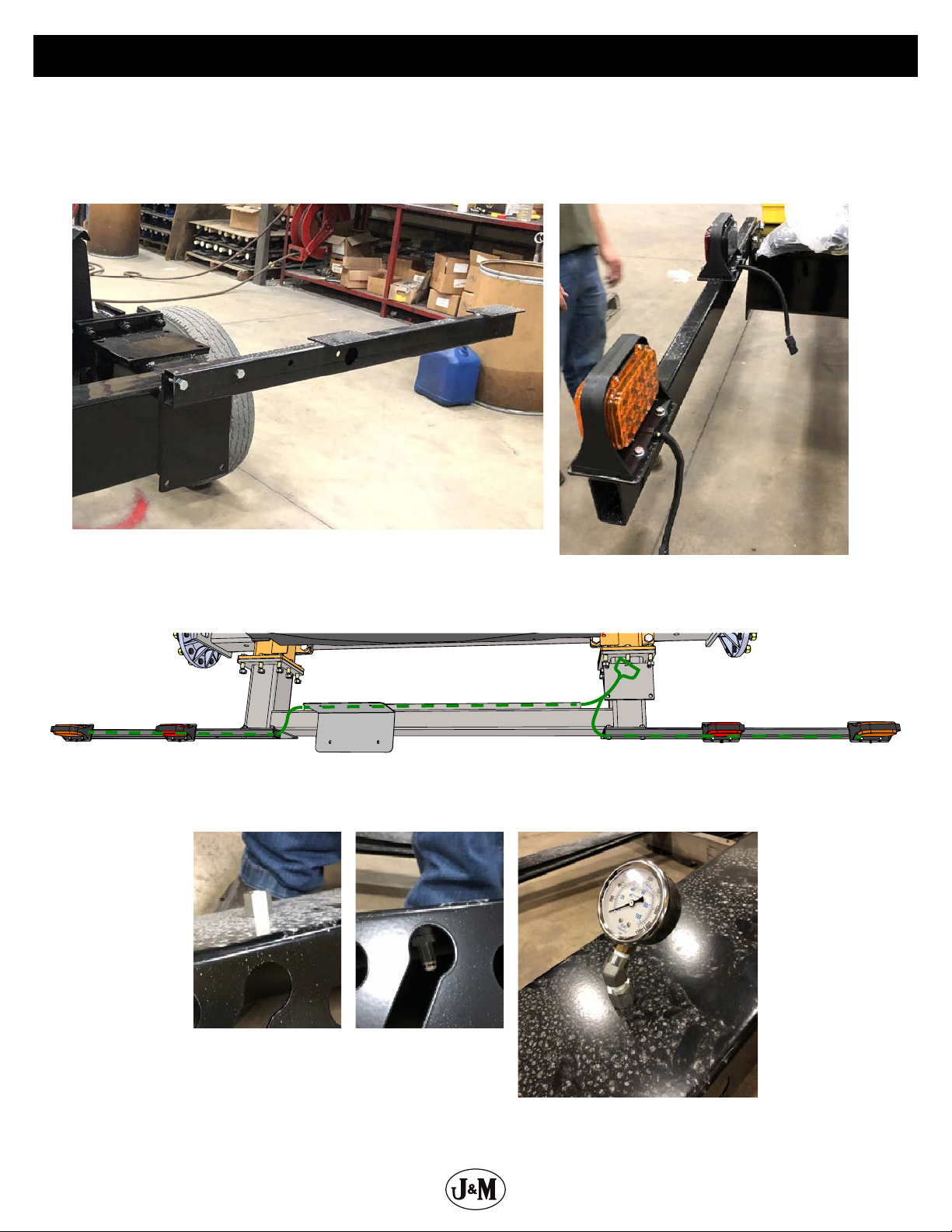
15 Pressure Gauge 0-1500psi (NitroGro) JM0037152
16 1/4”Male NPT x 1/4” Female NPT Rigid; 45 Degree Elbow JM0037156
17 1/4”Female NPT x 3/8” Male JIC Compression Bulk Head Fitting JM0037155
18 3/8”x 29-1/2” Hydraulic Hose 29.5inch6M3K-6G-6FJX-6G-6FJX90S JM0041687
19 3/8”Male JIC x 1/2” Male ORB; Straight JM0010302
20 3/8”Male JIC x 3/8” Female JIC Swivel; 90 Degree Elbow JM0010295
21 3/8”Male JIC x 3/8” Male ORB; 90 Degree Elbow JM0026121
22 Down Pressure Relief Valve JM0034806
23 1/2”x 180” Hydraulic Hose 180inch8M3K-8G-8FJX-8G-8FJX JM0073123
24 1/2”x 168” Hydraulic Hose 168inch8M3K-8G-8MP-8G-8FJX JM0073122
25 3/8”x 84” Hydraulic Hose 84inch6M3K-6G-6FJX-6G-8MP JM0054708
26 1/2”Female NPT x Male Pioneer - Low Flow, Ball Style JM0039220
27 5000 Applicator Manifold Block ASM JM0073299
28 3/8”Male JIC x 3/8” Female JIC with .062 Orice JM0047738
29 3/8”Male JIC x 1/2” Male NPT; Straight JM0037172
30 Hydraulic PWM Control Valve for Nitrogen Fertilizer Pump (F14264A1) JM0059223
31 1/2”Male JIC x 1/2” Male O-ring; Straight JM0010293
32 1/2”Male JIC x 1/2” Male JIC; Straight JM0041452
33 3/8”Male JIC x 3/8” Female JIC with .094 Orice JM0047735
34 1/2”Female NPT x Male Pioneer - High Flow, Cone Style JM0018254
35 Main Manifold Block (NitroGro) JM0028902

6
1. Bolt on the back frame to the right leg (JM0058704) and left leg (JM0058706) of the frame with (14) 3/4” x
2-1/2” bolts and (14) 3/4” centerlock hex nuts.
2. Bolt on axle (JM0058314) with (8) 1” x 3” bolts and (8) 1” centerlock hex nuts.
3. Set the frame up on blocks. Use a tape measure to ensure the back corner of the applicator frame is
approximately 30” o the ground.
5016
5010
Frame
4. Mount tongue (JM0058707) to the right and left leg
frames with (20) 3/4”-10 x 2-1/2”Gr5 Z Hex Bolt and
(20) 3/4”-10 Gr2 Z Centerlock Hex Nut.
5. Mount hydraulic valve block with (4) 1/4”x 2-1/2”
bolts and (4) 1/4” serrated ange hex nut.
6. Connect hoses into valve bank and route them
through the D-ring. The image below is showing the
part numbers of the hoses that connect to each
tting on the valve bank.
JM0041613 JM0041613
JM0041613
JM0041615
JM0041615
JM0041612

7
7. Connect the corresponding hoses to the ttings as shown in the previous steps and drape them as shown in
the images below.
8. Mount the tank saddles (JM0036718) 3 for 5010 models and 5 for the 5016 models. On the rear of the saddles
there are two sets of holes. One set of holes has two holes and one has three holes. Place the saddle on the
frame so the set with two holes is towards the passenger side of the applicator. Mount the rear tank saddle
rst. The rear and middle tank saddles are fastened using the back set of holes for 5010, and front set of holes
for a 5016. Fasten with (4) 3/8”-16 x 1” Gr5 Z SF Hex Bolt and (4) 3/8”-16 Gr5 Z SF Hex Nut on each tank saddle.
5010
5016
Frame

8
9. Bolt on light bars (JM0036071) using (2) 1/2” x 2-1/4”bolts and (2) 1/2”centerlock hex nut. Use the outside
holes in the frame when mounting the light bars.
10. Secure rear lights onto the light bars (JM0036071) with (4) 1/4” x 1”bolts and (4) 1/4”serrated ange nuts for
each light. Red lights face out from the applicator and are located closer to the inside of the applicator while
yellow lights are located closer to the outside.
11. Guide the rear light harness through the conduit on the inside of the rear applicator frame. Guide the end of
wire harness that is labeled“Left” through the conduit towards the left (driver’s side) light bar. Push the end of
the harness that is labeled “Right” through the light bar on the right (passenger’s) side.
12. Prep the front hydraulic hose guard (JM0034836) by attaching the pressure gauge (JM0037152) with 1/4” Male
NPT x 1/4” Female NPT Rigid; 45 Degree Elbow (JM0037156) and 1/4” Female NPT x 3/8”Male JIC Compression
Bulk Head Fitting (JM0037155).
Frame

9
13. Use (2) 3/8”x 4” bolts, (2) 2”plastic spacers (JM0002444), and (2) 3/8” serrated ange nuts to fasten down
pressure relief valve bank (JM0034806) to the front hydraulic hose guard. Connect hose (JM0041687) from
pressure gauge to down pressure relief valve bank.
14. Run the (2) 1/2” x 168” hoses (JM0073122) up the tongue and connect one to the PWM control valve
(JM0059223) and one to a 1/2” Male JIC x 1/2” Male JIC; Straight tting (JM0041452). On the other side of the
tting and the PWM valve connect (2) 1/2”x 180”hoses (JM0073123)and run it from the top of the tongue
along the frame of the applicator all the way to the hydraulic pump on the right/passenger side. Later in this
process, these hoses will connect to the pump. Mount the front hose guard using (4) 3/8”x 1”serrated ange
bolts and (4) 3/8” serrated ange nuts. Mount the PWM valve to the top and inside of the tongue shroud using
(2) 5/16”-18 x 2-1/2” Gr5 Z Hex Bolts and (2) 5/16”-18 Gr5 Z SF Hex Nuts as shown in the image below.
Frame

10
15. Connect the hoses from the valve bank on top of the frame to the down pressure relief valve bank on the
middle of the tongue. Connect (2) 3/8”x 84” hoses from the down pressure relief valve bank and drape the
hose past the front of the tongue. Attach the high ow poineer coupler (JM0018254) to the hose that goes to
the hydraulic motor but not to the PWM valve, then attach (5) low ow pioneer couplers (JM0039220) to the
rest of the hoses draped in front of the tongue. Please look to the beginning of this manual to reference where
hydraulic hoses should connect.
Frame
1. Holes are predrilled in the tank for the ttings. Add ttings in the two holes in the back of the tank, one 3/4”
NPT Bulkhead Tank Flange Assembly (JM0035222) and one 1-1/2” Poly Bulkhead Tank Fitting with EPDM
Gasket (JM0061522). Then one 3/4” NPT Bulkhead Tank Flange Assembly (JM0035222) for the hole in the front.
The rubber o-ring on the tting goes inside the tank and the nut will screw on from the outside. These are
left-handed thread ttings. Then use a 1-1/2”Male Thread x 1-1/2”90 deg Hose Barb (JM0061527) and (2) 3/4”
Hose Barb x 3/4” Male NPT; 90 Deg (JM0035226) respectively.
Tank

11
2. Place the tank on the saddles by using an overhead hoist. The lid should be positioned to the back of the
applicator.
3. Measure the back of the tank from the frame to the seam at the center of the tank. Center the tank so the
distance measures about 25”on each side (as shown below).
Seam
~25”~25”
Tank

12
4. Fasten the tank to the saddles using the (3) or (5) tank straps (JM0030208) depending on whether you have a
5010 or 5016. The tank straps use (4) 1/2”x 4-1/2”fully threaded bolts and (4) centerlock nuts per strap.
5. Zip tie each circut of hoses together. Attach hydraulic hose holder to frame. Hook all hydraulic hoses through
the hydraulic hose holder on the tongue shroud.
Tank

13
6. Attach jack mounting bracket (JM0031545) to the mounting plate which is welded on the underside of the
frame using a 1”x 6” bolt and 1” centerlock hex nut.
7. Using a fork lift or overhead hoist, lift the front end of the applicator o the ground enough to align the four
holes on the jack (JM0030054) with the four holes on the mounting bracket. Secure the jack to the mounting
bracket with (4) 5/8”x 2” Gr8 hex bolts and (4) 5/8” centerlock hex nuts. Tighten the bolts and keep the jack in
place using the 3/4”L-pin for mounting plate centerlock pin for top of the jack.
8. Run the 1-1/2” x 180” (JM0040330) hose for 5010 applicator or 1-1/2”x 228”(JM0040211) for the 5016
applicator from the back to the front of the applicator. Let it sit loose for the next couple of steps on the
passenger side.
9. Attach pump mounting bracket (JM0034960) using (2) 3/8”x 1” serrated ange bolts and (2) 3/8”serrated
ange nuts. Attach pump using (2) 3/8”x 1-1/2”bolts and (2) 3/8” serrated ange nuts on rear tank saddle
front plate.
Tank

14
10. Add the manifold ttings as shown in the image below.
Tank
1
2
4
3
11
5
9
10
8
12
7
1716
6
14 15
19
18
13
20
21
Description Part No.
1 3/4”Hose Clamp SS JM0039205
2 M100 Manifold Flange x 3/4” Hose Barb; Straight JM0021401
3 Manifold Flange Clamp for M100 Fittings JM0032496
4 Manifold Gasket for M100 Fittings with Rib JM0035239
5 Ball Valve with M100 Manifold Flange JM0033824
6 Hose Clamp - 1-13/16”Min, 2-1/16” Max JM0021189
7 2”Manifold Flange x 90 Deg 1-1/2”Hose Barb JM0034352
8 M200 Manifold Flange x M200 Manifold Flange x M100 Manifold Flange; Tee JM0035116
9 Manifold Gasket for M200 Fittings JM0021145
10 Manifold Flange Clamp for M200 Fittings JM0035251
11 90° Coupling - 2”Manifold Flange JM0033991
12 Manifold Y Strainer - M200 Manifold Flange, 30 Mesh JM0033803
13 FMCSC-155F-HYD-206 - Ace Pump JM0061538
14 Manifold Gasket for M220 Fittings JM0035278
15 Manifold Flange Clamp for M220 JM0035238
16 2”Hose Barb x M220 Manifold Flange; Straight JM0033796
17 T-Bolt Hose Clamp 2”Hose, 2-5/16”Min OD JM0035247
18 3/8”-16 Gr5 Z SF Hex Nut JM0002152
19 3/8”-16 x 1”Gr5 Z SF Hex Bolt JM0002092
20 Plate - Hydraulic Fertilizer Pump Mounting (5000) JM0034960
21 3/8”-16 x 1-1/2”Gr5 Z SF Hex Bolt JM0001633
22 Ace 155 Pump Hydraulic Side Replacement Seal Kit - RK-BAC-75-HYD-L JM0061310
23 Ace 155 Pump Water Side Replacement Seal Kit - RK-FMCSC-150 JM0061308
22
23

15
11. Connect hydraulic hoses to the small pump. The hose that is coming from the PWM vlave will plug into the
inlet opening of the motor, while the other hose connects to another hose that goes to the high ow pioneer
These hoses will connect to the outlet tting on the motor. There will be markings (arrows and I for inlet and O
for outlet) as to which one is inlet vs outlet on the hydraulic motor itself. This step is CRITICAL, please reference
the hydraulic schematic.
12. Attach 1-1/2”pressure hose and tighten clamp (JM0021189) (use lubricant to slip hose on tting). Pull hose
tight through D-rings to the front of the applicator.
13. Attach the hitch as well as the safety chain and hose holder bracket using the hardware shown in the images
below.
Description Part No.
1 30k LB Safety Chain Set (2 Chains) JM0027440
2 NitroGro Applicator Safety Chain Spacer JM0059128
3 3/4”-10 x 6”Gr8 Z Hex Bolt JM0037185
4 3/8”-16 x 3/4”Gr5 Z Hex Bolt JM0001663
5 1/2”Hose Holder Rod (12HHR) JM0027120
6 CTD Perfect Hitch Base PP23XLR JM0037174
7 CTD Perfect Hitch Clevis 1-1/4”x 1-3/4” Slot JM0037173
8 3/4”-10 Gr2 Z Centerlock Hex Nut JM0002147
9 3/4”USS Z Flat Washer JM0010006
10 CTD Perfect Hitch Assembly (NitroGro) (Includes Bolt & Nut) JM0037177
3
8
2
4
7
5
6
1
9
10
Tank

16
14. Assemble the ow control monitor and manifold parts. Be sure to install a gasket between each connection
point of the manifold. Then attach ow control mount using (4) 3/8” x 1” serrated ange bolts and (4) 3/8”
serrated ange nuts.
15. Connect the 1-1/2” pressure hose to the Raven control valve as shown and tighten clamp (JM0021189).
Connect wire harness that comes with Raven control (JM0055255).
Description Part No.
1 M100 Manifold Flange x 3/4” Hose Barb; 90 Degree JM0032501
2 3/4”Hose Clamp SS JM0039205
3 Mount For Control Valves and Flow Monitors - 5000 Universal JM0077615
4 Raven Flow Meter RFM60P JM0032488
5 Manifold Flange Clamp for M100 Fittings JM0032496
6 Manifold Gasket for M100 Fittings with Rib JM0035239
7 Manifold Flange Clamp for M200 Fittings JM0035251
8 Manifold Plug for M200 Fittings with 1/4”NPT for Gauge JM0021147
9 Pressure Gauge Stainless Steel 0-100psi, 1/4”NPT JM0036636
10 1/4”Male NPT x 1/4” Female NPT; 90 Degree Elbow JM0020115
11 5000 Series Sun Shield JM0077626
12 5000 Series Lower Sun Shield JM0077633
13 Raven Boom Valve JM0032478
14 M200 Manifold Flange x M200 Manifold Flange x M100 Manifold Flange; Tee JM0035116
15 3/8”-16 x 2-1/2”x 5-1/4” Round U-Bolt JM0018627
16 3/8”-16 Gr5 Z SF Hex Nut JM0002152
17 3/8”-16 x 1”Gr5 Z SF Hex Bolt JM0002092
18 Manifold Gasket for M200 Fittings JM0021145
19 2”Manifold Flange x 90 Deg 1-1/2”Hose Barb JM0034352
20 Hose Clamp - 1-13/16”Min, 2-1/16” Max JM0021189
21 100psi Spike Valve with M100 Manifold Flanges JM0032499
22 1/4”-20 x 1/2”Gr5 Z Hex Bolt JM0001481
22
10
568
7
12
9
3
12
11
21
4
13
14
18 15
17
19
20
16
Tank
Shaded cells make up
an assembly JM0032484
(3 of item 7, 3 of item
8, 1 of item 13, and 1of
item 18)

17
Tank
16. Below are the parts for our ow monitors and the hardware used to connect them to the mount.
17. Assemble the ll and sump manifold ttings then attach them to the locations shown in the following steps.
Assembly for a 2”ll setup.
12 13 814 9765
Description Part No.
1 1/2”-13 Gr2 Z Centerlock Hex Nut JM0001511
2 1/2”-13 x 1”Gr5 Z Hex Bolt JM0010225
3 Mounting Plate - 2” Ball Valve (NitroGro) JM0034889
4 Cable Lanyard JM0039282
5 T-Bolt Hose Clamp 2”Hose, 2-5/16”Min OD JM0035247
6 2”Hose Barb x M220 Manifold Flange; Straight JM0033796
7 Manifold Flange Clamp for M220 JM0035238
8 2”Full Port Flange Ball Valve JM0031370
9 Manifold Gasket for M220 Fittings JM0035278
10 2”Full Port Manifold x 2” Male QDC JM0035249
11 2”QD Cap (NitroGro) JM0035250
12 2”Male MPT X 2” Full Port Manifold Flange JM0033793
13 90 Degree Coupling - 2” Full Port Manifold Flange JM0033795
14 2”Full Port Manifold Tee - 220 Series JM0033797
3
5 6
4
7 8 9
1 2
10 11
14
13
15
16
11
6
5
9
10
4
8
3
7
2
1
12
18 19 20
17
Description Part No.
1 Green Polyurethane Ball for Wilger Flow Indicator JM0055003
2 Red Polyurethane Ball for Wilger Flow Indicator JM0055004
3 Red Glass Ball for Wilger Flow Indicator JM0055005
4 1/2” SS Ball for Wilger Flow Indicator JM0055006
5 7/16” Stainless Steel Ball for Wilger Flow Indicator JM0061580
6 Cap with O-Ring - Wilger Flow Indicator JM0021579
7 3/8” Hose Barb with O-Ring; 90 Degree JM0024469
8 O-Ring Seal for Wilger Flow Monitor JM0055001
9 Ball Retainer for Wilger Flow Monitor JM0055002
10 U-Clip for Wilger Flow Monitor JM0055000
11 Wilger Flow Indicator JM0021569
12 3/8”Hose Clamp SS JM0039206
13 1/4”-20 Gr5 Z SF Hex Nut JM0001630
14 3/4”Hose Clamp SS JM0039205
15 3/4”Hose Barb with O-Ring; 90 Degree JM0024468
16 1/4”-20 x 2”Gr5 Z Hex Bolt JM0001591
17 Wilger Flow Indicator Manifold - 6 Row with 3/4”Inlet and 3/8” Outlets JM0024470
18 Wilger Flow Indicator Manifold - 5 Row with 3/4”Inlet and 3/8” Outlets JM0021591
19 Wilger Flow Indicator Manifold - 4 Row with 3/4”Inlet and 3/8” Outlets JM0039279
20 Wilger Flow Indicator Manifold - 3 Row with 3/4”Inlet and 3/8” Outlets JM0039280

18
Assembly for a 3”ll setup.
18. Connect tank shut o valve to the tting at the bottom of the tank and tighten clamp. Ensure that the gasket is
centered when connecting. Should be angled towards the ll valve.
4 5 6
3
7 98 10
12
11
16
12
14 15
813 9654
Description Part No.
1 1/2”-13 Gr2 Z Centerlock Hex Nut JM0001511
2 1/2”-13 x 1”Gr5 Z Hex Bolt JM0010225
3 Cable Lanyard (NitroGro) JM0039282
4 T-Bolt Hose Clamp 3”Hose, 3-5/16”Min OD JM0035248
5 3”Manifold Flange x 3”Hose Barb JM0021244
6 Manifold Flange Clamp for M300 Fittings JM0035237
7 Ball Valve Mount Plate 3”Banjo (NitroGro) JM0034894
8 Ball Valve - 3” Full Port Flange Manifold JM0021230
9 Manifold Gasket for M300 Fittings with Rib JM0021239
10 3”Manifold Flange x 3”QDC Male JM0035205
11 3”Poly Cam Lever Cap JM0035206
12 3”MNF x 3” FNPT Tank Fitting BTM DRN JM0035114
13 3” Manifold Tee JM0021232
14 M300 Manifold Flange x M300 Manifold Flange; 90 Degree JM0033979
15 3”Manifold Flange x 2”Hose Barb JM0034333
16 T-Bolt Hose Clamp 2”Hose, 2-5/16”Min OD JM0035247
Tank

19
19. Mount the ball valve to the mount plate to rear driver’s side of applicator using (2)1/2”x 1-3/4”hex bolts and
(2) 1/2” centerlock hex nuts. A wire hangs on the cap of the valve. Before fastening the bolts with the nuts,
loop one eyelet of the wires over the bolt between the plate and the frame (as shown below).
20. Connect tank shut o valve to ll valve with 2” x 36” hose (JM0040215) for 5010 applicators and 3”x 38”hose
(JM0040216) for 5016 applicators. Connect tank shut o valve to the pump using 2”x 32” hose (JM0040224).
Tighten all four clamps (JM0035247).
Tank

20
21. Attach 3/4”x 55”hose (JM0040332) from top front of tank to banjo relief valve on Raven control and tighten
clamps (JM0039205).
22. Attach water tank (JM0030587) with (4) 5/16”-18 x 1/2” Gr5 Z Hex Bolts. Use plastic thread dope for spout
attachment and plugs.
23. Attach manual canister (JM0010115) to rear driver’s side of applicator using (3) 1/4”- 3/4”bolts, (3) 1/4”USS at
washers and (3) 1/4”serrated ange hex nuts.
4
1235
13
Description Part No.
1 1/4”-20 Gr5 Z SF Hex Nut JM0001630
2 1/4” ID, 3/4”OD Z Flat Washer JM0003090
3 1/4”-20 x 3/4” Gr5 Z Hex Bolt JM0001507
4 Operator’s Manual Canister JM0010115
5 Slow Moving Vehicle Sign JM0001616
Tank
Other manuals for Nitro Gro 5010
1
This manual suits for next models
1
Table of contents
Other J&M Farm Equipment manuals

J&M
J&M X2431 User manual

J&M
J&M SpeedTender LC290 User manual

J&M
J&M 206270 User manual

J&M
J&M Speed Tender 535-ST User manual

J&M
J&M Nitro Gro 5010 User manual

J&M
J&M 375ST Speed Tender User manual

J&M
J&M GC31t-1 User manual

J&M
J&M 32 Series User manual

J&M
J&M SpeedTender 500ST User manual

J&M
J&M NITRO-GRO 5010 User manual