J&M 525 User guide

J&M Manufacturing Co, Inc
284 Railroad Street - P.O. Box 547 | Fort Recovery, OH 45846 | Ph: (419) 375-2376 | Fax: (419) 375-2708
www.jm-inc.com
Rev. 11.13.2018
Roll Tarp
SETUP MANUAL
ALL MODELS
Grain Cart

2
Table of Contents
Manual Roll Tarp
3...............................................................................Endcap Assembly
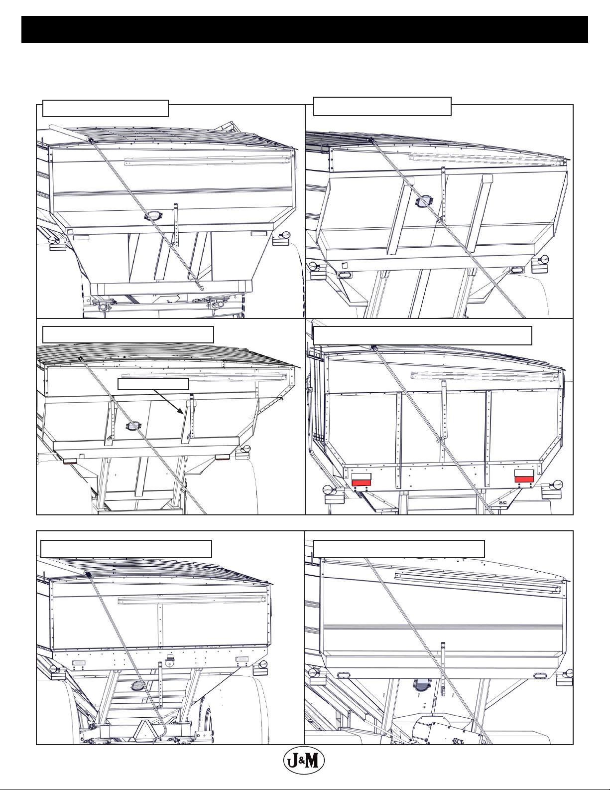
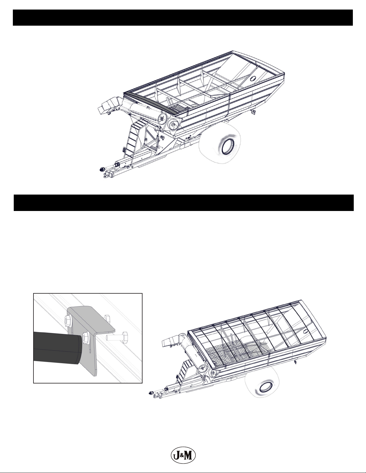
4....................................................................... Hanger Bracket Locations
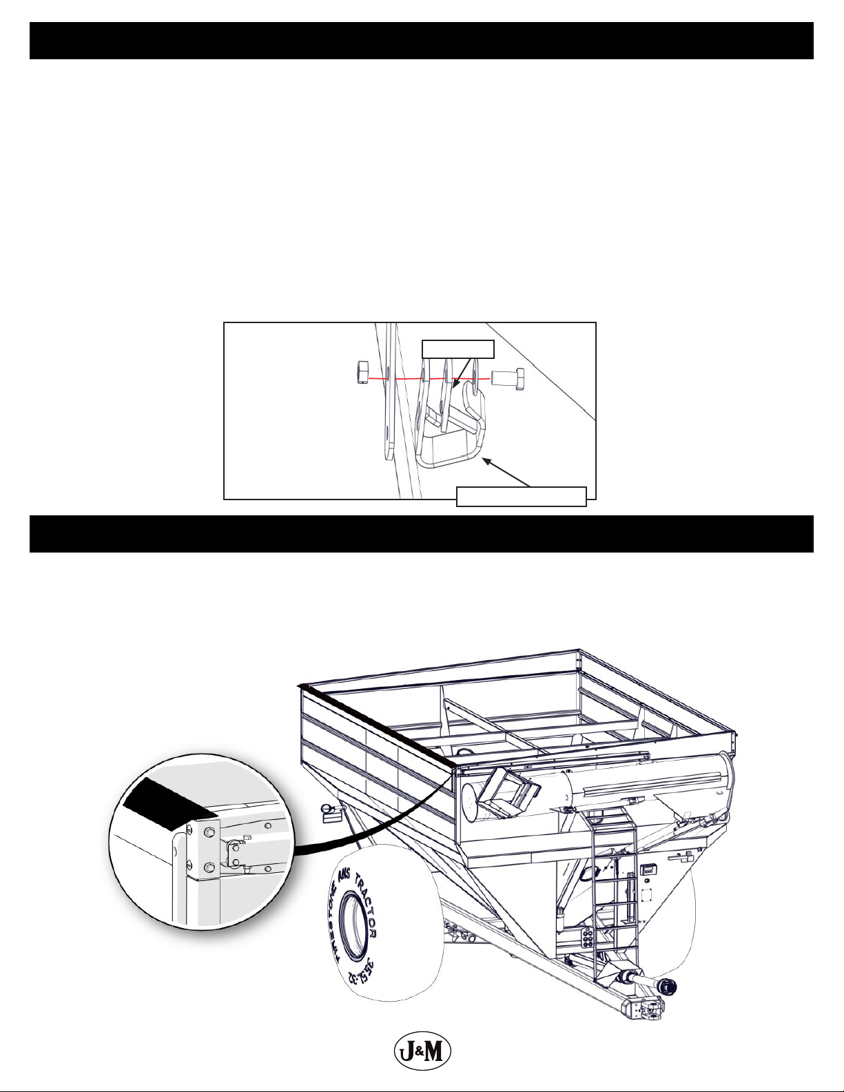
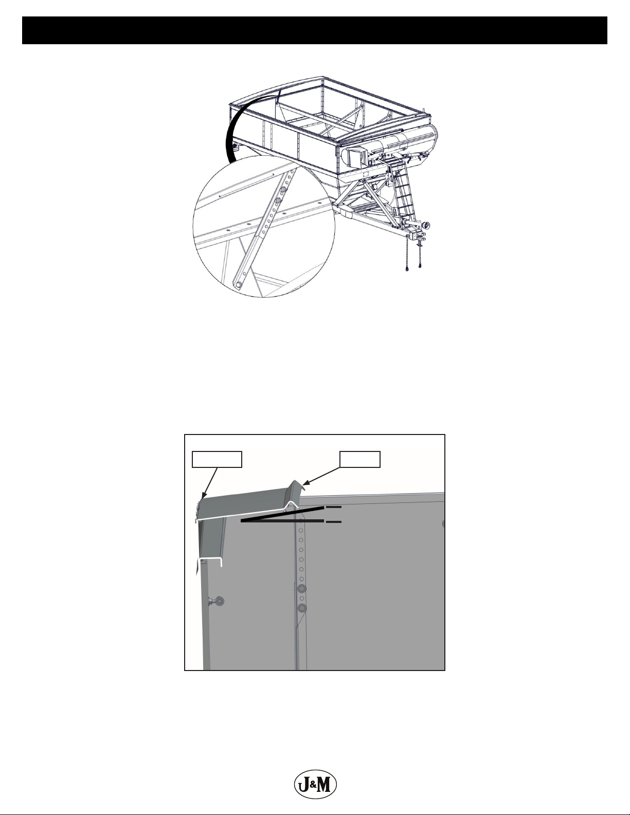
5....................................................................... Hanger Bracket Assembly
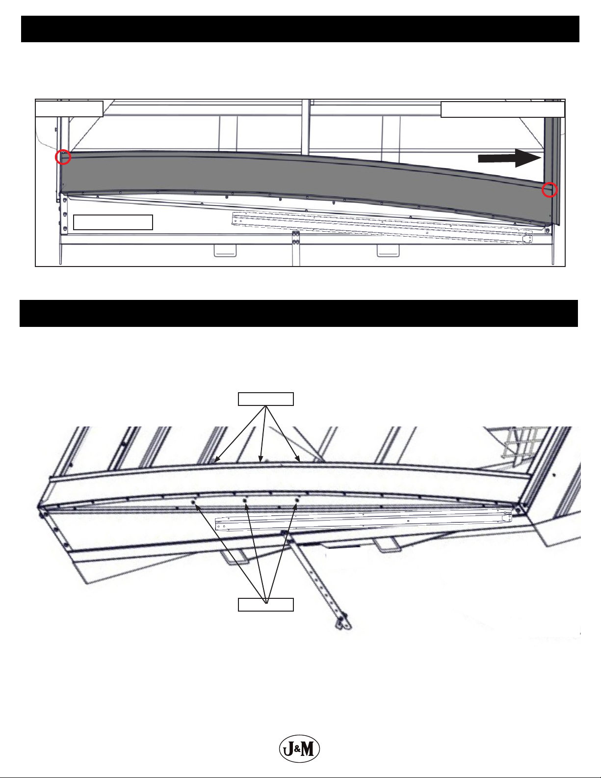
5..................................................................................Tightening Lip
6...........................................................................Installing Rear Endcap
7.....................................................................Rear Endcap Support Braces
8.........................................................................Tightening Rear Endcap
8................................................................................ Installing J-Bolts
9..........................................................................Installing Front Endcap
9.......................................................................................Tarp Bows
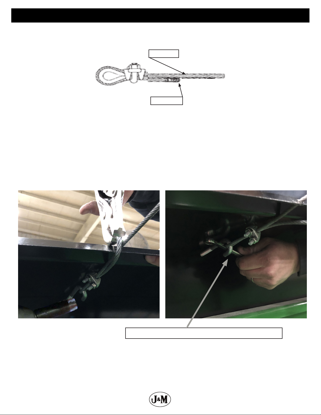
10 ........................................................................ Installing Cable Clamps
11 ....................................................................... Installing Spring Returns
12 .......................................................................Installing 1-1/4” Roll Tube
12 .....................................................................Installing 1”Tie Down Tube
13 ....................................................................... Installing Roll Tarp Stops
13 ....................................................Installing Pop Rivets on 1-1/4”Roll Tarp Tube
14 .....................................................................Installing the Crank Handle
15 ......................................................................................Tarp Rope
Electric Roll Tarp
17 ........................................................Removing Parts (if previously equipped)
17 ........................................................................Electric Roll Tarp Mount
18 ..................................................... Attaching Electric Roll Tarp Arm and Motor
18 ............................................................................Harness Installation
19 ...................................................................................Switchboard
20 ..............................................................................Wiring Schematic
21 ............................................................. Aligning the Tarp/Troubleshooting
Repair Parts List
22-23 ............................................................Repair Parts for Manual Roll Tarps
24 ................................................................Repair Parts List - Standard Carts
25 .........................................................Repair Parts List - Extended Reach Carts
26 ............................................................. Repair Parts List - Drag Series Carts
27-28 ............................................................Repair Parts for Electric Roll Tarps

3
Endcap Assembly
Assemble endcap at the ground level. Attach the endplate to the endcap using 1/4” x 1/2”serrated ange hex
bolts and 1/4” serrated ange hex nuts. Tighten the hardware once nished.
Rear Endplate
Rear Endcap
1/4” x 1/2” SF Hex Bolts
NOTE: Before beginning assembly, read the grain carts operator’s manual and comply with all safety rules and
operation procedures.
1/4” SF Hex Nut

4
Hanger Bracket
Model 525 to 875 Model 1000 to 1412
Model X2431 and GC-31T International
GC-24T International
NOTE: If you are installing the optional Electric Roll Tarp skip to Tightening Lip on pg. 5.
NOTE: All Leaner models have (2) hanger brackets. Center the hanger brackets with the rear runners and place the bracket as low as possible on the rear wall.
Model 1122 to 1522 Leaner
Rear Runner
Drag Cart Series
Place the hanger bracket with the four hole pattern, positioned at the top, in the center of the rear wall on the cart. Keep the hanger bracket as low as
possible on the rear wall. Mark the four holes then drill with a 7/16” bit. See gure bellow for specic model. For 1312, 1326, and 1522 models, the spring
return in the rear of the cart will obstruct where the hanger brackets are supposed to be installed. Instead use a bent hanger bracket (JM0048492 ) and
install directly under the sideboard at the top of the angled shell.

5
Hanger Bracket
Standard Grain Carts
Install the roll tarp hanger bracket. Use (4) 3/8”-16 x 1”Gr5 Z serrated ange hex bolts and (4) 3/8”-16 Gr5 Z serrated ange hex
nuts to attach the hanger bracket to the rear end panel brace. Tighten the hardware once installed.
Next install the hanger bracket hook and the rubber ap. Use a 1/2”-13 x 1-1/4” Gr5 Z hex bolt and a 1/2”-13 x 1-1/4”Gr5 Z centerlock
hex nut to attach the hook and ap to the hanger bracket. Tighten the hardware once installed.
Note: Make sure that hanger bracket hook is facing towards the cart when installed.
International Grain Carts
Install the roll tarp hanger bracket. Use (4) M10-1.5 x 25 Gr8.8 YZ serrated ange hex bolts and (4) M10-1.5 Gr8.8 YZ serrated ange
hex nuts to attach the hanger bracket to the rear end panel brace. Tighten the hardware once installed.
Next install the hanger bracket hook and the rubber ap. Use a M12-1.75 x 50 Gr8.8 YZ hex bolt and a M12-1.75 Gr8.8 YZ nylon lock-
ing hex nut to attach the hook and ap to the hanger bracket. Tighten the hardware once installed.
Note: Make sure that hanger bracket hook is facing towards the cart when installed.
Center the tightening lip from the front to the rear of the cart on the opposite auger side of the grain cart. Depending on the
length of your grain cart, there maybe a total of two tightening lips. If there is two, position the inside edge of each tightening lip
to the center of the grain cart. Make sure that the tightening lip is ush to the inside of the sideboard. The holes may already be
pre-drilled for installation or they may need to be drilled out with a 1/4” drill bit. Use a pair of C-clamp vise grips to temporarily
hold the tightening lip in place. Bolts will be installed in a later step.
Hanger Bracket
Flapper
Tightening Lip

6
Installing the Rear Endcap
Place the Rear Endcap Assembly onto the back of the grain cart. Slide the endcap to the right until it makes contact with the corner
bracket.
Using a 1/4” drill bit, drill through the hole closest to the corner bracket. Once drilled, fasten with a 1/4” x 1/2” serrated ange hex
bolt and nut. Now drill the opposite side and fasten with a 1/4”x 1/2” hex bolt and serrated ange nut.
Now drill the remaining holes for the rear endcap. All the holes that need drilled run horizontally with the hole that was just
drilled.
NOTE: While drilling, pull up on the front of the endcap
so the faceplate will lie parallel with the rear grain cart
wall.
Sideboard Corner
Note: While drilling, pull up on the front of the endcap so the faceplate will lie parallel with the rear grain cart
wall.
Place 1/4”x 1/2” hex bolts and serrated ange nuts in the remaining holes and tighten the hardware once nished.

7
Rear Endcap Support Brace
Install the endcap brace. The purpose of the endcap brace is to hold the inside of the endcap up approximately 1” higher than the
outside of the endcap. Drill a hole using a 1/4”drill bit rst followed by a 7/16” drill bit. The hole should be placed onto the nearest
crossbrace which is welded to the shell body. The hole should be located somewhere between the middle of the endcap and the
inside of the endcap. To accomodate for height adjustment, two braces will be used to support the endcap. Use the combination
that raises the inside lip of the endcap 1”above the outside edge of the endcap. Use 3/8” x 1” serrated ange hex bolts and nuts to
attach the braces to the grain cart.
1”
InsideOutside

8
Tightening Rear Endcap
Pull the tightening lip tight against the opposite auger side of the grain cart. Using a 1/4” bit, drill through the hole on the top of
the endcap. Fasten the endcap by using a 1/4” x 1-1/2” bolt and 1/4” serrated ange nut. Tighten the bolt. Now go to the other end
of the endcap and repeat the same procedure.
Now place (3) 3/8”J-bolts into the three holes closest to the auger side in the rear endcap. Fasten the J-bolts with (3)
3/8” locknuts. Use the plastic 3/8” ribbed push in rivet to plug the remaining hole. Leaner carts use four J-bolts and
wont require a ribbed push in rivet.
Rear of Cart
Opposite Auger Side
Auger Side
J-Bolts
Lock Nuts
Installing J-Bolts
NOTE: DO NOT tighten past ush.

9
Installing the Front Endcap
Install the front endcap assembly using the same procedure used to install the rear endcap assembly. Do not forget the endcap
brace. (See pages 6-8) On the front faceplate, use the plastic 3/8” ribbed push in rivets to ll the four 3/8” holes.
NOTE: If your tightening lip is centered and there are no holes visible through your lip lock and sideboard, holes
will need to be drilled wherever there are slots in the lip lock. Use a 1/4” drill bit to accomplish this. Now make sure that
all of the tarp bows are perpendicular to the auger side of the cart and drill 1/4” holes through the sideboards. This should
only be the case on later model grain carts.
Installing Tarp Bows
Install all of the tarp bows. Use (4) 1/4”x 3” hex bolts and (4) 1/4” serrated ange nuts for each bow.

10
Installing Cable Clamps
NOTE: Make sure that the base of the clip bears on the live end of the rope and the “U” of the
bolt bears on the dead end.
Now thread all three cables through the front endcap pulling the end without the cable clamps through rst.
NOTE: Make sure to pull from front to back.
Next guide the cables over the arched bows and thread them through the existing holes on the rear endcap. Now feed the
cables through the cable clamps.
NOTE: Make sure that the base of the clip bears on the live end of the rope and the “U” of the
bolt bears on the dead end.
Place the loop into the J-bolt. Use a vise grip to pull on the cable. Pull the cable tight. To remove all slack from the cable, aggres-
sively tap the cable while applying tension with the vise grips. Then tighten the cable clamp. Once the clamps are tightened,
tighten the J-bolts. Insert a wrench into the hook of the J-bolt and tighten the nut.
Live End
Dead End
Use wrench or bolt to hold the J-bolt while tightening.
Using a cable clamp, feed one end of the cable through the cable clamp, make a small loop, then tighten the cable. Do this with all three cables.

11
Installing the Spring Return
Place the spring return as close to the front endcap and butt the side of the spring return, with the cable loop, against the welds
on the corner of the grain cart.
NOTE: For single auger cart make sure that the spring return is level with the ground and that the spring return is
not hindered by any part of the cart. The exception to this rule is the 32 series cart. They have the spring return
lined up with top of the cart.
Use a 1/4” drill bit to make your rst hole. Then fasten the spring return to the cart using 1/4” x 3” self tapping screws. Next drill
through the remaining holes and insert the self tapping screws. Repeat process for back side of grain cart, installing the spring
return on the opposite auger side.
Cable Loop

12
Installing 1-1/4” Square Roll Tube
Prepare the canvas tarp. Spread the canvas tarp out so that the stiening patches are on the opposite auger side with the shiny
side down.
For grain carts with a capacity of 875 bushels and lower, slide the tarp guide roller onto the 1-1/4” square roll tube. Install the
1-1/4” square roll tube through the front end of the opposite auger side canvas tarp end.
For grain carts with a capacity of 1,000 bushels or greater, slide the 1-1/4” square roll tube through the rear end of the opposite
auger side canvas tarp end. Slide the tarp guide roller onto the front end of the 1-1/4” square roll tube. Slide the cable spool into
the front end of the 1-1/4”square roll tube. Line up the holes in the cable spool with the holes in the 1-1/4” square roll tube and
insert the roll pin.
Front of Cart
Feed the 1” square tie-down tube through the auger side tarp end. On the front of the grain cart, measure 3” from the end of the
tube. This is where the canvas tarp should stop. Now measure 3/4” on the canvas tarp. Drill a 1/4”hole through the tarp and the
rst wall on the tube. Next install a pop rivet using a hammer. Now go to the opposite end of the same tube and pull the tarp
tight. Measure 3/4”from the end of the tarp, drill a 1/4”hole and install another pop rivet.
3” 3/4”
1” Square Tie-
Down Tube
1-1/4” Square Roll
Tube
Opposite
Auger
Side
Auger Side
Installing 1”Tie Down Tube
1” Square Tie-
Down Tube
1-1/4” Square
Roll Tube
Canvas Tarp

13
Installing the Roll Tarp Stops
Push down on the 1-1/4”square roll tube on both ends and in the center to fully extend the canvas. Line the roll tube cable spool up
with the spring return cable. Drill a 1/4”hole through the rst stiening patch. Fasten the canvas tarp using a pop rivet. Go to the rear
of the cart, pull the canvas tarp tight, and repeat the process. Then install pop rivets at the remaining stiening patches. Once nished
slip the spring return cable loop over the cable spool.
Next place the 1” tube under the top bolt of the back corner bracket on the auger side. Drill a 1/4” hole through the tube and side-
wall approximately 18” to 24” in from the corner of the cart. Then re-drill the hole with a 7/16” bit. Place a 3/8”x 2” bolt through the
roll tarp stop, 1” square tie-down tube, and grain cart sidewall. Fasten with a 3/8” serrated ange nut. Now repeat this process at
the front of the cart. For the center hole slightly lift the 1” square tie-down tube approximately 1” higher than the two other holes.
Repeat the process to drill a 7/16”hole. Place a 3/8” x 2” bolt through the roll tarp stop, 1” square tie-down tube, and grain cart
sidewall and fasten with a 3/8”serrated ange nut .
NOTE: For grain carts that have a center splice make sure that the 1” tube is above the top bolt of the center splice.
18”-24”
Installing Pop Rivets on Roll Tube

14
Installing the Crank Handle
Slide tarp guide roller over rear end of 1-1/4” square roll tube. Then slide one washer over, then the spring return cable, then the next
washer. Now attach the knuckle to the roll pipe. Use (2) 3/8” x 2” hex bolts along with (2) 3/8”lock nuts. Attach the crank handle to the
universal joint. Install the crank handle using (1) 1/4”x 2-1/2” bolt and (1) 1/4” locknut. The universal joint may be pre-assembled to the
crank handle.
NOTE: If you are installing the optional Electric Roll Tarp go to top of the next page.
Check for proper function of the of the Roll Tarp.
Auger Side Opposite Auger Side

15
Tarp Rope
• Unroll the roll tarp completely and let it hang down to its lowest point on the opposite auger side.
• Line bracket up below where the roll tube ends and right behind the lip on the endcap, and use 1/4”x
1-1/2” self tapping screw to attach bracket to the cart. (See Pictures 1 & 2)
• Roll the tarp all the way up.
• Drape rope completely across the cart. Pull the rope to eliminate slack then let hang so that rope is
not too tight and aligned right behind endcap lip. (See Picture 3)
• Mark bracket where rope ends and fasten bracket to cart with 1/4” x 1-1/2” self tapping screws.
The process below is to be completed at the front and back ends of the cart.
Picture 1 Picture 2
Picture 3

16
Installing Electric Roll Tarp

17
Remove the Knuckle from the roll tube if previously installed.
Un-tighten both 3/8”locknuts, then pull the knuckle away
from the tarp. Keep knuckle and crank handle.
Un-install the hanger bracket if previously installed. Re-
move the (4) 3/8”x 1” serrated ange hex bolts and nuts
then remove the hanger bracket from the grain cart.
Install the bolts back into their original holes. Keep the
hanger bracket.
Place the electric roll tarp mount in the middle of rear slope as far up as it can go. Mark and drill (6) 7-16” holes. Attach the mount
to the grain cart using (6) 3/8”x 1” serrated ange hex nuts and bolts. Tighten hardware once installed.
Electric Roll Tarp Mount
Removing Parts (if previously installed)
The Spring return on the rear of the cart doesn’t need to be removed.

18
Attach Electric Roll Tarp Arm and Motor
Attach the electric roll tarp arm to the mount. Use (2) 1/2”x 1” hex bolts and (2) 1/2” hex nuts.
Adjust the roll tarp arm to the correct length, tighten the two set screws, and attach the motor to the roll tube. Once the motor is
attached drill a 3/8” hole through the spline using the hole in the motor shaft as a guide. Fasten the motor to the roll tube using a
5/16” x 2” hex bolt and a 5/16” locknut. Tighten hardware once nished.
Drill 3/8” hole
through spline
Harness Installation
Route the two wires coming from the electric tarp arm to the front leg. Drill holes accordingly.

19
Switchboard
Position the Electric Roll Tarp Switch Mount on the front auger side leg in a position that it will not interfere with any other
component of the grain cart and so that the power cables will reach from the battery to the Switchboard. Use the electric roll tarp
switch mount as a guided to mark the two holes. Once marked, drill (2) 9/32” holes.
Attach both of the relays to the electric roll tarp switch mount using a 1” x 1/4” hex bolt and 1/4” serrated ange hex nut. Attach
the 35 amp breaker with (2) 8-32 x 5/8”phillips pan head bolts. Using (2) 10-24 x 1” slotted hex head bolt and (2) 10-24 serrated
ange hex nuts attach the 20 amp breaker and snap the 12V to 12V battery charger into the bracket.
Now install the assembled mounting bracket using (2) 1/4”x 3-1/2” hex bolts, (2) 1/4” locking hex nuts and (2) 2”black spacers.
Black Spacers
Black Spacers
Relays
20 Amp Breaker
Battery Charger
1” x 1/4” hex bolt
35 Amp Breaker
Now make all of the connections using the provided wires and hardware according to the schematic on the next page.

20
Wiring
Main Wiring
Harness
M1
M1
M2
M2B-B+
S2 S1
CLOSEOPEN
RAISE LOWER
TOW
CHARGER
2024-07
35 A
BLACK
YELLOWYELLOW
BLACK
RED
RED
BLACK
BLACK
RED
RED
RED
BLACK
GREEN BLUE
BLACK
YELLOW
BLACK
20 A
Gold Terminal
35 A
OPEN CLOSE
LOWERRAISE
This manual suits for next models
10
Table of contents
Other J&M Farm Equipment manuals

J&M
J&M Trail-Blazer TB-6000 User manual

J&M
J&M 1522 User manual

J&M
J&M 375ST Speed Tender User manual

J&M
J&M GC31t-1 User manual

J&M
J&M NITRO-GRO 5010 User manual

J&M
J&M nitro gro 6018 User manual

J&M
J&M Speed Tender 535-ST User manual

J&M
J&M HT-974 User manual

J&M
J&M Torsion Flex User manual

J&M
J&M 32 Series User manual