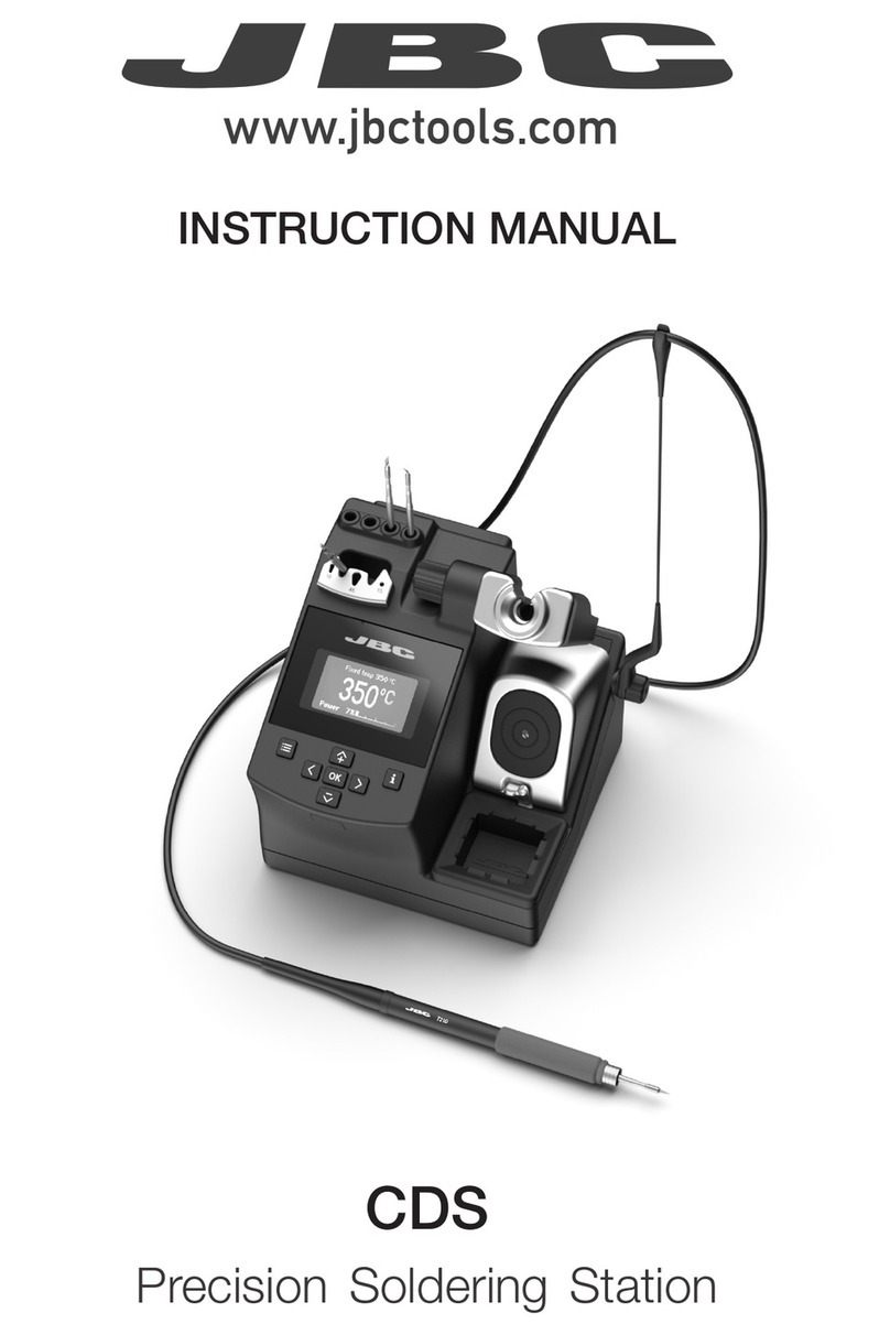
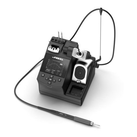
jbc AD 4200 User manual

USA Version
AD 4200
DUAL SOLDERING STATION

1
We appreciate the confidence you have placed in JBC in purchasing this station.
It is manufactured to the most stringent quality standards in order to give you the
best possible service. Before turning on your station, we recommend you to read
these instructions carefully.
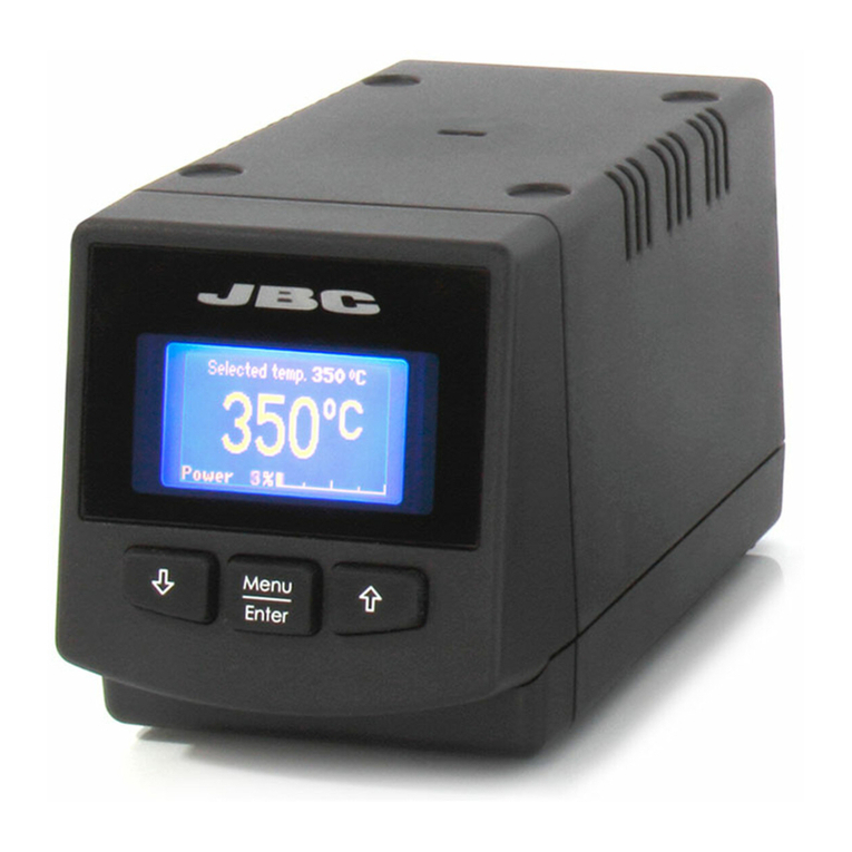
You have pursached a Advanced AD 4200 Control Unit.
In order to complete the soldering station you should choose the suitable handpiece or desoldering
tweezers, the stand and the cartridges for the task to do. The Control Unit is only for handpieces 2210,
2245 and the hot tweezers PA 1200 or PA 4200 and corresponding cartridges.
Control Unit
AD 4200 USA Ref. 4200100
*Hot tweezers stand
PA 8420
Ref. 0748420
*Hot tweezers
PA 4200
Ref. 4200000
*These elements are not
supplied with the control
unit
*Cartridges for the
hot tweezers PA 4200
Temperature
selector
Equipotential
terminal
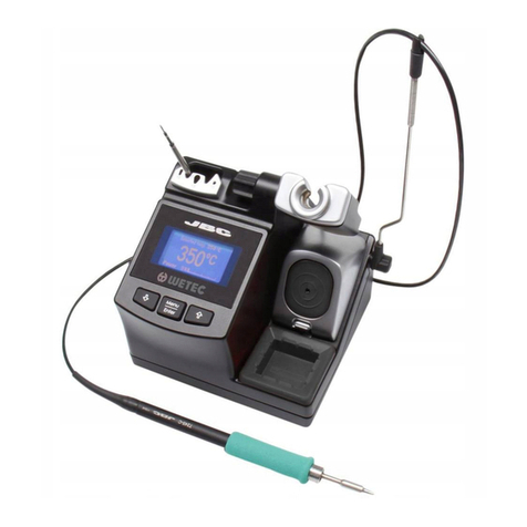
Dual soldering station
*Soldering iron stand
AD 8200
Ref. 0268200
*Handpiece 2210
Ref. 2210000
*Handpiece 2245
Ref. 2245000
*Cartridges 2210
*Cartridges 2245 *Micro hot tweezers
PA 1200
Ref. 1200000
*Cartridges 1200
*Hot tweezers stand
PA 8100
Ref. 0748100

2
Structure of Advanced soldering stations
system
The Advanced series has basic modules giving
you full flexibility for choosing what you need for
the work in hand, the modules being supplied
separately.
Dual control unit
-AD 4200 USA Ref.4200100
Model AD 4200 can be used with two tools
simultaneous, either handpieces or hot tweezers.
Can be used with either combination of 2210 and
2245 handpieces and the hot tweezers PA 1200 and
PA 4200.
Handpieces
-2210 Ref.2210000
Power: 20W. For high precision work, SMD, etc.
-2245 Ref.2245000
Power: 50W. For general soldering work.
Hottweezers
-PA 1200 Ref.1200000
For general precision desoldering with SMD
components.
Power:40W.
Effective power per cartridge fitted: 20W.
-PA 4200 Ref.4200000
For general desoldering and soldering work in
professional electronics.
Power:100W.
Effective power per cartridge fitted: 50W.
Cartridges
-Rangeofcartridges2210 (forthe2210 handpiece).
-Rangeofcartridges2245 (forthe2245 handpiece).
-Range of cartridges for micro hot tweezers PA
1200.
-Range of cartridges for hot tweezers PA 4200.
Stands
-Soldering iron stand AD 8200 Ref.0268200
-PA 8420 Ref.0748420
Stand for the hot tweezers PA 4200.
-PA 8100 Ref.0748100
Stand for the hot tweezers PA 1200 and PA 4200.
For a dual soldering station work properly is
necessary: the dual control unit, a handpiece or the
hot tweezers, and the corresponding stand and
cartridge.
Dual control unit AD 4200
The station is supplied with:
-Control unit.
-Connection cable to mains.
-Instructions manual.
-Transport packaging.
Technical specifications
-Temperature selection from 200 to 700°F (±5%).
-Power: 135W.
-Safety transformer, mains separator and double
isolation, with integrated fuse of temperature
protection.
-Input: 120V 60Hz. Output: 24V.
-Electrical protection Class I.
-Total weight of unit: 12.5 lbs.
-ESD protected housing.
Typical surface resistance: 105-1011Ohms/
square.
-Equipotential connector is earth connected to the
plug feed of the station.
listed.
RECOMMENDATIONS FOR USE
For soldering and desoldering
-Clean the contacts and the printed circuit to
be desoldered of dust or dirt.
-Preferably select a temperature below 662°F.
Excess temperature may cause the printed
circuit tracks to break loose.
-The tip must be well tinned for good heat
conduction. If it has been inoperative for any
length of time, it should be retinned.

3
HANDPIECES 2210 AND 2245
The following soldering handpieces can be
connected to the AD 4200 station:
-Handpiece 2210 ref. 2210000. Power:20W. For
high precision work, SMD etc. Available
cartridges 2210: see page 15.
-Handpiece 2245 ref. 2245000. Power:50W.For
general soldering work. Available cartridges
2245: see page 14.
The handpieces and cartridges 2210 and 2245
comply with the MIL-SPEC-2000 referring to the
potential difference between the soldering tip and
ground connection, must be less than 2 mV.
For a soldering handpiece to work properly, the
following components are required: the control
unit, soldering iron stand, one handpiece and one
cartridge.
Thesolderingironisconnectedtothestationinthe
following way:
The cable connection of the soldering iron is
connected to the plug in the soldering iron stand
AD8200andthecableconnectionofthe soldering
iron stand is plugged into the terminal of the
station.Pleasefindtheconnectionplanonpage1.
OPERATION
LED lights
Red LED -ON- when lit, it indicates that the station is
plugged in the mains.
Green LED -READY- when lit, it indicates that the
system is ready and correctly set for working.
The green led light is on after a few seconds, is the
time needed to carry on the self-checking system.
The green light is pulsing when the soldering iron is
in sleep mode.
If the green led is not lit, the reason why, will be one
of the following:
1. The handpiece or the cartridge are not plugged
in.
2. The maximum available power has been
exceeded for too long - e.g. in a very thick
soldering at the high repetition rates.
3. The handpiece or cartridge has a short
circuit or an open circuit.
4. Any other trouble preventing the system from
working properly.
The green led goes off when the cartridge tip
touches the extractor and the station stops the
power supply.
The handpiece will reset itself automatically should
the cartridge short circuit or go open circuit.
Should the handpiece be subject to:
-An electrical surge or the cartridge has not been
fitted correctly.
Please turn the unit off and switch on again to
reset.
Handpiece 2245 Ref. 2245000
Handpiece 2210 Ref. 2210000
Cartridges

4
Sleep function
One of the Series Advanced features is that when
the handpiece is placed in the holder, the
temperature at the tip drops automatically to the
sleep temperature. This function is only possible
because of the quick response time which does
not make the user realise the temperature rise to
reach the selected temperature. Also by this, the
oxidation of the tinning of the tip is considerably
reduced and tip life is extended.
To indicate that the soldering iron is in sleep-mode,
the green led starts pulsing. These parameters can
bemodifiedusingtheConsoleAC2600 Ref.2600000.
In order to take advantage of the above
mentioned feature and as a security measure,
it is necessary to place the handpiece on stand
when the iron is not being used.
2- Place the handpiece on top of the new cartridge,
press it slightly down and remove the handpiece.
Changing the handpiece's cartridge
With the Advanced system, the cartridge can be
changed quickly, without turning off the station,
so you have two soldering irons in one. Here is
what to do to change the cartridge:
1- Place the handpiece and remove the cartridge.
Fume extractor accessories
Specially designed for the Advanced Series
handpieces 2210 and 2245. Easily clips onto the
handpiece and can be quickly removed for easy
maintenance.
For handpiece 2245
0495000
For handpiece 2210
0265000 3- Press the cartridge into the opening A, B or C:
A. For straight cartridges 2210.
B. For curved cartridges 2210.
C. For cartridges 2245.
When connecting an old version solder stand, it may
happen that the sleep function does not work.
To resolve this problem, you should make a bridge
between pins number 3 and 5 from the aerial
connector of the cable of the stand, that plugs in
the station.
Aerial connector
Bridge between
pin number 3 & 5

5
Alignment
XX
XXXXX
Important.
-It is essential to insert the cartridge till the end
for a good connection. Take the mark a s
reference.
AC 2600
Ref.2600000
Console AC 2600
The console AC 2600 is designed for modifying the
originalregulation programparametersof thefollowing
Advanced control units:
-AD 2000 soldering station.
-AD 2200 soldering station.
-AD 4200 dual soldering station.
-AR 5500 desoldering station.
-AM 6000 rework station.
Changes avalaible to perform:
-Fixing the the working temperature.
-Selection of temperature units in Celsius grades
-°C- or Fahrenheit -°F-.
-Modification of sleep temperatures and standby
times.
-Adjustment of temperature.
-Setthe parameters back to theoriginalparameters.
-Read-out data:
Working hours.
Sleep cycles and sleep hours.
Cartridge and iron changes.
Program version.
Advanced series cartridge
Cartridge is made of the heating element which has the
heating system, temperature sensor and long life tip.
Long-life tip is basically made of:
1Copper
2Iron
3Nikel
4Chromium
5Tin plate
Long-life tip care
Except the copper core, the rest of metals are placed
galvanically on layers relatively thin, so it is necessary
to avoid the reasons which can cause its destruction.
To clean the tips, use the sponge included with
the stand and check it is lightely moisted.
To re-tin the soldering tips, we recommend using
the tip tinner/cleaner TT 9400 ref. 9400000.

6
HOT TWEEZERS
AD 4200 station allows to connect two different
models of tweezers, each one with its respective
range of cartridges and stand:
-Micro hot tweezers PA 1200 ref. 1200000.
-Hot tweezers PA 4200 ref. 4200000.
For tweezers to work properly, the following
components are required: control unit, hot tweezers,
a stand and a set of cartridges corresponding to
the chosen tweezer.
Hot tweezers
PA 4200
Ref. 4200000
Cartridges for the hot
tweezers PA 4200
Stand PA 8420
Ref. 0748420
The tweezers are connected to the station in the
following way:
The cable connector of the tweezers is plugged
intotheconnectorofthestand.Thecableconnector
of the stand is connected to the terminal of the
station. Please find the connection plan on figure.
Cartridges 1200
Micro hot tweezers
PA 1200
Ref. 1200000
Stand PA 8100
Ref. 0748100
(This stand is either for tweezers
PA 1200 and PA 4200)

7
OPERATION
LED lights
Red LED -ON- when lit, it indicates that the station is
plugged in the mains.
Green LED -READY- when lit, it indicates that the
system is ready and correctly set for working.
The green led light is on after a few seconds, is the
time needed to carry on the self-checking system.
The green light is pulsing when the hot tweezers are
in sleep mode.
If the green led is not lit, the reason why, will be one
of the following:
1. The hot tweezers or the cartridge are not
plugged in.
2. The maximum available power has been
exceeded for too long - e.g. in a very thick
soldering at the high repetition rates.
3. The hot tweezers or cartridge has a short circuit
or an open circuit.
4. Any other trouble preventing the system from
working properly.
The hot tweezers will reset itself automatically should
the cartridge short circuit or go open circuit.
Should the hot tweezers be subject to:
-An electrical surge or the cartridge has not been
fitted correctly.
Please turn the unit off and switch on again to reset.
Sleep function
One of the Series Advanced features is that when
the hot tweezers are placed in the holder, the
temperature at the tip drops automatically to the
sleep temperature. This function is only possible
because of the quick response time which does
not make the user realise the temperature rise
to reach the selected temperature. Also by
this, the oxidation of the tinning of the tip is
considerably reduced and tip life is extended.
To indicate that the hot tweezers are in sleep-
mode, the green led starts pulsing. These
parameters can be modified using the Console
AC 2600 Ref. 2600000.
In order to take advantage of the above
mentioned feature and as a security measure,
it is necessary to place the hot tweezers on
stand when the iron is not being used.

8
MICRO HOT TWEEZERS PA 1200
For micro hot tweezers to work properly, the
following modules are required:
-Control unit.
-Micro hot tweezers PA 1200 ref. 1200000. For
general precision desoldering with SMD
components.
Power:40W.
Effective power per cartridge fitted: 20W.
-Stand PA 8100 ref. 0748100.
-Aset of cartridges (see range).
Changing the cartridge
To extract the cartridge the screw needs to be
unfastened and the cartridge pulled out. Insert
the new cartridge and push it thoroughly. Then
check that both tips of the tweezers coincide
and screw it.
Important.
-It is essential to insert the cartridge till
the end for a good connection. Take the
mark as reference and check that both
parts of the tweezer coincide.
Alignment
RANGEOF CARTRIDGES
PA 1200 has an individual temperature control
for each cartridge so it is supplied individually.
1200
JBC
1200-001
95238
CHIP COMPONENTS
IC COMPONENTS
1200-001
ø0.007”
1200-002
ø0.007” 0.059”
1200-004
ø0.027” 0.059”
1200-005
0.196”
1200-003
0.118”
PATENT PENDING
All the cartridges shown are actual size.

9
A
A
A
ØA
A
Ref. A inches
2245-271 0.059"
2245-272 0.078"
Chip components
Ref. A inches
2245-273 0.157"
2245-274 0.236"
2245-275 0.314"
2245-276 0.393"
2245-277 0.590"
2245-278 0.787"
Dual in line IC
Ref. A inches
2245-279 0.314"
2245-280 0.433"
QFP and PLCC
Ref. A inches
2245-281
2245-282
Cable stripper
RANGEOF CARTRIDGES
PA 4200 has an individual temperature control
for each cartridge so it is supplied
individually.
2245-281 2245-282
0.137"
max.
JBC reserves the right to make technical changes without
prior notification.
HOT TWEEZERS PA 4200
For hot tweezers to work properly, the following
components are required:
-Control unit.
-Hot tweezers PA 4200 ref. 4200000. For general
desoldering and soldering work in professional
electronics.
Power:100W.
Effective power per cartridge fitted: 50W.
-Stand PA 8420 ref. 0748420 or stand PA 8100
ref. 0748100.
-Aset of cartridges (see range).
Changing the cartridge
To extract the cartridge the screw needs to be
unfastened and the cartridge pulled out. Insert
the new cartridge and push it thoroughly. Then
check that both tips of the tweezers coincide
and screw it.
Important.
-It is essential to insert the cartridge till the end
for a good connection. Take the mark as
reference and check that both parts of the
tweezer coincide.
PATENT PENDING

11
JT7000
Hot-air flow repair station for desoldering all types of
SMD’s particulary QFPs and PLCCs of any size.
TE 5000
Hot-air flow repair station designed for soldering
and desoldering small and medium-sized SMDs.
AR5500
Desoldering station which enable the rapid
desoldering of all kinds of insertion components.
AM6000
Station for rework and repair of through-hole and
SMT boards.

12
ELECTRIC WIRING DIAGRAM

13

14
RANGE OF CARTRIDGES
TO SOLDER SMT IC
All the cartridges shown are actual size.
2245-003
Ø
0.023”
2245-004
Ø
0.039”
2245-005
Ø
0.051”
2245-012
0.177”
x
0,07”
0.177”
x
0,07”
2245-009
QFP
2245-010
PLCC
2245
*The total lenght of these cartridges is 20mm longer
in order to reach areas of difficult access
2245-001
2245-201*
Ø
0.015”
Ø
0.007”
Ø
0.039”
2245-029
2245-032
2245-030
2245-036
Ø
0.015”
2245-034
2245-033
2245-035
2245-037
Ø
0.007”
Ref. 2245-007
07
2245-0
JBC
66752
Ø
0,015”
Ø
0.078”
Ø
0.023”
PATENT PENDING
0.007”
BEVEL EDGETIP
2245-039
0.236”
FINE PITCH
ØA
2245-006
2245-206*
0.181”
x
0.047”
0.039”
x
0.019”
0.078”
x
0.031”
2245-007
2245-008
0.118”
x
0.039”
2245-011
2245-211*
Ref. ØA
2245-031
2245-038
0.098”
0.137”
Ø
0.110”
Ø
0.015”

15
2210-009
2210-001
2210-003
2210-005
2210-002
2210-004
2210-006
2210-008
2210-007
Ø
0.011”
Ø
0.007”
Ø
0.023”
Ø
0.027”
0.09”x0.027”
Ø
0.007”
Ø
0.039”
Ø
0.039”
0.051”x0.023”
Ø
0.007”
2210-010
2210
Ref. 2210-001
JBC
2210-001
95238
2210-012
Ø
0.027”
FOR CHIP
COMPONENTS
TUNNELTYPE
FOR DUAL IN LINE IC
FOR IC’S: QFP AND PLCC
A
AB
A
BLADETYPE
A
AB
A
Ref. A
2245-014
2245-013
0.393”
0.826”
Ref. A
2245-016
2245-017
2245-018
2245-019
0.074”
0.086”
0.133”
0.177”
Ref. A B
2245-020
2245-021
2245-022
2245-015
2245-026
0.232”
0.232”
0.295”
0.377”
0.574”
0.236”
0.393”
0.472”
0.708”
1.118”
Ref.
2245-023
2245-024
2245-028
2245-027
0.334”x0.334”
0.472”x0.472”
0.488”x0.590”
0.688”x0.688”
A x B

0780189-0
WARRANTY ENGLISH
The JBC 2 years warranty, guarantees
thisequipmentagainstallmanufacturing
defects, covering the replacement of
defectivepartsandallnecessarylabour.
Malfunctions caused by misuse are not
covered.
In order for the warranty to be valid,
equipment must be returned, postage
paid,tothedealerwhereitwaspurchased
enclosing this, fully filled in, sheet.
DATE OF PURCHASE
STAMP OF DEALER
SERIAL Nº
✂
MANUFACTURED BY
JBC Industrias, S.A.
Ramón y Cajal, 3 - 08750 MOLINS DE REI - SPAIN
Tel.: +34 93 325 32 00 - Fax: +34 93 680 49 70
http://www.jbctools.com e-mail:[email protected]
Other manuals for AD 4200
1
Table of contents
Other jbc Soldering Gun manuals