jbc B-IRON 500 User manual

INSTRUCTION MANUAL
Battery-Powered Soldering Station
B·IRON 500

2
Packing List
The following items are included:
This manual corresponds to the following references:
BIS-5A*
*according to purchased station model, suitable for:
120V - N. America / Taiwan
230V - India / Europe / United Kingdom
B·IRON Handel Charging-Base ........... 1 unit
Ref. 0032434
B·IRON 500 TOOL
Precision Handle .................................... 1 unit
Ref. B500-A
Includes Ref. 0031596 Cap for B·IRON handles.
Portable Display 7” for B·IRON ............. 1 unit
Ref. PDS-B
C210 Cartridge ............................................. 1 unit
Ref. C210001 (tip ø 0.3 mm)
Cap

3
40 mm
50 mm
60 mm
80 mm
100 mm
130 mm 130 mm
para manuales - color gris
200 mm
300 mm
* Included according to purchased station model.
Power Cord * ................................................ 1 unit
Ref. 0027380 120V - N. America / Taiwan
0027381 230V - India
0027382 230V - Europe
0027378 230V - United Kingdom
Manual ............................................................ 1 unit
Ref. 0033066
USB Cable (USB A to Micro USB) ................. 1 unit
Ref. 0028092
Brass Wool for
B·IRON Charging-Base ............................ 1 unit
Ref. CL0300
Already assembled in the charging-base
B·IRON Display Holder 5” to 7” ............. 1 unit
Ref. 0030723
Includes fixing knob

4
Features & Connections
Cartridge Exchanger
Cartridge Holder
Please read this manual and its safety guidelines thoroughly before using the product.
Ref. 0032465
Right-Side
Handle Charger
CL0301
Wiper for B·IRON
Charging-Base
CL0300
Brass Wool
for B·IRON
Charging-Base
(inside)
PDS
Portable Display 7”
for B·IRON
Ref. 0032434
B·IRON Handle Charging-Base

5
40 mm
50 mm
60 mm
80 mm
100 mm
130 mm 130 mm
para manuales - color gris
200 mm
300 mm
B·IRON 500 TOOL
Precision Handle
C210
Cartridge
Range
Features and Connections
Power Socket
USB Connector
Ref. 0028092
USB Cable
Safety Cap
Holder
Bluetooth
Connection
PDS
Portable Display 7”
for B·IRON
Display Support
Ref. 0030723
B·IRON Display Holder
5” to 7”
Ref. 0031596
Safety Cap for B·IRON Handle

5
4
1
23
Insert the fixing knob (3) and tighten it just enough
so that it stays in its place but the display holder
can be moved.
Quick Start
Connect the charging base to the mains (4).
If needed, the display can be connected to the
USB port (5) with the provided USB cable to keep
it charging while working.
4. Base Connection / Display Connection3. Display Placing
Insert the thin end of the display holder into the
upper area of the rear rail of the charging base
(1). Then carefully rotate the display holder 90
degrees (2) until it stands vertical.
1. Display Holder Assembling
Place the display on the support with its buttons
facing upwards and adjust the height of the
display holder.
Once the display holder is at the right height,
tighten the fixing knob completely to fix the
display in place.
Buttons
Tablet
Holder
Support Connector
for Display
2. Display Holder Setting
6

5. Turning on the Portable Display
Turn on the display by holding
down the power button and then
open the B·IRON app*:
* Note: The app can also be downloaded to your
own devices. To know how, see section “Installing
and Updating the B·IRON App”.
Power Button
3
1
4
2
6. Cartridge Insertion and Charging
Place the tool over a cartridge
and press the tool down to insert
the cartridge (1). To release the
tool with the cartridge from the
extractor, lift the tool upward (2).
Make sure that the cartridge is
appropriately inserted* into the
tool by gently pressing the tip
against the holes on the sides
of the cartridge exchanger (3).
*Important: Cartridges must
be inserted up to the mark for
a proper connection.
Place the tool on the tool charger
(4) to charge it. A beep will sound
to confirm that the tool is properly
placed and charging.
The sound can be turned up,
down or off using the buttons on
the display.
Note: Charge the tool
completely before using it for
the first time. It will take aprox.:
-30min for B·IRON 100 TOOL
-60min for B·IRON 500 TOOL
-30min for B·NANO TOOL
-40 min for B·TWEEZERS TOOL
For more information on how to change cartridges and the use of the cartridge exchanger, see section
“Cartridge Exchanger and Cartridge Holder”.
Inserting Fixing Charging
Mark
7
40 mm
50 mm
60 mm
80 mm
100 mm
130 mm 130 mm
para manuales - color gris
200 mm
300 mm

Tool
ON
MENU
28174
24 W
100%
18 W
100%
12 W
100%
6 W
100%
0 W
100%
10 seconds/div
V1.2
CHARGE
450 ºC
350 ºC
250 ºC
150 ºC
50 ºC
JBC
210
348ºC
5,7 W
80%
350ºC
Tool
ON
MENU
24 W
100%
18 W
100%
12 W
100%
6 W
100%
0 W
100%
10 seconds/div
V1.2
WORK
450 ºC
350 ºC
250 ºC
150 ºC
50 ºC
80%
JBC
210
350ºC
Tool
ON
MENU
24 W
100%
18 W
100%
12 W
100%
6 W
100%
0 W
100%
10 seconds/div
V1.2
CHARGE
450 ºC
350 ºC
250 ºC
150 ºC
50 ºC
JBC
210
348ºC
5,7 W
80%
350ºC
JBC#1
JBC#1
MENU
Tool1
2822
Tool ID
Hibernation delay
Temperature units
00:30
Maximum Temperature
400ºC
Sleep mode
Sleep temperature
150ºC
Working
Low battery
Power OFF
Charging
No cartridge
Tool Status
ºC
ºF
JBC
210
Lock Parameters
Locked
Unlocked
Return to Work
Tool1
Tool ID
28714
Hardware
Software
0028283
X886787
Update File
File
Hardware
Software
Select your Firmware
-
-
Update
MENU
JBC
210
Return to Work
JBC#1
2822
Work
Settings
Counters
Update
Documents
Light Theme
Dark Theme
Disconnect
JBC#1
Update
Tool
ON
MENU
JBC#1
24 W
100%
18 W
100%
12 W
100%
6 W
100%
0 W
100%
10 seconds/div
V1.2
WORK
450 ºC
350 ºC
250 ºC
150 ºC
50 ºC
80%
JBC
210
350ºC
Tool1
Tool1
Tool1
Tool1 Tool2
Tool3
Tool
ON
MENU
24 W
18 W
12 W
6 W
0 W
10 seconds/div
V1.2
CHARGE
450 ºC
350 ºC
250 ºC
150 ºC
50 ºC
JBC
210
80%
350ºC
JBC#1
348ºC
6 W
10
10
1
6
7
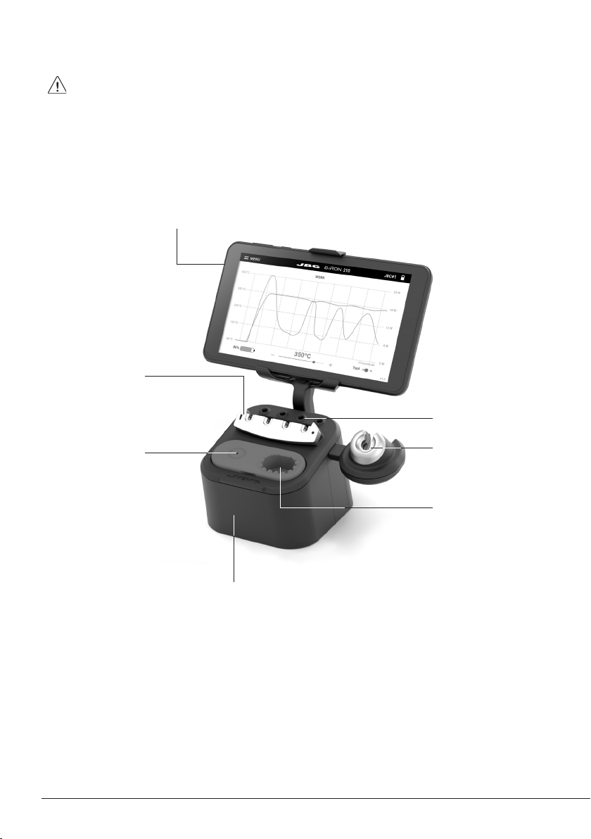
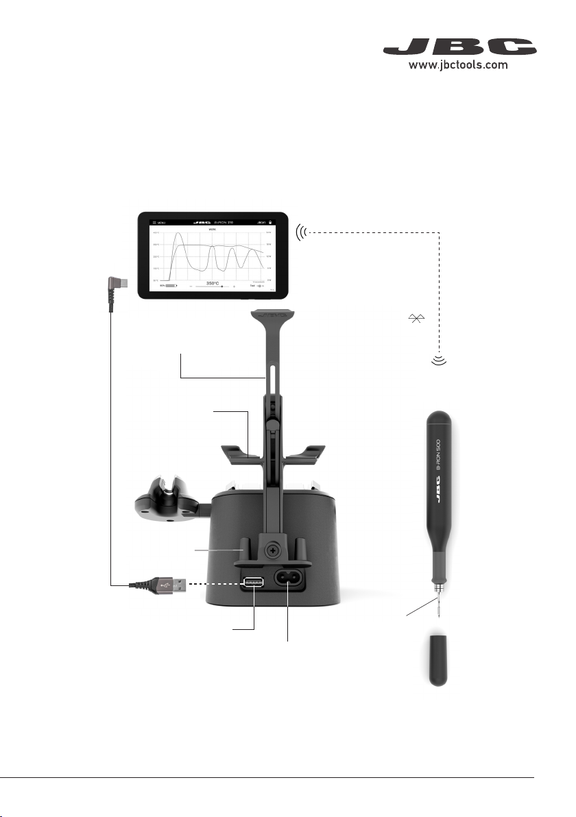
Status Lightband see table at the right
Safety Cap
Safety Cap and Cap Holder
Cap Holders
Status Lightband Detail
7. Tool Selection
Screw
Color Battery Status
green more than 50% charged
orange between 20% and 50% charged
red less than 20% charged
green
blinking
charging
(more than 50% charged)
orange
blinking
charging
(between 20% and 50% charged)
red
blinking
charging
(less than 20% charged)
no
color
safety cap on the handle
and/or power off
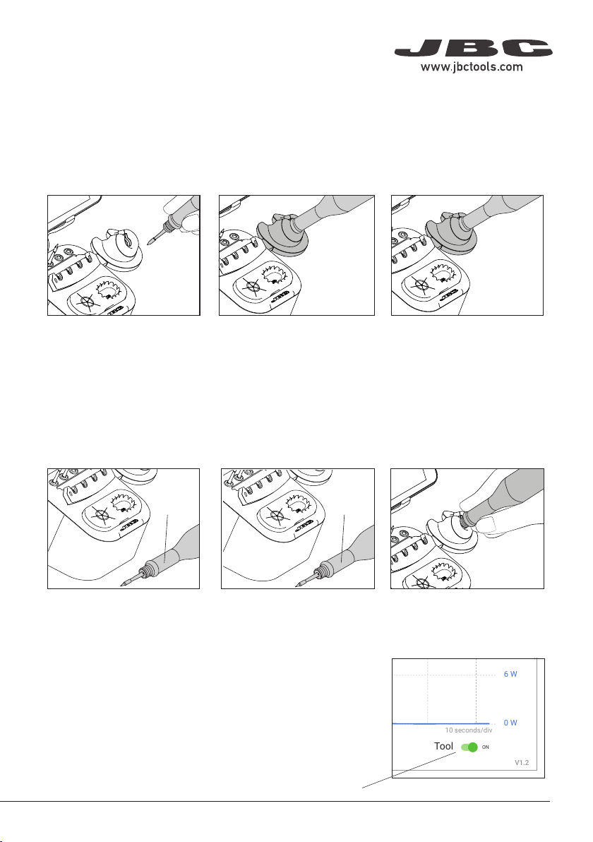
Thanks to the safety cap for B·IRON handles,
they can be safely transported even with a
cartridge inserted.
When the cap is placed onto the handle, the
cartridge stops heating immediately, data
transfer is cut off and the handle is disconnected
from the station. It turns off completely after 10
minutes of inactivity. This allows a greater saving
of the handles battery.
The charging base has a holder for two safety
caps on the back. This component can be
detached by loosening and removing the screw
in middle of the two holders (1).
While the tool is being used, the cap can be
stored on the cap holder.
Select the tool from the device list. If the tool is
not displayed on screen, make sure that the cap
is off and the tool has some battery. Try scanning
again by tapping Scan (6) on the display.
To add a second tool to the station once the first
one is connected, go to the main menu (7) and
tap Add device. Select your second tool from
the device list.
Tool Slection
Tool
ON
MENU
28174
24 W
100%
18 W
100%
12 W
100%
6 W
100%
0 W
100%
10 seconds/div
V1.2
CHARGE
450 ºC
350 ºC
250 ºC
150 ºC
50 ºC
JBC
210
348ºC
5,7 W
80%
350ºC
Tool
ON
MENU
24 W
100%
18 W
100%
12 W
100%
6 W
100%
0 W
100%
10 seconds/div
V1.2
WORK
450 ºC
350 ºC
250 ºC
150 ºC
50 ºC
80%
JBC
210
350ºC
Tool
ON
MENU
24 W
100%
18 W
100%
12 W
100%
6 W
100%
0 W
100%
10 seconds/div
V1.2
CHARGE
450 ºC
350 ºC
250 ºC
150 ºC
50 ºC
JBC
210
348ºC
5,7 W
80%
350ºC
JBC#1
Tool
ON
MENU
24 W
100%
18 W
100%
12 W
100%
6 W
100%
0 W
100%
10 seconds/div
V1.2
CHARGE
450 ºC
350 ºC
250 ºC
150 ºC
50 ºC
JBC
210
80%
350ºC
JBC#1
Tool1
Tool ID
28714
Hardware
Software
0028283
X886787
Update File
File
Hardware
Software
Select your Firmware
-
-
Update
MENU
JBC
210
Return to Work
JBC#1
Bi115
Bi210
User’s Manual
User’s Manual
Documents
MENU
JBC#1
JBC
210
Return to Work
2822
Work
Settings
Counters
Update
Documents
Light Theme
Dark Theme
Disconnect
Tool
ON
MENU
28174
24 W
100%
18 W
100%
12 W
100%
6 W
100%
0 W
100%
10 seconds/div
V1.2
CHARGE
450 ºC
350 ºC
250 ºC
150 ºC
50 ºC
JBC
210
348ºC
5,7 W
80%
350ºC
Work
Settings
Counters
Update
Documents
Light Theme
Dark Theme
Disconnect
JBC#1
348ºC
6 W
Tool1 Tool2 Tool3
Work
JBC#1
MENU
Tool1
2822
Tool ID
Hibernation delay (seconds)
00:30
Sleep mode
Sleep temperature
150ºC
Minimum Temperature
100ºC
Maximum Temperature
400ºC
Working
Low battery
Power OFF
Charging
No cartridge
Tool Status
Temperature units
ºC
ºF
JBC
210
Lock Parameters
Locked
Unlocked
Work
JBC#1
MENU
A1
2822
Tool ID
Hibernation delay (seconds)
10
Sleep mode
Sleep temperature
150ºC
Minimum Temperature
100ºC
Maximum Temperature
400ºC
Working
Low battery
Power OFF
Charging
No cartridge
Tool Status
Temperature units
ºC
ºF
JBC
210
Lock Parameters
Locked
Unlocked
Work
JBC#1
MENU
Tool1
2822
Tool ID
Hibernation delay (seconds)
00:30
Sleep mode
Sleep temperature
150ºC
Minimum Temperature
100ºC
Maximum Temperature
400ºC
Working
Low battery
Power OFF
Charging
No cartridge
Tool Status
Temperature units
ºC ºF
JBC
210
Lock Parameters
Locked Unlocked
Work
Enter PIN
OK
MENU
450 ºC
350 ºC
250 ºC
150 ºC
50 ºC
80%
Work
Settings
Counters
Update
Documents
Light Theme
Dark Theme
Add device
Disconnect
MENU
450 ºC
350 ºC
250 ºC
150 ºC
50 ºC
JBC
80%
350ºC
Devices
Documents
Light Theme
Dark Theme
Tool
ON
MENU
28174
24 W
100%
18 W
100%
12 W
100%
6 W
100%
0 W
100%
10 seconds/div
V1.2
CHARGE
450 ºC
350 ºC
250 ºC
150 ºC
50 ºC
JBC
210
348ºC
5,7 W
80%
350ºC
Tool
ON
MENU
24 W
100%
18 W
100%
12 W
100%
6 W
100%
0 W
100%
10 seconds/div
V1.2
WORK
450 ºC
350 ºC
250 ºC
150 ºC
50 ºC
80%
JBC
210
350ºC
Tool
ON
MENU
24 W
100%
18 W
100%
12 W
100%
6 W
100%
0 W
100%
10 seconds/div
V1.2
CHARGE
450 ºC
350 ºC
250 ºC
150 ºC
50 ºC
JBC
210
348ºC
5,7 W
80%
350ºC
JBC#1
JBC#1
MENU
Tool1
2822
Tool ID
Hibernation delay
Temperature units
00:30
Maximum Temperature
400ºC
Sleep mode
Sleep temperature
150ºC
Working
Low battery
Power OFF
Charging
No cartridge
Tool Status
ºC
ºF
JBC
210
Lock Parameters
Locked
Unlocked
Return to Work
Tool1
Tool ID
28714
Hardware
Software
0028283
X886787
Update File
File
Hardware
Software
Select your Firmware
-
-
Update
MENU
JBC
210
Return to Work
JBC#1
2822
Work
Settings
Counters
Update
Documents
Light Theme
Dark Theme
Disconnect
JBC#1
Update
Tool
ON
MENU
JBC#1
24 W
100%
18 W
100%
12 W
100%
6 W
100%
0 W
100%
10 seconds/div
V1.2
WORK
450 ºC
350 ºC
250 ºC
150 ºC
50 ºC
80%
JBC
210
350ºC
Tool1
Tool1
Tool1 Tool1 Tool2 Tool3
Tool
ON
MENU
24 W
18 W
12 W
6 W
0 W
10 seconds/div
V1.2
CHARGE
450 ºC
350 ºC
250 ºC
150 ºC
50 ºC
JBC
210
80%
350ºC
JBC#1
348ºC
6 W
10
10
Operation
The JBC Most Efficient Soldering System
This revolutionary technology can recover tip temperature extremely quickly. This allows the user to
work at a lower temperature.
Inactive
5 mins.
Tool Power Switch
Work Charge Mode
When the tool is lifted from
the tool holder, the tip of the
assembled cartridge will heat
up to the selected working
temperature.
While the tool remains on the
tool holder, it charges and the
tip will gradually cool down to
room temperature.
Hibernation Mode
When the tool is away from
the tool holder and remains
inactive (no movement for at
least 10 seconds), the tool goes
into Hibernation Mode and the
tip temperature gradually cools
down to room temperature.
After automatically turning
off, put the tool back on the
tool holder to turn it on again.
If the tool has been inactive for
a longer period of time (at least
5 minutes), it automatically
turns off.
Automatic Turn Off Turning the Tool Back On
Sleep Mode
If Sleep Mode is activated
(see section “Settings”), upon
placing the tool on its holder,
besides charging it enters Sleep
Mode. The tip temperature will
drop down and remain at Sleep
temperature.
Note: The tool can also be switched off/on manually. Tap the
Tool power switch on the display (bottom right) to switch it off/
on (if the tool is turned off, it will remain connected up to 5
minutes to the station but will not heat up the cartridge).
Inactive
10 secs.
8

Tool
ON
MENU
28174
24 W
100%
18 W
100%
12 W
100%
6 W
100%
0 W
100%
10 seconds/div
V1.2
CHARGE
450 ºC
350 ºC
250 ºC
150 ºC
50 ºC
JBC
210
348ºC
5,7 W
80%
350ºC
Tool
ON
MENU
24 W
100%
18 W
100%
12 W
100%
6 W
100%
0 W
100%
10 seconds/div
V1.2
WORK
450 ºC
350 ºC
250 ºC
150 ºC
50 ºC
80%
JBC
210
350ºC
Tool
ON
MENU
24 W
100%
18 W
100%
12 W
100%
6 W
100%
0 W
100%
10 seconds/div
V1.2
CHARGE
450 ºC
350 ºC
250 ºC
150 ºC
50 ºC
JBC
210
348ºC
5,7 W
80%
350ºC
JBC#1
Tool
ON
MENU
24 W
100%
18 W
100%
12 W
100%
6 W
100%
0 W
100%
10 seconds/div
V1.2
CHARGE
450 ºC
350 ºC
250 ºC
150 ºC
50 ºC
JBC
210
80%
350ºC
JBC#1
Tool1
Tool ID
28714
Hardware
Software
0028283
X886787
Update File
File
Hardware
Software
Select your Firmware
-
-
Update
MENU
JBC
210
Return to Work
JBC#1
Bi115
Bi210
User’s Manual
User’s Manual
Documents
MENU
JBC#1
JBC
210
Return to Work
2822
Work
Settings
Counters
Update
Documents
Light Theme
Dark Theme
Disconnect
Tool
ON
MENU
28174
24 W
100%
18 W
100%
12 W
100%
6 W
100%
0 W
100%
10 seconds/div
V1.2
CHARGE
450 ºC
350 ºC
250 ºC
150 ºC
50 ºC
JBC
210
348ºC
5,7 W
80%
350ºC
Work
Settings
Counters
Update
Documents
Light Theme
Dark Theme
Disconnect
JBC#1
348ºC
6 W
Tool1 Tool2 Tool3
Work
JBC#1
MENU
Tool1
2822
Tool ID
Hibernation delay (seconds)
00:30
Sleep mode
Sleep temperature
150ºC
Minimum Temperature
100ºC
Maximum Temperature
400ºC
Working
Low battery
Power OFF
Charging
No cartridge
Tool Status
Temperature units
ºC
ºF
JBC
210
Lock Parameters
Locked
Unlocked
Work
JBC#1
MENU
A1
2822
Tool ID
Hibernation delay (seconds)
10
Sleep mode
Sleep temperature
150ºC
Minimum Temperature
100ºC
Maximum Temperature
400ºC
Working
Low battery
Power OFF
Charging
No cartridge
Tool Status
Temperature units
ºC
ºF
JBC
210
Lock Parameters
Locked
Unlocked
Work
JBC#1
MENU
Tool1
2822
Tool ID
Hibernation delay (seconds)
00:30
Sleep mode
Sleep temperature
150ºC
Minimum Temperature
100ºC
Maximum Temperature
400ºC
Working
Low battery
Power OFF
Charging
No cartridge
Tool Status
Temperature units
ºC
ºF
JBC
210
Lock Parameters
Locked
Unlocked
Work
Enter PIN
OK
MENU
450 ºC
350 ºC
250 ºC
150 ºC
50 ºC
80%
Work
Settings
Counters
Update
Documents
Light Theme
Dark Theme
Add device
Disconnect
MENU
450 ºC
350 ºC
250 ºC
150 ºC
50 ºC
JBC
80%
350ºC
Devices
Documents
Light Theme
Dark Theme
Tool
ON
MENU
28174
24 W
100%
18 W
100%
12 W
100%
6 W
100%
0 W
100%
10 seconds/div
V1.2
CHARGE
450 ºC
350 ºC
250 ºC
150 ºC
50 ºC
JBC
210
348ºC
5,7 W
80%
350ºC
Tool
ON
MENU
24 W
100%
18 W
100%
12 W
100%
6 W
100%
0 W
100%
10 seconds/div
V1.2
WORK
450 ºC
350 ºC
250 ºC
150 ºC
50 ºC
80%
JBC
210
350ºC
Tool
ON
MENU
24 W
100%
18 W
100%
12 W
100%
6 W
100%
0 W
100%
10 seconds/div
V1.2
CHARGE
450 ºC
350 ºC
250 ºC
150 ºC
50 ºC
JBC
210
348ºC
5,7 W
80%
350ºC
JBC#1
JBC#1
MENU
Tool1
2822
Tool ID
Hibernation delay
Temperature units
00:30
Maximum Temperature
400ºC
Sleep mode
Sleep temperature
150ºC
Working
Low battery
Power OFF
Charging
No cartridge
Tool Status
ºC
ºF
JBC
210
Lock Parameters
Locked
Unlocked
Return to Work
Tool1
Tool ID
28714
Hardware
Software
0028283
X886787
Update File
File
Hardware
Software
Select your Firmware
-
-
Update
MENU
JBC
210
Return to Work
JBC#1
2822
Work
Settings
Counters
Update
Documents
Light Theme
Dark Theme
Disconnect
JBC#1
Update
Tool
ON
MENU
JBC#1
24 W
100%
18 W
100%
12 W
100%
6 W
100%
0 W
100%
10 seconds/div
V1.2
WORK
450 ºC
350 ºC
250 ºC
150 ºC
50 ºC
80%
JBC
210
350ºC
Tool1
Tool1
Tool1 Tool1 Tool2 Tool3
Tool
ON
MENU
24 W
18 W
12 W
6 W
0 W
10 seconds/div
V1.2
CHARGE
450 ºC
350 ºC
250 ºC
150 ºC
50 ºC
JBC
210
80%
350ºC
JBC#1
348ºC
6 W
10
10
Operation
The JBC Most Efficient Soldering System
This revolutionary technology can recover tip temperature extremely quickly. This allows the user to
work at a lower temperature.
Inactive
5 mins.
Tool Power Switch
Work Charge Mode
When the tool is lifted from
the tool holder, the tip of the
assembled cartridge will heat
up to the selected working
temperature.
While the tool remains on the
tool holder, it charges and the
tip will gradually cool down to
room temperature.
Hibernation Mode
When the tool is away from
the tool holder and remains
inactive (no movement for at
least 10 seconds), the tool goes
into Hibernation Mode and the
tip temperature gradually cools
down to room temperature.
After automatically turning
off, put the tool back on the
tool holder to turn it on again.
If the tool has been inactive for
a longer period of time (at least
5 minutes), it automatically
turns off.
Automatic Turn Off Turning the Tool Back On
Sleep Mode
If Sleep Mode is activated
(see section “Settings”), upon
placing the tool on its holder,
besides charging it enters Sleep
Mode. The tip temperature will
drop down and remain at Sleep
temperature.
Note: The tool can also be switched off/on manually. Tap the
Tool power switch on the display (bottom right) to switch it off/
on (if the tool is turned off, it will remain connected up to 5
minutes to the station but will not heat up the cartridge).
Inactive
10 secs.
9
40 mm
50 mm
60 mm
80 mm
100 mm
130 mm 130 mm
para manuales - color gris
200 mm
300 mm
Inactive
5 mins.
Inactive
10 secs.

Tool
ON
MENU
28174
24 W
100%
18 W
100%
12 W
100%
6 W
100%
0 W
100%
10 seconds/div
V1.2
CHARGE
450 ºC
350 ºC
250 ºC
150 ºC
50 ºC
JBC
210
348ºC
5,7 W
80%
350ºC
Tool
ON
MENU
24 W
100%
18 W
100%
12 W
100%
6 W
100%
0 W
100%
10 seconds/div
V1.2
WORK
450 ºC
350 ºC
250 ºC
150 ºC
50 ºC
80%
JBC
210
350ºC
Tool
ON
MENU
24 W
100%
18 W
100%
12 W
100%
6 W
100%
0 W
100%
10 seconds/div
V1.2
CHARGE
450 ºC
350 ºC
250 ºC
150 ºC
50 ºC
JBC
210
348ºC
5,7 W
80%
350ºC
JBC#1
JBC#1
MENU
Tool1
2822
Tool ID
Hibernation delay
Temperature units
00:30
Maximum Temperature
400ºC
Sleep mode
Sleep temperature
150ºC
Working
Low battery
Power OFF
Charging
No cartridge
Tool Status
ºC
ºF
JBC
210
Lock Parameters
Locked
Unlocked
Return to Work
Tool1
Tool ID
28714
Hardware
Software
0028283
X886787
Update File
File
Hardware
Software
Select your Firmware
-
-
Update
MENU
JBC
210
Return to Work
JBC#1
2822
Work
Settings
Counters
Update
Documents
Light Theme
Dark Theme
Disconnect
JBC#1
Update
Tool
ON
MENU
JBC#1
24 W
100%
18 W
100%
12 W
100%
6 W
100%
0 W
100%
10 seconds/div
V1.2
WORK
450 ºC
350 ºC
250 ºC
150 ºC
50 ºC
80%
JBC
210
350ºC
Tool1
Tool1
Tool1 Tool1 Tool2 Tool3
Tool
ON
MENU
24 W
18 W
12 W
6 W
0 W
10 seconds/div
V1.2
CHARGE
450 ºC
350 ºC
250 ºC
150 ºC
50 ºC
JBC
210
80%
350ºC
JBC#1
348ºC
6 W
10
10
Work Screen
The Work screen shows a graph of the tip temperature and power supplied to the tip updated in real
time. It allows to modify the tool working temperature, check the battery status and turn on and off the
tool in use.
Temperature
and Power Graph
Working Temperature
Selection Slider
Temperature
Scale
Power
Scale
Graph and Automatic Data Display
The graph display of the temperature and supplied power starts automatically as soon as the tool is
lifted from the charging base.
The graph display can be paused while working by tapping the screen on the graph area. While the
automatic display is on hold, the temperature/power values can be checked at a certain point of the
graph by tapping on the desired position on the display screen.
Note: Pausing the automatic display by tapping on the screen does not stop the tool from heating up,
and the tip will remain at the selected working temperature.
The graph can be moved to the left and right by swiping the touch screen sideways with one finger.
Working Temperature Modification
The working temperature can be modified using the slider below the graph (±5ºC / ±10ºF).
10

Tool
ON
MENU
28174
24 W
100%
18 W
100%
12 W
100%
6 W
100%
0 W
100%
10 seconds/div
V1.2
CHARGE
450 ºC
350 ºC
250 ºC
150 ºC
50 ºC
JBC
210
348ºC
5,7 W
80%
350ºC
Tool
ON
MENU
24 W
100%
18 W
100%
12 W
100%
6 W
100%
0 W
100%
10 seconds/div
V1.2
WORK
450 ºC
350 ºC
250 ºC
150 ºC
50 ºC
80%
JBC
210
350ºC
Tool
ON
MENU
24 W
100%
18 W
100%
12 W
100%
6 W
100%
0 W
100%
10 seconds/div
V1.2
CHARGE
450 ºC
350 ºC
250 ºC
150 ºC
50 ºC
JBC
210
348ºC
5,7 W
80%
350ºC
JBC#1
JBC#1
MENU
Tool1
2822
Tool ID
Hibernation delay
Temperature units
00:30
Maximum Temperature
400ºC
Sleep mode
Sleep temperature
150ºC
Working
Low battery
Power OFF
Charging
No cartridge
Tool Status
ºC
ºF
JBC
210
Lock Parameters
Locked
Unlocked
Return to Work
Tool1
Tool ID
28714
Hardware
Software
0028283
X886787
Update File
File
Hardware
Software
Select your Firmware
-
-
Update
MENU
JBC
210
Return to Work
JBC#1
2822
Work
Settings
Counters
Update
Documents
Light Theme
Dark Theme
Disconnect
JBC#1
Update
Tool
ON
MENU
JBC#1
24 W
100%
18 W
100%
12 W
100%
6 W
100%
0 W
100%
10 seconds/div
V1.2
WORK
450 ºC
350 ºC
250 ºC
150 ºC
50 ºC
80%
JBC
210
350ºC
Tool1
Tool1
Tool1 Tool1 Tool2 Tool3
Tool
ON
MENU
24 W
18 W
12 W
6 W
0 W
10 seconds/div
V1.2
CHARGE
450 ºC
350 ºC
250 ºC
150 ºC
50 ºC
JBC
210
80%
350ºC
JBC#1
348ºC
6 W
10
10
Stopping Data Display
When the tool is placed on the tool holder or when it enters Hibernation Mode, the data display stops.
The display starts again automatically when the tool is lifted from the tool holder and the graph is
automatically displayed again at the point where the previous display stopped, leaving a small gap on
the graph between the last registered value and the new starting point.
Working with Two Tools
When working with two tools, to switch between the two graphs, tap on the tool selector (upper-right
corner of the display) and select the desired tool from the drop-down menu.
It is also possible to alternate both graphs by simply lifting one tool or the other from the tool holder.
The display will automatically show the graph and information of the tool in use.
Note: All menu items are explained in detail starting at section “Menu”.
Work Screen
Connected Tool and Tool
Selector
When the tool is not in use
the graph stops recording
11
40 mm
50 mm
60 mm
80 mm
100 mm
130 mm 130 mm
para manuales - color gris
200 mm
300 mm

1
2
5
Retention
Clamps
Cartridge Exchanger
Cartridges are held in place inside the cartridge
exchanger thanks to the retention clamps (5),
with the advantage that the cartridges do not
fall into the exchanger and the cartridge tips are
therefore protected.
The cartridge exchanger of B·IRON stations
works with C210 and C115 cartridges.
Cartridge Retention
The cartridge exchanger saves time and allows to change cartridges safely without switching the
tool off.
Place the cartridge over one of the slots of the
cartridge exchanger and press down (1) until
you hear a click. Then pull the handle out (2)
to remove the cartridge.
1. Removing Cartridges
Cartridge
Exchanger
C115
Cartridge
Place the handle over a cartridge and press the
handle down to insert the cartridge.
2. Inserting Cartridges
C115 Cartridge Retention Area
The holding area of C115 cartridges is delimited
by the two rings at the cartridge shaft (x).
C210 Cartridge Retention Area
The holding area of C210 cartridges goes from
the collar of the tip until the cartridge begins
to widen (x).
C210
Cartridge
xx
1
2
5
Retention
Clamps
Cartridge Exchanger
Cartridges are held in place inside the cartridge
exchanger thanks to the retention clamps (5),
with the advantage that the cartridges do not
fall into the exchanger and the cartridge tips are
therefore protected.
The cartridge exchanger of B·IRON stations
works with C210 and C115 cartridges.
Cartridge Retention
The cartridge exchanger saves time and allows to change cartridges safely without switching the
tool off.
Place the cartridge over one of the slots of the
cartridge exchanger and press down (1) until
you hear a click. Then pull the handle out (2)
to remove the cartridge.
1. Removing Cartridges
Cartridge
Exchanger
C115
Cartridge
Place the handle over a cartridge and press the
handle down to insert the cartridge.
2. Inserting Cartridges
C115 Cartridge Retention Area
The holding area of C115 cartridges is delimited
by the two rings at the cartridge shaft (x).
C210 Cartridge Retention Area
The holding area of C210 cartridges goes from
the collar of the tip until the cartridge begins
to widen (x).
C210
Cartridge
x
x
Reference Mark Reference Mark
*Inserting C210 Cartridges
Push the cartridges inside the handle until the
the reference mark is aligned with the edge
of the handle.
Reference Ring Reference Ring
*Inserting C115 Cartridges
Push the cartridges inside the handle until the
reference ring rests against the sealing plug.
Holes
Depending on the shape of the tip, use the
holes on the sides of the cartridge exchanger
to properly adjust the cartridge.
Important: Push the cartridge in as far as it
will go, making sure that it is firmly assembled*.
3. Fixing Cartridges
C210 Cartridge Holder
The cartridge holder (4x slots) is used to
store cartridges. It allows to have different
cartridges quickly at hand and it works with
C210 Car tridges.
Cartridge Holder
Slots
C115 Cartridge Adapter
Since C115 cartridges have a smaller diameter
than C210 cartridges, adapters must be used
to store them in the cartridge holder.
These adapters must simply be inserted from
above into the slots of the cartridge holder.
Cartridge
Adapter
12

1
2
5
Retention
Clamps
Cartridge Exchanger
Cartridges are held in place inside the cartridge
exchanger thanks to the retention clamps (5),
with the advantage that the cartridges do not
fall into the exchanger and the cartridge tips are
therefore protected.
The cartridge exchanger of B·IRON stations
works with C210 and C115 cartridges.
Cartridge Retention
The cartridge exchanger saves time and allows to change cartridges safely without switching the
tool off.
Place the cartridge over one of the slots of the
cartridge exchanger and press down (1) until
you hear a click. Then pull the handle out (2)
to remove the cartridge.
1. Removing Cartridges
Cartridge
Exchanger
C115
Cartridge
Place the handle over a cartridge and press the
handle down to insert the cartridge.
2. Inserting Cartridges
C115 Cartridge Retention Area
The holding area of C115 cartridges is delimited
by the two rings at the cartridge shaft (x).
C210 Cartridge Retention Area
The holding area of C210 cartridges goes from
the collar of the tip until the cartridge begins
to widen (x).
C210
Cartridge
xx
Reference Mark Reference Mark
*Inserting C210 Cartridges
Push the cartridges inside the handle until the
the reference mark is aligned with the edge
of the handle.
Reference Ring Reference Ring
*Inserting C115 Cartridges
Push the cartridges inside the handle until the
reference ring rests against the sealing plug.
Holes
Depending on the shape of the tip, use the
holes on the sides of the cartridge exchanger
to properly adjust the cartridge.
Important: Push the cartridge in as far as it
will go, making sure that it is firmly assembled*.
3. Fixing Cartridges
C210 Cartridge Holder
The cartridge holder (4x slots) is used to
store cartridges. It allows to have different
cartridges quickly at hand and it works with
C210 Car tridges.
Cartridge Holder
Slots
C115 Cartridge Adapter
Since C115 cartridges have a smaller diameter
than C210 cartridges, adapters must be used
to store them in the cartridge holder.
These adapters must simply be inserted from
above into the slots of the cartridge holder.
Cartridge
Adapter
ø 1
ø 1,5
ø 3,5
13
40 mm
50 mm
60 mm
80 mm
100 mm
130 mm 130 mm
para manuales - color gris
200 mm
300 mm
B·IRON 500 TOOL works with C210 Cartridges. Find the model that best suits your soldering needs
on www.jbctools.com
Conical Chisel Conical
Bent
Bevel
Compatible Cartridges

Tip Cleaner
Select the option that best suits your needs and improve the tip thermal transfer.
CL0301
Wiper for B·IRON Charging Base
CL0301 includes an antisplash area that prevents solder
particles from splashing onto the working area, keeping
the workplace clean.
It also includes a temperature-resistant wiper for
removing excess solder by gently tapping or wiping
the cartridge tip on it.
If the tip is very dirty, JBC recommends cleaning it first
with the wiper to remove excess solder and then with
the brass wool.
CL0300
Brass Wool
for B·IRON
Charging Base
Very effective cleaning
method. Leaves a small
layer of solder on the
tip preventing oxidation
between cleaning and
rewetting.
Tap gently to remove excess solder. Use the slots to remove remaining particles.
Wiper
Tapping Wiping
14

Replacing Brass Wool
1. Lifting 2. Replacing
3. Reassembling 4. Pressing on
Lift the wiper by using the recess on the edge. Remove the wiper and replace the brass wool
with a new one.
Assemble the new wiper onto the charging base.
Make sure that the brass wool is on the far left
and that there is space for the wiper on the right.
Press the wiper down at the 4 corners until
you feel it click into place. Make sure that the
wiper membrane is inserted correctly all the
way around.
Note: The brass wool and the wiper positions can be reversed by rotating the antisplash membrane
180 degrees.
Wiper rotated
180 degrees
15
40 mm
50 mm
60 mm
80 mm
100 mm
130 mm 130 mm
para manuales - color gris
200 mm
300 mm

16
B0001
Grips for B·IRON Handles
Replacing Sealing Plugs
1. Cutting 2. Removing
B·IRON 500 TOOL
Precision Handle
Replacing Handle Grips
Make a length-ways cut on the worn grip.
Be careful not to damage the handle.
Remove the worn grip.
3. Assembling New Handle Grips
Firmly slide the grip onto the handle until it locks into place.
Cutter
Note: Depending on your handle model, two
different sealing plug references are available.
Before replacing the sealing plug, disconnect
the handle from the station and make sure the
device is not hot.
Handle Sealing Plug
B·IRON 100 TOOL OB4000
B·IRON 500 TOOL
B·NANO TOOL OB5000
The sealing plug prevents undesirable flux vapors or particles from entering the handle. Its usage is
highly recommended for intensive applications when soldering is exposed to FOD environments or
for applications where the soldering iron works close to a vertical position.
Worn Grip

1
2
17
40 mm
50 mm
60 mm
80 mm
100 mm
130 mm 130 mm
para manuales - color gris
200 mm
300 mm
Note: The chamfered side has
to be positioned towards the
handle.
2. Mounting Position 3. Inserting Sealing Plug1. Removing Sealing Plug
Push the sealing plug inside
the handle until the sealing
plug and handle edges are
aligned.
Introduce a small shaft or
screwdriver, not deeper than
8mm, lift and pull the sealing
plug. Never use a cartridge to
do this operation.
Handle
Chamfered
Side
Tool Charger Dissasembly and Replacement
Tool chargers can be disassembled by loosening the
screws (1) at the bottom of the charging-base and
pulling downward from the side band (2).
Before sliding down the side band, hold the tool
charger with your hand to prevent it from falling down.
Then, to install a new tool charger onto the charging-
base, place the tool charger at the top of the side rail
and slide back the slide band over it until it is secured
in place and tighten the screws at the base.
Find more information about Expansion Kits on
www.jbctools.com.
Side Band

Tool
ON
MENU
28174
24 W
100%
18 W
100%
12 W
100%
6 W
100%
0 W
100%
10 seconds/div
V1.2
CHARGE
450 ºC
350 ºC
250 ºC
150 ºC
50 ºC
JBC
210
348ºC
5,7 W
80%
350ºC
Tool
ON
MENU
24 W
100%
18 W
100%
12 W
100%
6 W
100%
0 W
100%
10 seconds/div
V1.2
WORK
450 ºC
350 ºC
250 ºC
150 ºC
50 ºC
80%
JBC
210
350ºC
Tool
ON
MENU
24 W
100%
18 W
100%
12 W
100%
6 W
100%
0 W
100%
10 seconds/div
V1.2
CHARGE
450 ºC
350 ºC
250 ºC
150 ºC
50 ºC
JBC
210
348ºC
5,7 W
80%
350ºC
JBC#1
Tool
ON
MENU
24 W
100%
18 W
100%
12 W
100%
6 W
100%
0 W
100%
10 seconds/div
V1.2
CHARGE
450 ºC
350 ºC
250 ºC
150 ºC
50 ºC
JBC
210
80%
350ºC
JBC#1
Tool1
Tool ID
28714
Hardware
Software
0028283
X886787
Update File
File
Hardware
Software
Select your Firmware
-
-
Update
MENU
JBC
210
Return to Work
JBC#1
Bi115
Bi210
User’s Manual
User’s Manual
Documents
MENU
JBC#1
JBC
210
Return to Work
2822
Work
Settings
Counters
Update
Documents
Light Theme
Dark Theme
Disconnect
Tool
ON
MENU
28174
24 W
100%
18 W
100%
12 W
100%
6 W
100%
0 W
100%
10 seconds/div
V1.2
CHARGE
450 ºC
350 ºC
250 ºC
150 ºC
50 ºC
JBC
210
348ºC
5,7 W
80%
350ºC
Work
Settings
Counters
Update
Documents
Light Theme
Dark Theme
Disconnect
JBC#1
348ºC
6 W
Tool1 Tool2 Tool3
Work
JBC#1
MENU
Tool1
2822
Tool ID
Hibernation delay (seconds)
00:30
Sleep mode
Sleep temperature
150ºC
Minimum Temperature
100ºC
Maximum Temperature
400ºC
Working
Low battery
Power OFF
Charging
No cartridge
Tool Status
Temperature units
ºC
ºF
JBC
210
Lock Parameters
Locked
Unlocked
Work
JBC#1
MENU
A1
2822
Tool ID
Hibernation delay (seconds)
10
Sleep mode
Sleep temperature
150ºC
Minimum Temperature
100ºC
Maximum Temperature
400ºC
Working
Low battery
Power OFF
Charging
No cartridge
Tool Status
Temperature units
ºC
ºF
JBC
210
Lock Parameters
Locked
Unlocked
Work
JBC#1
MENU
Tool1
2822
Tool ID
Hibernation delay (seconds)
00:30
Sleep mode
Sleep temperature
150ºC
Minimum Temperature
100ºC
Maximum Temperature
400ºC
Working
Low battery
Power OFF
Charging
No cartridge
Tool Status
Temperature units
ºC
ºF
JBC
210
Lock Parameters
Locked
Unlocked
Work
Enter PIN
OK
MENU
450 ºC
350 ºC
250 ºC
150 ºC
50 ºC
80%
Work
Settings
Counters
Update
Documents
Light Theme
Dark Theme
Add device
Disconnect
MENU
450 ºC
350 ºC
250 ºC
150 ºC
50 ºC
JBC
80%
350ºC
Devices
Documents
Light Theme
Dark Theme
Tool
ON
MENU
28174
24 W
100%
18 W
100%
12 W
100%
6 W
100%
0 W
100%
10 seconds/div
V1.2
CHARGE
450 ºC
350 ºC
250 ºC
150 ºC
50 ºC
JBC
210
348ºC
5,7 W
80%
350ºC
Tool
ON
MENU
24 W
100%
18 W
100%
12 W
100%
6 W
100%
0 W
100%
10 seconds/div
V1.2
WORK
450 ºC
350 ºC
250 ºC
150 ºC
50 ºC
80%
JBC
210
350ºC
Tool
ON
MENU
24 W
100%
18 W
100%
12 W
100%
6 W
100%
0 W
100%
10 seconds/div
V1.2
CHARGE
450 ºC
350 ºC
250 ºC
150 ºC
50 ºC
JBC
210
348ºC
5,7 W
80%
350ºC
JBC#1
Tool
ON
MENU
24 W
100%
18 W
100%
12 W
100%
6 W
100%
0 W
100%
10 seconds/div
V1.2
CHARGE
450 ºC
350 ºC
250 ºC
150 ºC
50 ºC
JBC
210
80%
350ºC
JBC#1
Tool1
Tool ID
28714
Hardware
Software
0028283
X886787
Update File
File
Hardware
Software
Select your Firmware
-
-
Update
MENU
JBC
210
Return to Work
JBC#1
Bi115
Bi210
User’s Manual
User’s Manual
Documents
MENU
JBC#1
JBC
210
Return to Work
2822
Work
Settings
Counters
Update
Documents
Light Theme
Dark Theme
Disconnect
Tool
ON
MENU
28174
24 W
100%
18 W
100%
12 W
100%
6 W
100%
0 W
100%
10 seconds/div
V1.2
CHARGE
450 ºC
350 ºC
250 ºC
150 ºC
50 ºC
JBC
210
348ºC
5,7 W
80%
350ºC
Work
Settings
Counters
Update
Documents
Light Theme
Dark Theme
Disconnect
JBC#1
348ºC
6 W
Tool1 Tool2 Tool3
Work
JBC#1
MENU
Tool1
2822
Tool ID
Hibernation delay (seconds)
00:30
Sleep mode
Sleep temperature
150ºC
Minimum Temperature
100ºC
Maximum Temperature
400ºC
Working
Low battery
Power OFF
Charging
No cartridge
Tool Status
Temperature units
ºC
ºF
JBC
210
Lock Parameters
Locked
Unlocked
Work
JBC#1
MENU
A1
2822
Tool ID
Hibernation delay (seconds)
10
Sleep mode
Sleep temperature
150ºC
Minimum Temperature
100ºC
Maximum Temperature
400ºC
Working
Low battery
Power OFF
Charging
No cartridge
Tool Status
Temperature units
ºC
ºF
JBC
210
Lock Parameters
Locked
Unlocked
Work
JBC#1
MENU
Tool1
2822
Tool ID
Hibernation delay (seconds)
00:30
Sleep mode
Sleep temperature
150ºC
Minimum Temperature
100ºC
Maximum Temperature
400ºC
Working
Low battery
Power OFF
Charging
No cartridge
Tool Status
Temperature units
ºC
ºF
JBC
210
Lock Parameters
Locked
Unlocked
Work
Enter PIN
OK
MENU
450 ºC
350 ºC
250 ºC
150 ºC
50 ºC
80%
Work
Settings
Counters
Update
Documents
Light Theme
Dark Theme
Add device
Disconnect
MENU
450 ºC
350 ºC
250 ºC
150 ºC
50 ºC
JBC
80%
350ºC
Devices
Documents
Light Theme
Dark Theme
Menu
The B·IRON app offers an intuitive user interface, which provides quick access to several station
parameters.
Settings
Takes the user to the work screen (see section “Work Screen”).
Work
Menu - No Tools Connected
Before any tool has been connected to
the station or after the last tool has been
disconnected, the menu offers these options.
Menu - Tool Connected
Once at least a tool has been linked, the menu
expands and shows some more options.
18

Tool
ON
MENU
28174
24 W
100%
18 W
100%
12 W
100%
6 W
100%
0 W
100%
10 seconds/div
V1.2
CHARGE
450 ºC
350 ºC
250 ºC
150 ºC
50 ºC
JBC
210
348ºC
5,7 W
80%
350ºC
Tool
ON
MENU
24 W
100%
18 W
100%
12 W
100%
6 W
100%
0 W
100%
10 seconds/div
V1.2
WORK
450 ºC
350 ºC
250 ºC
150 ºC
50 ºC
80%
JBC
210
350ºC
Tool
ON
MENU
24 W
100%
18 W
100%
12 W
100%
6 W
100%
0 W
100%
10 seconds/div
V1.2
CHARGE
450 ºC
350 ºC
250 ºC
150 ºC
50 ºC
JBC
210
348ºC
5,7 W
80%
350ºC
JBC#1
Tool
ON
MENU
24 W
100%
18 W
100%
12 W
100%
6 W
100%
0 W
100%
10 seconds/div
V1.2
CHARGE
450 ºC
350 ºC
250 ºC
150 ºC
50 ºC
JBC
210
80%
350ºC
JBC#1
Tool1
Tool ID
28714
Hardware
Software
0028283
X886787
Update File
File
Hardware
Software
Select your Firmware
-
-
Update
MENU
JBC
210
Return to Work
JBC#1
Bi115
Bi210
User’s Manual
User’s Manual
Documents
MENU
JBC#1
JBC
210
Return to Work
2822
Work
Settings
Counters
Update
Documents
Light Theme
Dark Theme
Disconnect
Tool
ON
MENU
28174
24 W
100%
18 W
100%
12 W
100%
6 W
100%
0 W
100%
10 seconds/div
V1.2
CHARGE
450 ºC
350 ºC
250 ºC
150 ºC
50 ºC
JBC
210
348ºC
5,7 W
80%
350ºC
Work
Settings
Counters
Update
Documents
Light Theme
Dark Theme
Disconnect
JBC#1
348ºC
6 W
Tool1 Tool2 Tool3
Work
JBC#1
MENU
Tool1
2822
Tool ID
Hibernation delay (seconds)
00:30
Sleep mode
Sleep temperature
150ºC
Minimum Temperature
100ºC
Maximum Temperature
400ºC
Working
Low battery
Power OFF
Charging
No cartridge
Tool Status
Temperature units
ºC
ºF
JBC
210
Lock Parameters
Locked
Unlocked
Work
JBC#1
MENU
A1
2822
Tool ID
Hibernation delay (seconds)
10
Sleep mode
Sleep temperature
150ºC
Minimum Temperature
100ºC
Maximum Temperature
400ºC
Working
Low battery
Power OFF
Charging
No cartridge
Tool Status
Temperature units
ºC
ºF
JBC
210
Lock Parameters
Locked
Unlocked
Work
JBC#1
MENU
Tool1
2822
Tool ID
Hibernation delay (seconds)
00:30
Sleep mode
Sleep temperature
150ºC
Minimum Temperature
100ºC
Maximum Temperature
400ºC
Working
Low battery
Power OFF
Charging
No cartridge
Tool Status
Temperature units
ºC
ºF
JBC
210
Lock Parameters
Locked
Unlocked
Work
Enter PIN
OK
MENU
450 ºC
350 ºC
250 ºC
150 ºC
50 ºC
80%
Work
Settings
Counters
Update
Documents
Light Theme
Dark Theme
Add device
Disconnect
MENU
450 ºC
350 ºC
250 ºC
150 ºC
50 ºC
JBC
80%
350ºC
Devices
Documents
Light Theme
Dark Theme
Tool
ON
MENU
28174
24 W
100%
18 W
100%
12 W
100%
6 W
100%
0 W
100%
10 seconds/div
V1.2
CHARGE
450 ºC
350 ºC
250 ºC
150 ºC
50 ºC
JBC
210
348ºC
5,7 W
80%
350ºC
Tool
ON
MENU
24 W
100%
18 W
100%
12 W
100%
6 W
100%
0 W
100%
10 seconds/div
V1.2
WORK
450 ºC
350 ºC
250 ºC
150 ºC
50 ºC
80%
JBC
210
350ºC
Tool
ON
MENU
24 W
100%
18 W
100%
12 W
100%
6 W
100%
0 W
100%
10 seconds/div
V1.2
CHARGE
450 ºC
350 ºC
250 ºC
150 ºC
50 ºC
JBC
210
348ºC
5,7 W
80%
350ºC
JBC#1
Tool
ON
MENU
24 W
100%
18 W
100%
12 W
100%
6 W
100%
0 W
100%
10 seconds/div
V1.2
CHARGE
450 ºC
350 ºC
250 ºC
150 ºC
50 ºC
JBC
210
80%
350ºC
JBC#1
Tool1
Tool ID
28714
Hardware
Software
0028283
X886787
Update File
File
Hardware
Software
Select your Firmware
-
-
Update
MENU
JBC
210
Return to Work
JBC#1
Bi115
Bi210
User’s Manual
User’s Manual
Documents
MENU
JBC#1
JBC
210
Return to Work
2822
Work
Settings
Counters
Update
Documents
Light Theme
Dark Theme
Disconnect
Tool
ON
MENU
28174
24 W
100%
18 W
100%
12 W
100%
6 W
100%
0 W
100%
10 seconds/div
V1.2
CHARGE
450 ºC
350 ºC
250 ºC
150 ºC
50 ºC
JBC
210
348ºC
5,7 W
80%
350ºC
Work
Settings
Counters
Update
Documents
Light Theme
Dark Theme
Disconnect
JBC#1
348ºC
6 W
Tool1 Tool2 Tool3
Work
JBC#1
MENU
Tool1
2822
Tool ID
Hibernation delay (seconds)
00:30
Sleep mode
Sleep temperature
150ºC
Minimum Temperature
100ºC
Maximum Temperature
400ºC
Working
Low battery
Power OFF
Charging
No cartridge
Tool Status
Temperature units
ºC
ºF
JBC
210
Lock Parameters
Locked
Unlocked
Work
JBC#1
MENU
A1
2822
Tool ID
Hibernation delay (seconds)
10
Sleep mode
Sleep temperature
150ºC
Minimum Temperature
100ºC
Maximum Temperature
400ºC
Working
Low battery
Power OFF
Charging
No cartridge
Tool Status
Temperature units
ºC ºF
JBC
210
Lock Parameters
Locked Unlocked
Work
JBC#1
MENU
Tool1
2822
Tool ID
Hibernation delay (seconds)
00:30
Sleep mode
Sleep temperature
150ºC
Minimum Temperature
100ºC
Maximum Temperature
400ºC
Working
Low battery
Power OFF
Charging
No cartridge
Tool Status
Temperature units
ºC
ºF
JBC
210
Lock Parameters
Locked
Unlocked
Work
Enter PIN
OK
MENU
450 ºC
350 ºC
250 ºC
150 ºC
50 ºC
80%
Work
Settings
Counters
Update
Documents
Light Theme
Dark Theme
Add device
Disconnect
MENU
450 ºC
350 ºC
250 ºC
150 ºC
50 ºC
JBC
80%
350ºC
Devices
Documents
Light Theme
Dark Theme
Menu
The B·IRON app offers an intuitive user interface, which provides quick access to several station
parameters.
Settings
Takes the user to the work screen (see section “Work Screen”).
Work
Menu - No Tools Connected
Before any tool has been connected to
the station or after the last tool has been
disconnected, the menu offers these options.
Menu - Tool Connected
Once at least a tool has been linked, the menu
expands and shows some more options.
Parameter
Tool ID
Lock parameters
Sleep Mode /
Sleep temperature
Hibernation delay
Minimum
temperature
Maximum
temperature
Tool/battery status
Temperature units
Description
Allows to modify the tool identifier.
Allows to lock the parameters of the station using a four-digit code. The
default code is 0105, but a new code can be set by simply entering some
other four digits of choice when locking the parameters.
Set Sleep Mode on/off. The tip temperature will drop only to the selected
Sleep temperature when placed on the tool holder.
Set Hibernation delay from 5 to 15 sec. The countdown starts when the
tool remains inactive (no movement).
Select the minimum temperature that can be set for the Work Mode.
Select the maximum temperature that can be set for the Work Mode.
The different colors of the status lightband at the tool handel indicats the
tool/battery status as follows:
- Green: more than 50% charged
- Orange: between 20% and 50% charged
- Red: less 20% charged
- Green blinking: charging - more than 50% charged
- Orange blinking: charging - between 20% and 50% charged
- Red blinking: charging - less than 20% charged
- No color: safety cap on the handle and/or power off
Allows to change the units of temperature measurement between Celsius
degrees and Farenheit degrees.
Settings
19
40 mm
50 mm
60 mm
80 mm
100 mm
130 mm 130 mm
para manuales - color gris
200 mm
300 mm

Tool
ON
MENU
28174
24 W
100%
18 W
100%
12 W
100%
6 W
100%
0 W
100%
10 seconds/div
V1.2
CHARGE
450 ºC
350 ºC
250 ºC
150 ºC
50 ºC
JBC
210
348ºC
5,7 W
80%
350ºC
Tool
ON
MENU
24 W
100%
18 W
100%
12 W
100%
6 W
100%
0 W
100%
10 seconds/div
V1.2
WORK
450 ºC
350 ºC
250 ºC
150 ºC
50 ºC
80%
JBC
210
350ºC
Tool
ON
MENU
24 W
100%
18 W
100%
12 W
100%
6 W
100%
0 W
100%
10 seconds/div
V1.2
CHARGE
450 ºC
350 ºC
250 ºC
150 ºC
50 ºC
JBC
210
348ºC
5,7 W
80%
350ºC
JBC#1
Tool
ON
MENU
24 W
100%
18 W
100%
12 W
100%
6 W
100%
0 W
100%
10 seconds/div
V1.2
CHARGE
450 ºC
350 ºC
250 ºC
150 ºC
50 ºC
JBC
210
80%
350ºC
JBC#1
Tool1
Tool ID
28714
Hardware
Software
0028283
X886787
Update File
File
Hardware
Software
Select your Firmware
-
-
Update
MENU
JBC
210
Return to Work
JBC#1
Bi115
Bi210
User’s Manual
User’s Manual
Documents
MENU
JBC#1
JBC
210
Return to Work
2822
Work
Settings
Counters
Update
Documents
Light Theme
Dark Theme
Disconnect
Tool
ON
MENU
28174
24 W
100%
18 W
100%
12 W
100%
6 W
100%
0 W
100%
10 seconds/div
V1.2
CHARGE
450 ºC
350 ºC
250 ºC
150 ºC
50 ºC
JBC
210
348ºC
5,7 W
80%
350ºC
Work
Settings
Counters
Update
Documents
Light Theme
Dark Theme
Disconnect
JBC#1
348ºC
6 W
Tool1 Tool2 Tool3
Work
JBC#1
MENU
Tool1
2822
Tool ID
Hibernation delay (seconds)
00:30
Sleep mode
Sleep temperature
150ºC
Minimum Temperature
100ºC
Maximum Temperature
400ºC
Working
Low battery
Power OFF
Charging
No cartridge
Tool Status
Temperature units
ºC
ºF
JBC
210
Lock Parameters
Locked
Unlocked
Work
JBC#1
MENU
A1
2822
Tool ID
Hibernation delay (seconds)
10
Sleep mode
Sleep temperature
150ºC
Minimum Temperature
100ºC
Maximum Temperature
400ºC
Working
Low battery
Power OFF
Charging
No cartridge
Tool Status
Temperature units
ºC
ºF
JBC
210
Lock Parameters
Locked
Unlocked
Work
JBC#1
MENU
Tool1
2822
Tool ID
Hibernation delay (seconds)
00:30
Sleep mode
Sleep temperature
150ºC
Minimum Temperature
100ºC
Maximum Temperature
400ºC
Working
Low battery
Power OFF
Charging
No cartridge
Tool Status
Temperature units
ºC
ºF
JBC
210
Lock Parameters
Locked
Unlocked
Work
Enter PIN
OK
MENU
450 ºC
350 ºC
250 ºC
150 ºC
50 ºC
80%
Work
Settings
Counters
Update
Documents
Light Theme
Dark Theme
Add device
Disconnect
MENU
450 ºC
350 ºC
250 ºC
150 ºC
50 ºC
JBC
80%
350ºC
Devices
Documents
Light Theme
Dark Theme
Counters
The Counters section allows the user to consult data and counts on
charges, Work Mode periods, Sleep Mode periods, errors... The data
can be consulted either by time periods or by number of times a certain
event has occurred.
Documents
User manuals related to the station or to the tools can be consulted in this section or on JBC’s
website: www.jbctools.com
Disconnect
Disconnect the tool in use. If only one tool is connected, after disconnecting it, the app will return
to the device list display.
Light/Dark Theme
Allows the user to switch between dark and light display modes.
Update
Add Device
Connect a second tool to the station.
Allows to update the firmware of the soldering station. To know more
about the updating process, see section “Updating the Firmware”.
20
Table of contents
Other jbc Soldering Gun manuals
Popular Soldering Gun manuals by other brands

Parkside
Parkside PLS 48 A1 Operation and safety notes

Pace
Pace MBT250 Operation & maintenance manual

Weller
Weller WTQB 1000 Original instructions

Velleman
Velleman VTSS220 user manual

OK International
OK International Metcal MFR-2200 Series System guide

Pace
Pace SODRTEK ST 125 Operation and maintenance manual