ENGLISH
5
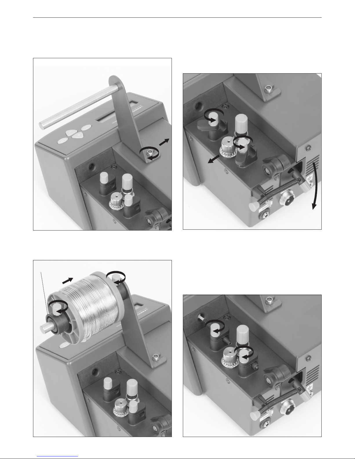
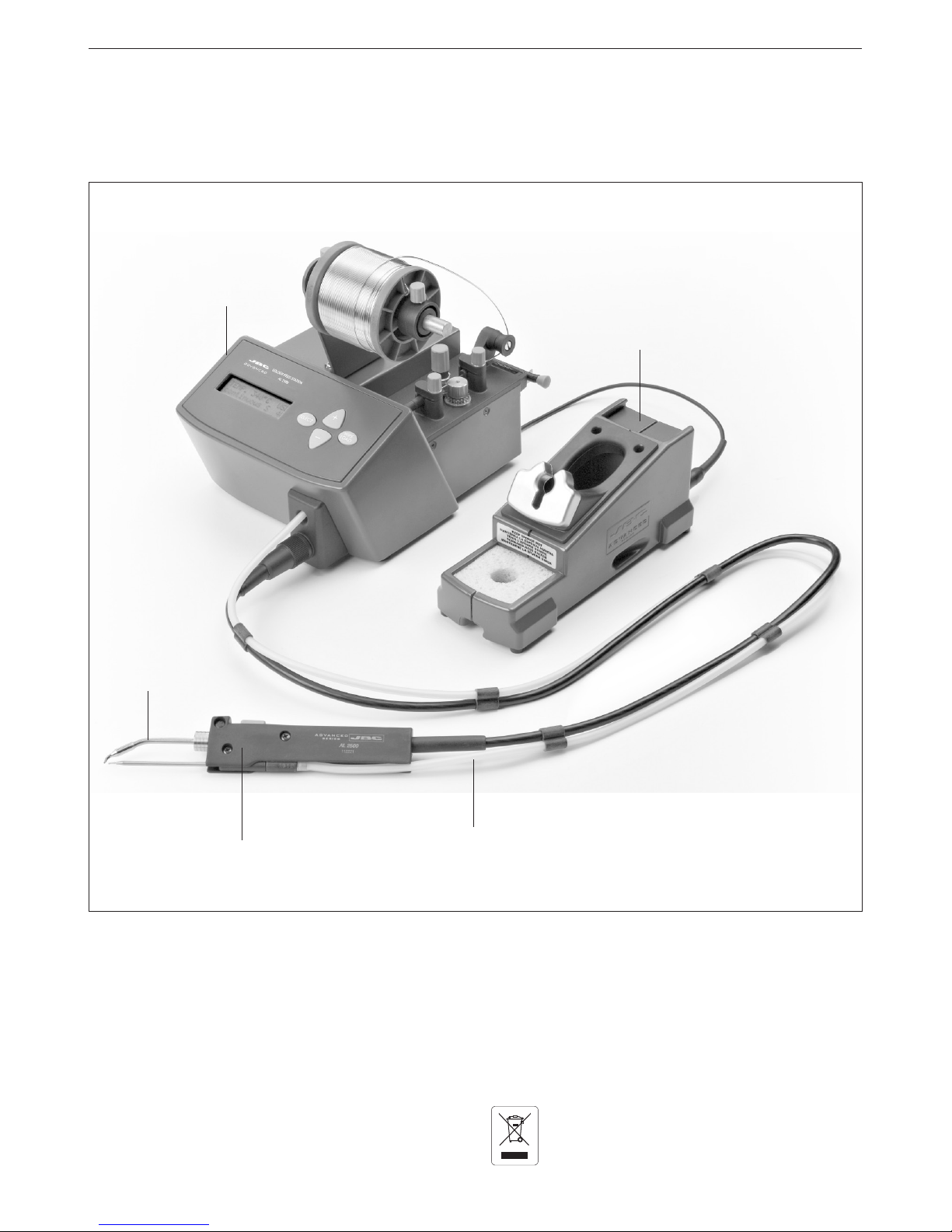
CLUTCH REGULATION
The dragging mechanism of the station has one
clutch A.
Its function is to allow the forwarding of the solder
threat when the station is working properly but also
avoid stall and or clugging situations when any
cause arises.
The dragging strengh must be adjusted with the
command A. If we rotate it the dragging strengh
is increased.
A
B
With command Bthe dragging system is tauten.
The more gap, the more strenght will be obtained.
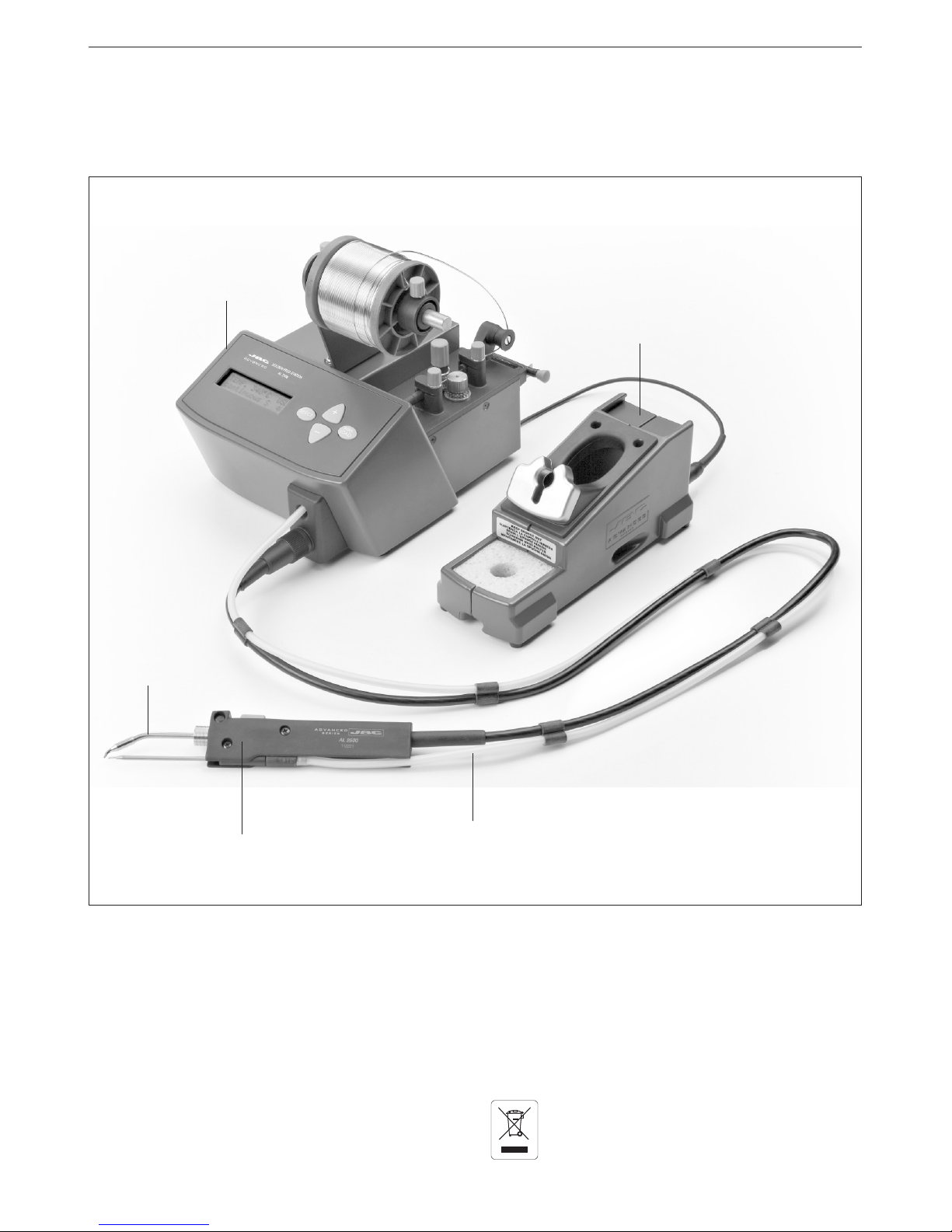
The station is ready to work.
In order to make a solder joint you only need to
press over the thread dragging button in the handle.
The programm of the station will allow you to modify
all the working parameters. You can display the
parameters with the SELECT key and modify them
with +and - keys.
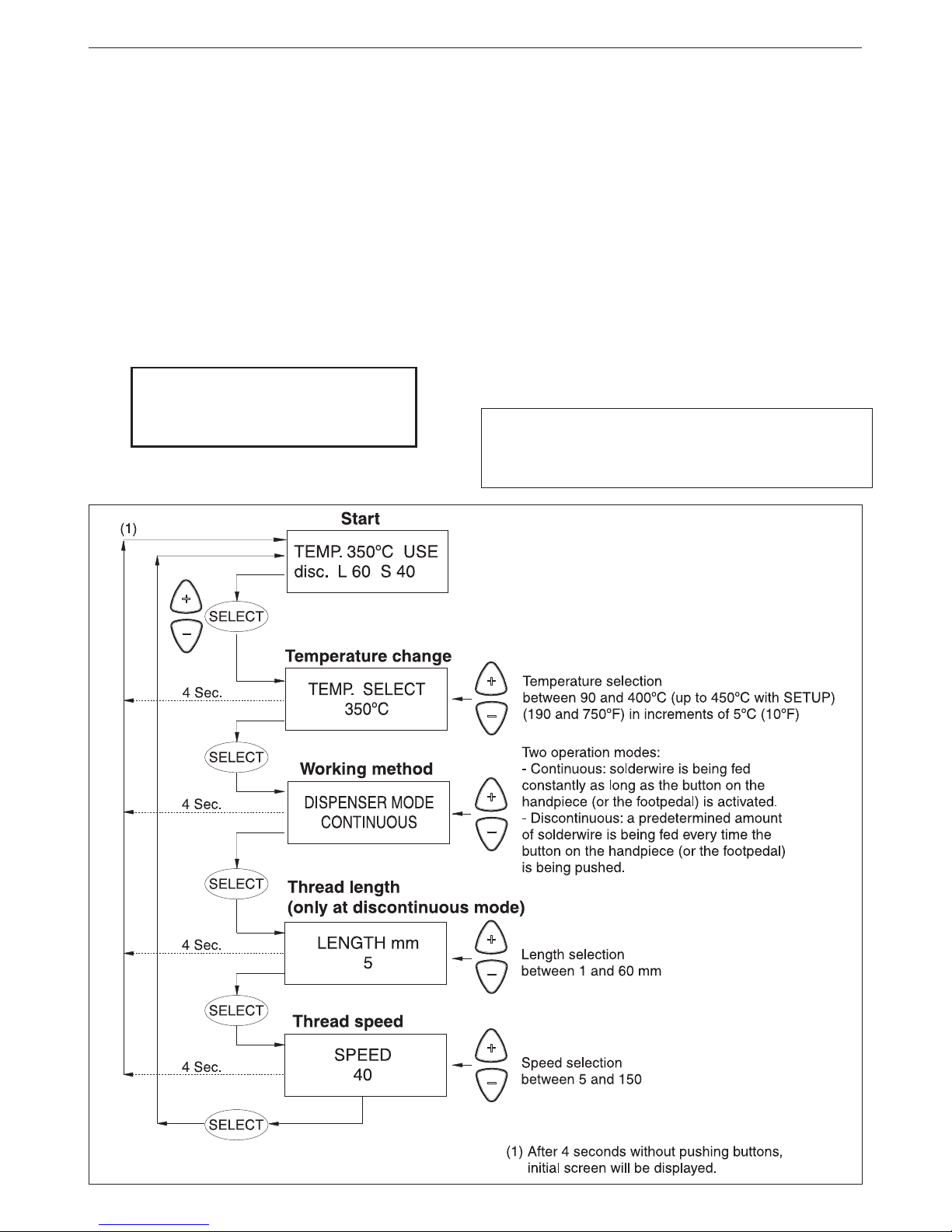
PROGRAMMING
Thesystemallowustomodifyandadjustthefollowing
working parameters directly:
- Temperature between 90 and 400ºC (up to 450ºC
with SETUP).
- Working mode.
- Length thread.
- Speed advance thread.
In order to modify the initial installation parameters
and have access to the counters, you must hold the
SELECT key for 3 seconds.
You will find the operation diagrams are on the
following pages.
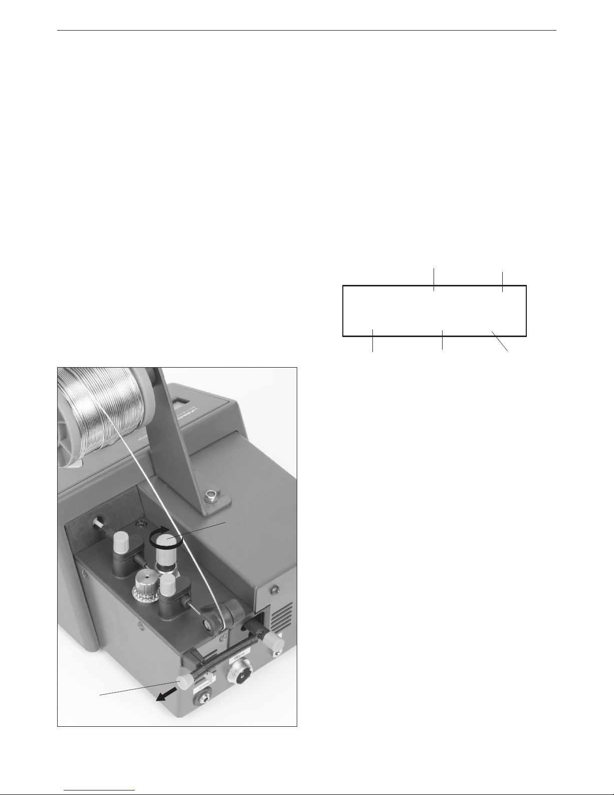
STATION DISPLAY
There are 4 tool status:
USE (Use). The tool is ready to work.
STD (Stand). The tool is placed in the stand but still
not in the sleep mode.
SLP (Sleep). The tool is in the sleep mode in the
stand, its temperature has dropped till the sleep
temperature.
OL. The power circuit is overheated. The power is
temporarily not supplied.
TEMP. 230ºC USE
disc. L 10 S 11
Tool temperature Tool status
Length thread Speed
Working method
ERROR MESSAGES
No cartridge/tool
Either no tool is connected with the correct cartridge
or the heating element of the cartridge is open.
Wrong tool
The tool which is connected is not valid.
Shortcircuit
The cartridge is in shortcircuit
System stopped by overload (100ºC / 210ºF)
The station has reached a dangerous temperature
and the station stops.
WARNING MESSAGES
Overload (85ºC /185ºF)
When the temperature of the station is close to its
maximum limit, a warning appears for 2 seconds
each 8 seconds as long the station is not cooled
down. The station does not stop.