jbc PHSK-B User manual

日本語 33
Deutsch 23
Español 13
English 3
Page
IR Preheater Set
Ref. PHS-KB
www.jbctools.com
中文 43

2 3
Ref. CLMB-A
2 32 3
Packing List
The following items should be included:
Heater Unit Console
Power Cord .............................................. 1 unit
Ref. 0009417 (100V/120V)
0009401 (230V)
Thermocouple ............ 1 unit
Ref. PH218
Kapton Tape ................. 1 unit
Ref. PH217
IR Preheater Support ........................... 1 unit
Ref. PHS-SA
Manual ........................... 1 unit
Ref. 0017155
ww w. jbc to ols .c om
Ref. PHS-KB
IR Preheater Set
IR Preheater ....................................................................................................................................... 1 unit
Ref. PHS-1B (120V)
PHS-2B (230V)
PHS-9B (100V)
www.jbctools.com

4 54 54 5
Features
Console socket
connection Pedal socket connection (optional)
Heating Area
Mains
input Mains
switch
Fixing brackets
for PHS-SA
IR Preheater Support
Heater Unit
Console Control Unit
Auxiliary Thermocouple (Type K)
Input
Thermocouple
(Type K)
USB-B connector to PC:
- Update the Control Unit
software
Zone B
Zone A
IR Preheater Support
For fixing
irregular
shaped
PCBs to the
support.
For fixing identical PCBs
in the same position.
Slot Clamps
Height Adjustment
The PHS-SA allows adjustment for 3 heights between the board and the Heating Area.
For PCBs of 0.8-2.4mm thick.
For PCBs of 2.4-6mm thick.
· Low level
· High level
· Medium level
For PCBs over 6mm thick.
28mm
50mm
70mm
www.jbctools.com

6 7
6 76 7
Profiles by Temperature
Why Infrared? The most efficient technology for PCB preheating
Operation
The usual way to run a profile is using the Thermocouple (TC) connected to the Control Input of the
console. JBC offers 3 predefined profiles (JBCset) and 10 profiles ready for you to personalize.
JBCset profiles
There are 3 profiles predefined by JBC: A, B and C. The difference between them is the number
of steps: 2, 3 or 4. The thicker your PCB is and the more layers it contains, the more steps are
needed to obtain a gradual warming.
These profiles are not modifiable but they can be used as a template to create your own profiles.
JBCset A
2 steps
JBCset B
3 steps
JBCset C
4 steps
This is the most advanced, efficient and cost-effective method to preheat PCBs in any soldering
job or rework job. The low thermal mass of the infrared element gives outstanding control of the
heat output and the process temperature. This technology provides fast response, high heating
rates and uniform heating that ensure the best results.
For repetitive jobs we recommend running profiles without the Thermocouple (TC). Once
any profile has been run to the end, the system has all the process data which you can save.
Once it is saved, you can run this profile without connecting the Thermocouple (TC). The
heating process will the same as long as the same working conditions are respected.
User profiles
You can create your own profiles from the JBCset profiles. On the work screen of the profile,
press the Enter button and choose the option Edit profile.
Power Mode
The unit works at the selected power during the defined time. These parameters can be modified
from the work screen by pressing the Enter button and the Edit parameters menu.
To see the current temperature you must plug the Thermocouple (TC) into the Control connector.
PCB
reference
specifications:
FR4 1,6mm thick
and 2 layers.
FR4 2,2mm thick
and 6 layers.
FR4 1,6mm thick
and 6 layers.
Profiles set using the low position of the PHS-SA Support (28 mm in height between the PCB and the heating area).
Recommended Guidelines
1. Place the Thermocouple (TC) as near as possible to the component being worked on.
2. If there are any sensitive components, use the Auxiliary Thermocouple as protection.
You can select the protection temperature in Station settings. If the selected temperature is rea-
ched, the Heater Unit will stop the process and a warning message will be shown.
3. IPC* does not recommend exceeding ramp-up rates over 3 - 4 °C / sec (5 - 7 °F / sec) so as to
reduce the risk of thermal stress on the PCB.
* IPC was founded in the U.S. in 1957 as the Institute for Printed Circuits.
Fix the TC with Kapton Tape
Auxiliary Thermocouple (TC)
www.jbctools.com

8 98 98 9
Display Control
www.jbctools.com

10 11
10 1110 11
Safety
It is imperative to follow safety guidelines to protect health and prevent electric
shock, injury, fire or explosions.
- Do not use the units for any purpose other than PCB preheating. Incorrect use may cause fire.
- The power cord must be plugged into approved bases. Be sure that it is properly grounded
before use. When unplugging it, hold the plug, not the wire.
- The temperature of accessible surfaces may remain high after the unit is turned off. Handle with care.
- Do not leave the appliance unattended when it is on.
- Do not cover the ventilation grills. Heat can cause inflamable products to ignite.
- Use a “non residue” classified flux and avoid contact with skin or eyes to prevent irritation.
- Be careful with the fumes produced when soldering.
- Keep your workplace clean and tidy. Wear appropriate protective glasses and gloves when
working to avoid personal harm.
- Utmost care must be taken with liquid tin waste which can cause burns.
- This appliance can be used by children over the age of eight and also persons with reduced
physical, sensory or mental capabilities or lack of experience provided that they have been given
adequatesupervision or instruction concerning use ofthe appliance and understand thehazards
involved. Children must not play with the appliance.
- Maintenance must not be carried out by children unless supervised.
Specifications
IR Preheater Set
PHS-1KB /PHS-2KB / PHS-9KB
- Total weight: 4.9 kg (10.8 lb)
- Ambient Operating Temperature: 10-40ºC (50-104ºF)
PHS-1B 120V. Input 120V 50/60Hz Fuse 8A
PHS-2B 230V. Input 230V 50/60Hz Fuse 4A
PHS-9B 100V. Input 100V 50/60Hz Fuse 8A
- Weight: 2.9 kg (6.4 lb)
- Dimensions (Heater Unit): 173 x 282 x 41 mm
- Maximum Power: 500W
- Heating Area: 65 x 135mm (1 zone) 130 x 135mm (2 zones)
- Temperature Range: 50-250°C (120-482ºF)
- Temperature Measurement: Thermocouple type K
- JBCset temperature profiles: 3 profiles ( 2, 3 or 4 steps)
- User Profiles: 20 (up to 6 steps for each)
- Maximum work time: 600 min or indefinite
PHS-SA
- Weight: 2 kg (4.4 lb)
- Dimensions: Low position 267 x 259 x 75 mm / High position 267 x 259 x 95 mm
- ESD safe connector
Complies with CE standards
ESD protected housing “skin effect”
www.jbctools.com

12 13
Ref. CLMB-A
12 13
Composición
Los siguientes artículos deberían estar incluidos:
12 13
Heater Unit
Unidad calefactora
Console
Consola
Power Cord
Cable de red ............................................. 1 unit
Ref. 0009417 (100V/120V)
0009401 (230V)
Thermocouple
Termopar ...................... 1 unit
Ref. PH218
Kapton Tape
Cinta Kapton ................... 1 unit
Ref. PH217
IR Preheater Support
Soporte para PCBs ................................. 1 unit
Ref. PHS-SA
Manual ........................... 1 unit
Ref. 0017155
ww w. jbc to ols .c om
IR Preheater Set
IR Preheater
Precalentador por infrarrojos ........................................................................................................... 1 unit
Ref. PHS-1B (120V)
PHS-2B (230V)
PHS-9B (100V)
PHS-KB
www.jbctools.com

14 1514 15
Características
Conexión
a la Consola Conexión para pedal (opcional)
Zona B
Área calefactora
Zona A
Unidad de Control
Entrada
de Red Conector
de Red
Fijadores para el
soporte PHS-SA
Entrada para Termopar Auxiliar
(Tipo K)
Termopar
(Tipo K)
Conector USB-B para PC:
- Actualizar el programa
de la Unidad de control
Para fijar en
el soporte
los PCBs
de forma
irregular.
Abrazaderas
Ajuste de altura
Heater Unit
Unidad calefactora
Console
Consola
IR Preheater Support
Soporte para Precalentador IR
El soporte PHS-SA permite ajustar 3 alturas entre el PCB y el área calefactora.
Para PCBs de espesores
entre 0,8 y 2,4mm.
Para PCBs de espesores
entre 2,4 y 6mm.
· Nivel Bajo
· Nivel Medio
Para fijar PCBs idénticos
en la misma posición.
· Nivel Alto
Para PCBs de espesores
superiores a 6mm.
28mm
50mm
70mm
14 15
www.jbctools.com

16 1716 17
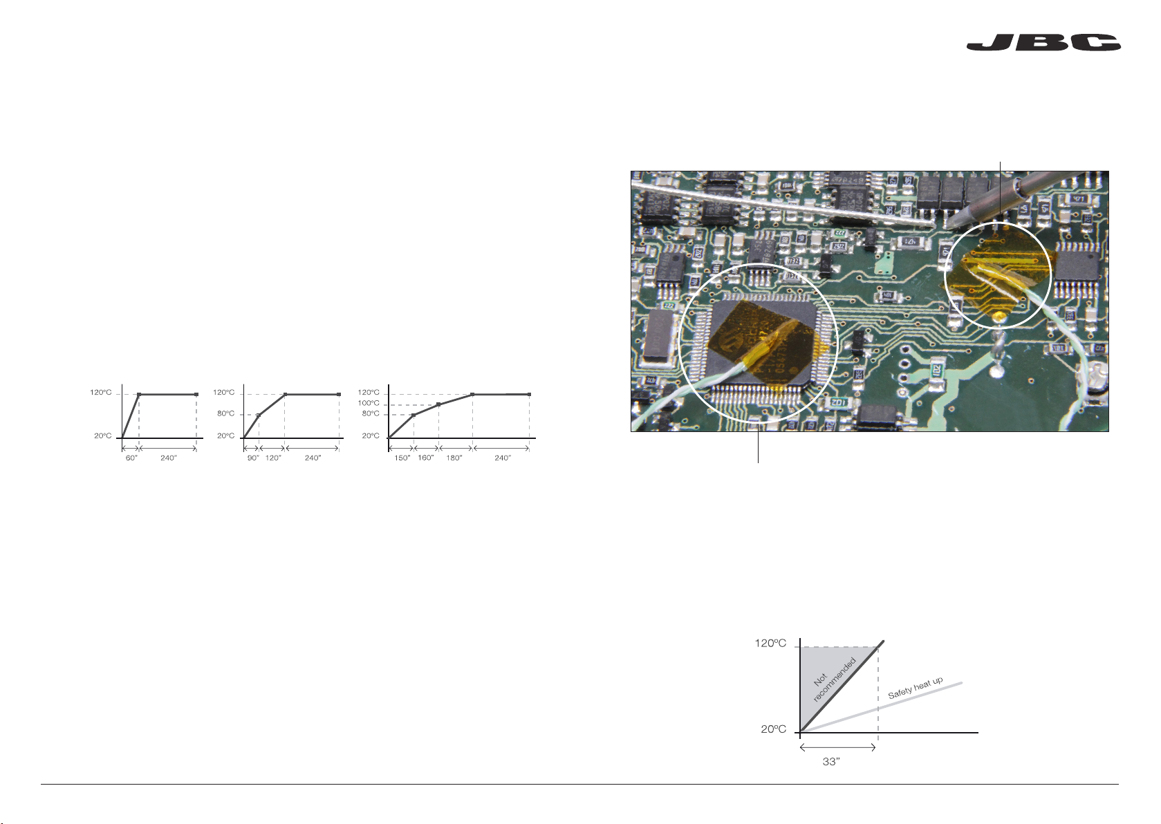
Temperature profiles (Perfiles por Temperatura)
Funcionamiento
JBCset A
2 pasos
JBCset B
3 pasos
JBCset C
4 pasos
Recomendaciones
Cinta Kapton para fijar el Termopar en el PCB
Recomendamos que para trabajos repetitivos, se ejecuten los perfiles sin Termopar: Una
vez un perfil cualquiera se ha ejecutado hasta el final, el sistema dispone de todos los datos
del proceso y pregunta si se desea salvar. En caso afirmativo se podrá ejecutar ese perfil sin
tener el termopar conectado. El proceso de calentamiento será idéntico siempre que se
respeten las mismas condiciones de trabajo.
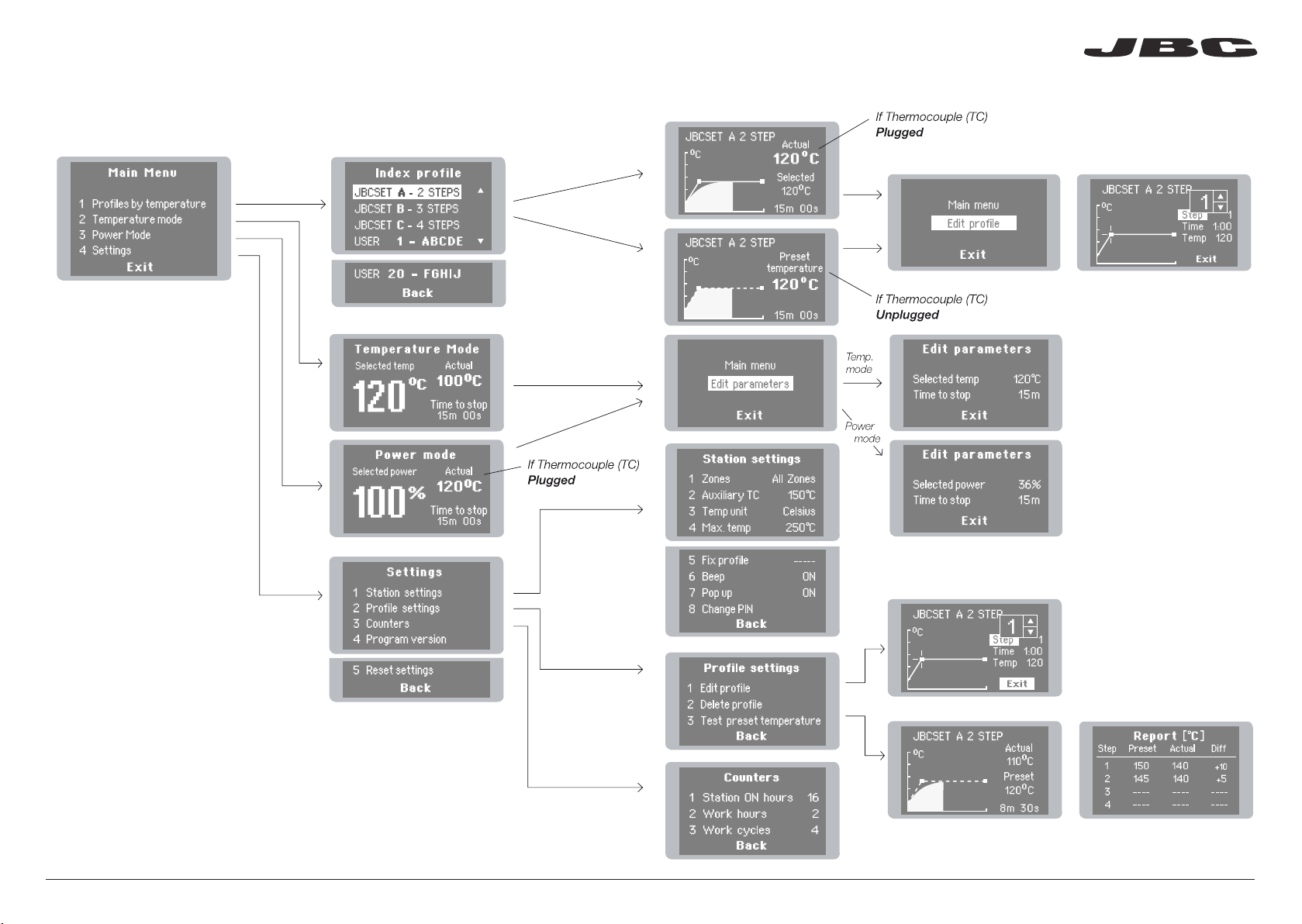
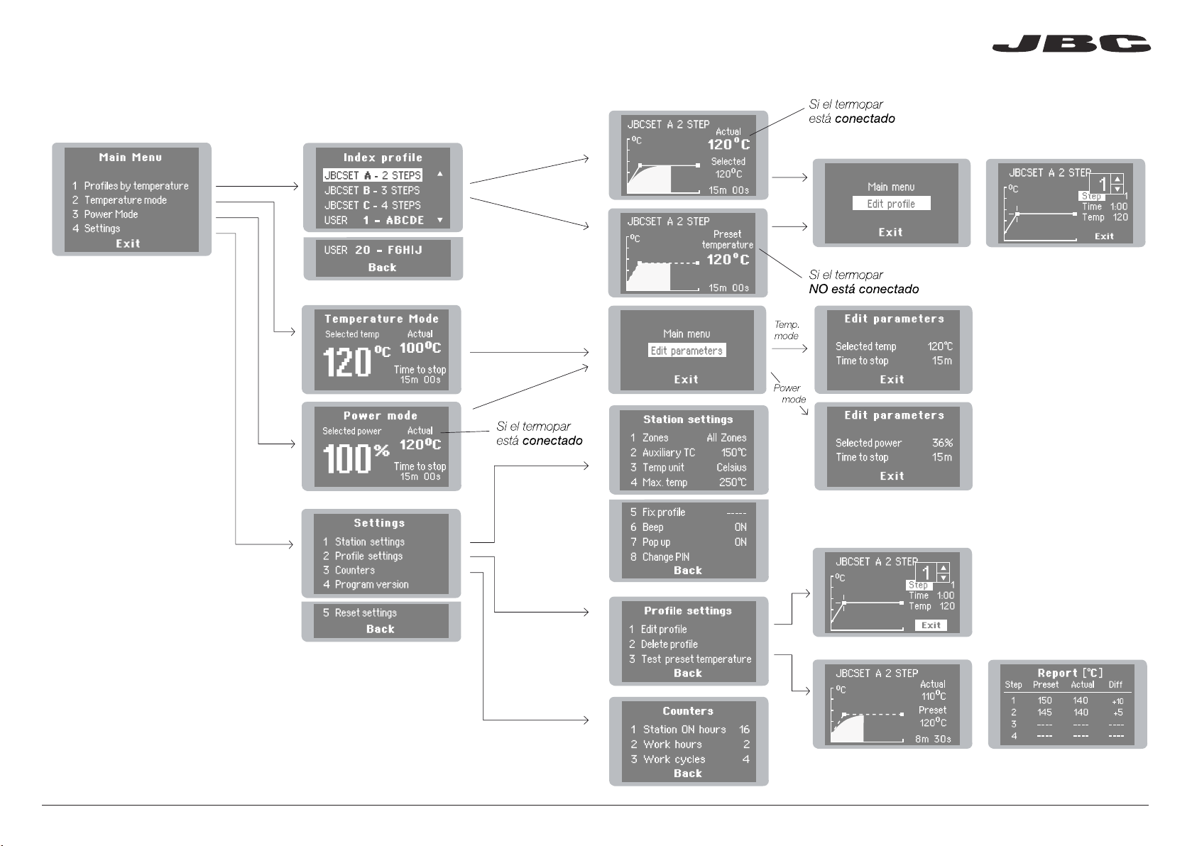
El modo usual de ejecutar un perfil es utilizando el Termopar (TC) en el conector de Control. JBC
le ofrece 3 perfiles predefinidos (JBCset) y 10 perfiles listos para personalizar (User Profiles).
JBCset profiles (Perfiles JBCset)
Hay 3 perfiles predefinidos por JBC: A, B y C. La diferencia entre ellos es el número de pasos:
2, 3 o 4. Cuanto más grueso sea su PCB y más capas contenga, más pasos serán necesarios
para obtener un calentamiento uniforme y progresivo.
Estos perfiles no son modificables pero pueden ser usados como plantilla para crear sus
propios perfiles (User Profiles).
User Profiles (Perfiles de Usuario)
Puede crear sus propios perfiles a partir de los perfiles JBCset. Desde la pantalla de trabajo del
perfil, apriete el botón Enter y elija la opción Edit profile.
PCBs y
condiciones
de referencia:
FR4 de espesor
1,6mm y 2 capas. FR4 de espesor
2,2mm y 6 capas.
FR4 de espesor
1,6mm y 6 capas.
¿Por qué Infrarrojos? La tecnología más eficiente para precalentar PCBs
Es el método más avanzado, eficiente y rentable para precalentar PCBs en cualquier trabajo de
soldadura o reparación. La poca masa térmica del elemento infrarrojo proporciona un control ex-
cepcional del calor y de la temperatura del proceso. Esta tecnología ofrece una respuesta rápida,
altas tasas de calor y un calentamiento uniforme que garantiza los mejores resultados.
Power Mode (Modo de potencia)
La unidad funciona a la potencia seleccionada durante el tiempo establecido. Estos parámetros
pueden ser modificados desde la pantalla de trabajo apretando el botón Enter y accediendo al
menu Edit parameters.
Si desea ver la temperatura actual debe conectar el Termopar en el conector de Control.
Perfiles realizados utilizando la posición baja del soporte PHS-SA (28 mm de altura entre el PCB y el área calefactora):
1. Coloque el Termopar tan cerca como sea posible del componente a trabajar.
2. Si hay algún componente sensible, use el Termopar Auxiliar como protección.
Puede seleccionar la temperatura de protección en el menú Station settings. Si la temperatura
llega a la establecida, se interrumpirá el proceso y mostrará un warning.
3. IPC* no recomienda exceder tasas de rampas por encima de los 3 - 4 °C / seg (5 - 7 °F / seg)
con el fin de reducir el riesgo de estrés térmico en los PCBs.
* IPC se fundó en USA en 1957 con el nombre de Institute for Printed Circuits.
Termopar Auxiliar (TC)
16 17
www.jbctools.com

18 1918 19
Pantallas de control
18 19
www.jbctools.com

20 21
20 21
Seguridad
- No utilice la unidad para otros fines que no sea el precalentamiento de PCBs. El uso incorrecto
puede causar fuego.
- El cable de red debe enchufarse en bases homologadas. Asegúrese de que está conectado a
tierra antes correctamente antes de su uso.
- La temperatura de las superficies accesibles puede ser alta incluso cuando la unidad está apagada.
Manipule con cuidado.
- No deje el aparato desatendido cuando esté en funcionamiento.
- No cubrir las rejillas de ventilación.
- El calor puede causar que los productos inflamables se enciendan aunque no estén a la vista.
- Tenga cuidado con los restos de estaño líquido. En contacto con la piel, puede causar quemaduras.
- Utilice un flux clasificado como “non residue” y evite el contacto con la piel y los ojos para evitar
que se irriten.
- Tenga cuidado con el humo producido al trabajar.
- Mantenga su lugar de trabajo limpio y ordenado. Use gafas y guantes de protección adecuados.
Así evitará cualquier daño.
- Este aparato puede ser utilizado por personas a partir de 8 años o más y también por aquellas
personas con movilidad reducida o capacidades físicas, sensoriales o mentales limitadas o
con falta de experiencia y conocimientos siempre y cuando reciban supervisión o instrucciones
relativas al uso del aparato de una manera segura y entiendan los riesgos involucrados. Los
niños no deben jugar con el aparato. La limpieza y el mantenimiento no se deberá realizar por
niños sin supervisión.
- Cualquier mantenimiento de las unidades sólo podrá ser realizado por un servicio técnico oficial.
Especificaciones
IR Preheater Set · Set Precalentador de Infrarrojos
PHS-1KB /PHS-2KB / PHS-9KB
- Peso total: 4,9 kg (10.8 lb)
- Temperatura de trabajo ambiente: 10-40ºC (50-104ºF)
PHS-1B 120V. Entrada 120V 50/60Hz Fusible 8A
PHS-2B 230V. Entrada 230V 50/60Hz Fusible 4A
PHS-9B 100V. Entrada 100V 50/60Hz Fusible 8A
- Peso total: 2,9 kg (6.4 lb)
- Dimensiones Unidad Calefactora: 173 x 282 x 41 mm
- Potencia máxima: 500W
- Área calefactora: 65 x 135 mm (1 zona) / 130 x 135 mm (2 zonas)
- Rango de temperatura: 50-250°C (120-482ºF)
- Medición de temperatura: Termopar Tipo K
- Perfiles predefinidos por JBC (JBCset): 3 perfiles (2, 3, 4 pasos)
- Perfiles de usuario: 20 (hasta 6 pasos para cada uno)
- Tiempo de trabajo máximo: 600 min o indefinido
PHS-SA
- Peso: 2 kg (4.4 lb)
- Dimensiones: Nivel bajo 267 x 259 x 75 mm / Nivel alto 267 x 259 x 95 mm
- Conector de seguridad ESD
Cumple con las normativas CE
Protección ESD “skin effect”
Es necesario seguir estas directrices de seguridad para proteger su salud y
prevenir cualquier choque eléctrico, heridas, fuego o explosiones.
20 21
www.jbctools.com

22 23
Inhalt
Die folgenden Teile sollten in dem Paket enthalten sein:
Ref. CLMB-A
22 2322 23
Heater Unit
Vorheizgerät
Console
Konsole
Power Cord
Netzkabel ............................................. 1 Einheit
Ref. 0009417 (100V/120V)
0009401 (230V)
Thermocouple
Thermoelement ...... 1 Einheit
Ref. PH218
Kapton Tape
Kaptonband .............. 1 Einheit
Ref. PH217
IR Preheater Support
Halter für IR-Unterheizung ................ 1 Einheit
Ref. PHS-SA
Handbuch ................ 1 Einheit
Ref. 0017155
ww w. jbc to ols .c om
IR Preheater Set
IR Preheater
IR- Unterheizung ............................................................................................................................ 1 Einheit
Ref. PHS-1B (120V)
PHS-2B (230V)
PHS-9B (100V)
PHS-KB
www.jbctools.com

24 25
Eigenschaften
Steckanschluß für
Konsole Steckanschluß für Pedal
Heizzone
Netzanschluss Netzschalter
Befestigungselemente
für PHS-SA Halter für
IR-Unterheizung
Heater Unit
Vorheizgerät
Console
Konsole
Steuereinheit
Eingang für Hilfsthermoelement
(Typ K)
Thermoelement
(Typ K)
USB-B Anschluss zum PC:
- Zum aktualisieren der
Steuereinheits-software
Zone B
Zone A
IR Preheater Support
Halter für IR-Unterheizung
Verwendet, um
unregelmäßig
geformte
Leiterplatten
im Halter zu
fixieren.
Verwendet, um identische
Leiterplatten in der selben
Position zu fixieren
Schlitzklemmen
Höhenverstellung
Der PHS-SA ermöglicht es drei unterschiedliche Höhen zwischen PCB und Heizfläche einzustellen.
Für Leiterplatten mit Dicken
zwischen 0,8 und 2,4 mm.
Für Leiterplatten mit Dicken
zwischen 2,4 und 6 mm.
· Untere Position
· Obere Position:
· Mittel Position
Für Leiterplatten mit Dicken
über 6 mm.
28mm
50mm
70mm
24 2524 25
www.jbctools.com

26 27
Temperature Profiles (Temperaturprofile)
Warum Infrarot? Die effizienteste Technologie für die PCB Vorheizung
Betrieb
Der übliche Weg, um ein Profil ausführen zu lassen, ist die Verwendung des Thermoelements (TC),
das mit dem Steuereingang der Konsole verbunden wird. JBC bietet drei vordefinierte Profile (JBC
set) und 10 frei zu definierende Profile an.
JBCset Profiles (JBC vordefinierte Profile)
Es gibt 3 vordefinierte JBC Profile: A, B und C. Der Unterschied zwischen ihnen ist die Anzahl
der Stufen: 2, 3 oder 4. Je dicker Ihre Leiterplatte ist und je mehr Schichten enthalten sind, desto
mehr Stufen sind notwendig, um eine allmähliche Erwärmung zu erhalten.
Diese Profile können nicht geändert werden, aber sie können als Vorlage verwendet werden, um
eigene Profile zu erstellen.
JBCset A
2 Stufen
JBCset B
3 Stufen
JBCset C
4 Stufen
Dies ist die fortschrittlichste, effizienteste und kostengünstigste Methode, um Leiterplatten für jede
beliebige Lötarbeit oder bei Reparaturarbeiten vorzuheizen. Die geringe thermische Masse des
Infrarotelementes bietet eine hervorragende Kontrolle der Heizleistung und der Prozesstempera-
tur. Diese Technologie bietet schnelle Reaktionszeiten, hohe Erwärmungsraten und gleichmäßige
Erwärmung, was beste Ergebnisse sicherstellt.
Für sich wiederholende Arbeiten empfehlen wir Profile ohne Thermoelement (TC) laufen zu
lassen. Sobald ein Profil bis zum Ende ausgeführt wurde, hat das System alle Prozessdaten
und fragt, ob Sie sie speichern möchten. Wenn das der Fall ist, dann können Sie arbeiten ohne
dass das Thermoelement angeschlossen ist. Der Erwärmungsvorgang wird identisch sein,
solange die gleichen Arbeitsbedingungen eingehalten werden.
User profiles (Benutzerprofile)
Basierend auf den JBC Profilen können Sie Ihre eigenen Profile erstellen. Auf dem Bildschirm
drücken Sie die Enter-Taste und wählen die Option Enter Profile.
Power Mode (Energie-Modus)
Das Gerät arbeitet mit der gewählten Leistung während der definierten Zeit. Diese Parameter können
vom Bildschirm aus durch drücken der Enter-Taste und dem Edit Parameters Menu geändert werden.
Um die aktuelle Temperatur zu sehen, müssen Sie das Thermoelement (TC) anschliessen.
PCB
Referenz
Spezifikationen
FR4 1,6 mm dick
und 2 Schichten. FR4 2,2 mm dick
und 6 Schichten.
FR4 1,6 mm dick
und 6 Schichten.
Profil-Einstellungen (settings) unter Verwendung der niedrigen Position des PHS-SA Halters (28 mm position).
Empfehlungen
1. Bringen Sie das Thermoelement so nah wie möglich bei der zu bearbeitenden Komponente an.
2. Wenn es ein besonders empfindliches Element auf der Leiteplatte gibt, benutzen Sie ein
zusätzliches Hilfsthermoelement um dieses Bauteil zu schützen.
Sie können die Schutztemperatur in dem Menu Station Settings auswählen. Wenn die gewählte
Temperatur erreicht ist, wird das IR-Vorheiz-System den Prozess stoppen und eine Warnmeldung
angezeigen.
Kapton-Band, um das Thermoelement (TC) auf der Leiterplatte zu fixieren
3. IPC* empfiehlt Anstiegsraten von 3 - 4 °C/s nicht zu überschreiten, um die Gefahr von
thermischen Stress auf der Leiterplatte zu reduzieren.
* IPC wurde in den USA im Jahr 1957 mit dem Namen Institute for Printed Circuits (Institut für Leiterplatten) gegründet.
Hilfsthermoelement (TC)
26 2726 27
www.jbctools.com

28 29
Menu-Steuerung
28 2928 29
www.jbctools.com

30 31
Sicherheit
- Setzen Sie das Gerät nicht für einen anderen Zweck als zum Vorwärmen von PCB´s ein. Falsche
Verwendung kann Brand verursachen.
- Das Netzkabel darf nur in zugelassenen Steckdosen eingesteckt werden. Achten Sie vor der
Verwendung darauf, das die Steckdose ordnungsgemäss geerdet ist.
- Die Temperatur von zugänglichen Oberflächen kann hoch sein, auch wenn das Gerät ausges
chaltet ist. Vorsicht beim Umgang.
- Lassen Sie das Gerät nicht unbeaufsichtigt, wenn es in Betrieb ist.
- Verdecken Sie nicht die Lüftungsgitter.
- Hitze kann dazu führen, brennbare Produkte zu entzünden, auch wenn diese nicht sichtbar sind.
- Seien Sie vorsichtig mit den Überresten von flüssigem Zinn. Bei Kontakt mit der Haut, kann es zu
Verbrennungen führen.
- Verwenden Sie ein “non residue” eingestuftes Flussmittel und verhindern Sie Berührung mit der
Haut oder den Augen, um Irritationen zu vermeiden.
- Seien Sie vorsichtig mit dem beim Löten erzeugten Lötrauch.
- Halten Sie Ihren Arbeitsplatz sauber und ordentlich. Tragen Sie eine geeignete Schutzbrille und
Handschuhe bei der Arbeit, um Verletzungen zu vermeiden.
- Dieses Gerät kann von Kindern ab 8 Jahren und älter und von Personen mit eingeschränkten
physischen, sensorischen oder geistigen Fähigkeiten oder mit mangelnder Erfahrung
und Wissen benutzt werden, wenn eine angemessene Aufsicht oder ausführliche Anleitung
zur sicheren Benutzung des Gerätes erfolgte und die damit verbundenen Gefahren verstanden
wurden Kinder dürfen nicht mit dem Gerät spielen. Reinigung und Wartung dürfen nicht von
Kindern ohne Beaufsichtigung eines Erwachsenen durchgeführt werden.
- Die Wartung der Geräte darf nur von einem After-Sales Service durchgeführt werden.
Es ist zwingend notwendig den Sicherheitsrichtlinien zu folgen, um die
Gesundheit zu schützen und Stromschlägen, Verletzungen, Brand oder
Explosionen vorzubeugen.
Technische Daten
IR Preheater Set · Infrarot-Unterheizungsset
PHS-1KB /PHS-2KB / PHS-9KB
- Gesamtgewicht: 4.9 kg (10.8 lb)
- Umgebungstemperatur: 10-40ºC (50-104ºF)
PHS-1B 120V. Eingang 120V 50/60Hz Sicherung 8A
PHS-2B 230V. Eingang 230V 50/60Hz Sicherung 4A
PHS-9B 100V. Eingang 100V 50/60Hz Sicherung 8A
- Gesamtgewicht: 2,9 kg (6.4 lb)
- Maximale Leistung: 500W
- Heizfläche: 65 x 135 mm (1 Zone) / 130 x 135 mm (2 Zonen)
- Temperaturbereich: 50 bis 250 ºC (120-482ºF)
- Temperaturmessung: Thermoelement Typ K
- 3 JBCset Temperaturprofile
- Bis zu 20 Benutzerprofile (bis zu 6 Schritte für jedes Profil)
- Maximale Arbeitszeit: 600 min oder unbegrenzt
PHS-SA
- Masse: 2 kg (4.4 lb)
- Abmessungen: Untere Position 267 x 259 x 75 mm / Obere Position 267 x 259 x 95 mm
- ESD-gerechter Anschluss
Entspricht den CE-Normen
ESD-geschütztes Gehäuse “Skin-Effekt”
30 3130 31
www.jbctools.com

32 33
付属品リスト
梱包内容:
Ref. CLMB-A
32 3332 33
Heater Unit
ヒーターユニット
Console
プレヒーター操作盤
Power Cord
電源コード .................................................... 1 個
Ref. 0009417 (100V/120V)
0009401 (230V)
Thermocouple
サーモカップル ................ 1 個
Ref. PH218
Kapton Tape
カプトンテープ ................... 1 個
Ref. PH217
IR Preheater Support
プリント基板
サポート台 ................................................... 1 個
Ref. PHS-SA
マニュアル ........................ 1 個
Ref. 0017155
ww w. jbc to ols .c om
IR Preheater
ヒーターセット ....................................................................................................................................... 1 個
Ref. PHS-1B (120V)
PHS-2B (230V)
PHS-9B (100V)
IR Preheater Set
PHS-KB
www.jbctools.com

34 35
プレヒーター
操作盤接続 ペダルソケット接続 (オプション)
加熱部分
電源
接続
メインスイッチ
PHS-SAサポート台の
ための固定ブラケット
Console
プレヒーター操作盤
コントロールユニット
補助サーモカップル (Kタイプ)
インプット
サーモカップル
(Kタイプ)
USB-B 接続
- コントロールユニットのソフ
トウェアを更新する
Bゾーン
Aゾーン
各部の名称
Heater Unit
プレヒーターユニット
IR Preheater Support
プリント基板サポート台
PCBの不揃
いな角度を
調整するた
めの金具
同じ位置で同じPCBを
調整するため
固定金具
PCBs 薄さ0.8-2.4mm
PCBs 薄さ2.4-6mm
PCBs 薄さ6mm 以上
高さ調節
PCBサポート台により、ボードと加熱部分の間で3段階の高さ調節ができます。
· 低位置
· 高位置
· 中位置
28mm
50mm
70mm
34 3534 35
www.jbctools.com

36 37
1. サーモカップル(TC)を作業するパーツのできるだけ近くに位置させる。
2. とても敏感なパーツの場合には保護のために補助サーモカップルをお使いください。ステーション
セッティングで保護温度を選択してください。
選択された温度に達したら、PHヒーターユニットはプロセスをストップし、警告メッセ−ジが表示され
るでしょう。
サーモカップルを固定するためのカプトンテ−プ
3. プリント基板上の温度摩擦のリスクを少なくするため、IPC*は 3 - 4 °C / 秒(5 - 7 °F / 秒)以上の
速さで上昇するのはお勧めしません。
* IPC はプリント基板の研究所として1957年にアメリカ合衆国で設立されました。
補助サーモカップル (TC)
Temperature Profiles (温度によるプロファイル)
なぜ赤外線なのか。PCBsプレヒーティングに最適なテクノロジーだからです。
使用方法
プロファイルの通常の使用方法はサーモカップル(TC)がプレヒーター操作盤のコントロールインプッ
トに接続されている状態での使用になります。JBCは予め3つの定義付けされたプロファイル(JBCセ
ット)と個人に合わせて設定できる10のプロファイルを提供します。
JBCset Profiles (JBCセットプロファイル)
JBCによって予め定義された3つのプロファイル:A、B、C。3つの違いはステップの数:2、3、4。
PCBsが厚めなほどステップが必要になります。
JBCセット A
2 ステップ
JBCセット B
3 ステップ
JBCセット C
4 ステップ
あらゆるタイプの半田ごて作業または、再作業において、PCBsを予め暖めておくのに最も進化した、有
効で、費用効率の高い方法です。赤外線により暖められた小さな塊が熱放出とプロセス温度の調整を
顕著にします。この技術は迅速なレスポンス、高度な加熱速度、加熱の一様化により、最良な結果を
もたらします。
繰り返す作業のためにサーモカップル(TC)なしで、プロファイルを作動させるようお勧めします。
一度、どれかのプロファイルで最後まで作動させると、システムは保存したプロセスデータを保有
しています。一度保存されたら、サーモカップルを接続しなくてもそのプロファイルを作動させるこ
とができます。加熱プロセスは同じ作動環境が維持されていれば、同様に作動します。
User Profiles (ユーザープロファイリング)
JBCセットプロファイルからお客様自身のプロファイルを作っていただくことができます。作業スク
リーンで、Enterボタンを押し、プロファイルを編集するオプションを選択してください。
Power Mode (パワーモード)
ユニットは定義された時間内に選択されたパワーで作動します。このパラメーターはパラメーターメニ
ューのEnterとEditボタンを押して、作業スクリーンから修正することができます。
現時点の温度を見るためにサーモカップル(TC)をコントロール接続に差し込まなければなりません。
PCBs
参考仕様 : FR4 厚さ1,6mm 2層FR4 厚さ2,2mm 6層FR4 厚さ1,6mm 6層
プロファイルはPHS-SAプリント基板サポート台(PCBsと加熱部分の間の高さが28mm)低位置で使用されるようセットされています。
推奨される使用基準
36 3736 37
www.jbctools.com

38 39
コントロールディスプレイ
38 3938 39
www.jbctools.com
Other manuals for PHSK-B
1
Table of contents
Languages:
Other jbc Soldering Gun manuals