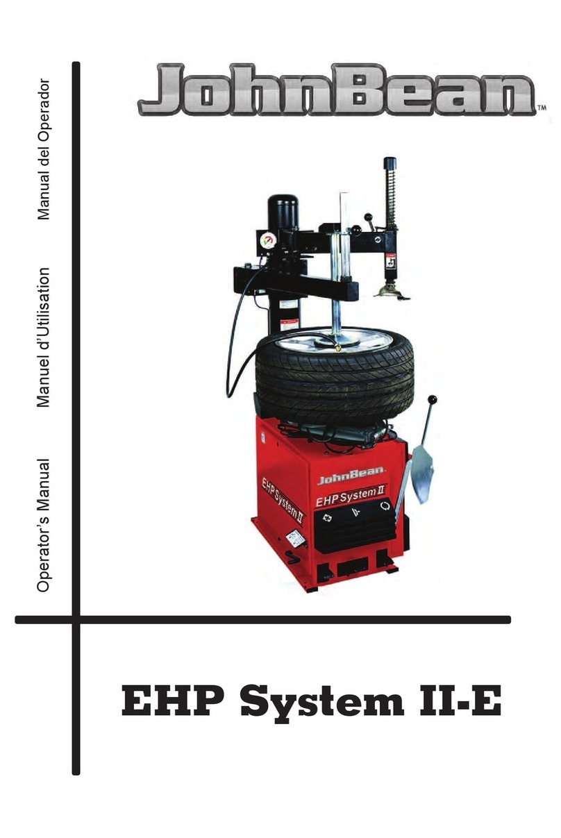
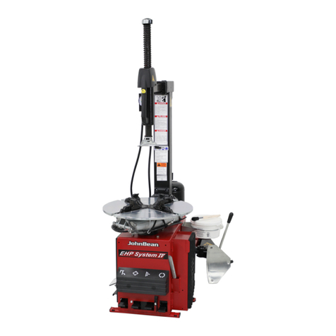
John Bean EHP System Series User manual

®
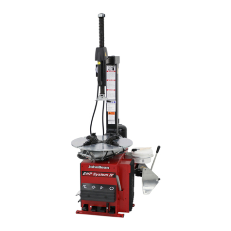
EHP System II
EHP System II E
High Performance Tire Changer
Operation Instructions
ZEEWH512A03 Rev.G

- Page 2 -
®EHP System II / II E Tire Changer Operation Manual
UPDATING GUIDE
Revision C of 10/2007
Optional Accessorie code: ST4029448 Updatedat page 13
Revision D of 09/2009
New code for Accessories: at page 12, 13
Text added: at page 17
Revision D1 of 12/2009
Notes regarding documentation, added at page 3
Revision E of 02/2010
New Accessories for turntable Type II: added at page 13
Revision F of 03/2010
Accessories no more available removed at page
New Language: Franch added pages all
New Operator Manual Part Number changed in ZEEWH512A03
Revision G of 07/2010 PCN: 10G0100
Nozzle lance for bead seater system BS added pages 12, 26, 36, 38

- Page 3 -
®
EHP System II / II E Tire Changer Operation Manual
ENG -NOTES REGARDING DOCUMENTATION
FRA -NOTES SUR LA DOCUMENTATION
DEU -ANMERKUNGEN ZUR DOKUMENTATION
NOTE SULLADOCUMENTAZIONE - ITA
NOTAS SOBRE LA DOCUMENTACIÓN - SPA
NOTAS SOBRE A DOCUMENTAÇÃO - POR
ABB. DESCRIPTION CODE LANGUAGE
SIGLE DESCRIPTION CODE LANGUE
KENN. BESCHREIBUNG CODE SPRACHE
Operator’s Manual
OM Manuel de l’Opérateur ZEEW512A03 ENG-FRA
Betriebsanleitung
Spare Parts Booklet ENG-FRA-DEU
SP Liste des pièces détachées TEEW512A3
Ersatzteilliste ITA-SPA-POR
SIGLA DESCRIZIONE CODICE LINGUA
SIGLA DESCRIPCIÓN CÓDIGO IDIOMA
SIGLA DESCRIÇÃO CÓDIGO IDIOMA
Manuale Operatore
OM Manual de Operador ZEEW512A03 ENG-FRA
Manual do Operador
Libretto Ricambi ENG-FRA-DEU
SP tabla de repuestos TEEW512A3
Lista de peças ITA-SPA-POR
Product aid publication:
TIRECHANGER
publication de support au produit:
DEMONTEPNEUS
Zum Produkt gehörendes Dokument:
REIFENMONTIERGERÄT
original language edition in: ENGLISH
langue d’origine de la publication: ANGLAIS
Originalausgabe in: ENGLISH
Pubblicazione di supporto al prodotto:
SMONTAGOMME
publicación de soporte al producto:
DESMONTARUEDAS
Documentação de apoio ao produto:
MÁQUINADEDESMONTARPNEUS
edizione di lingua originale in: INGLESE
edición original en idioma: INGLÉS
edição original em: INGLÊS
DOCUMENTATION SUPPLIED
DOCUMENTATION FOURNIE
GELIEFERTE DOKUMENTATION
DOCUMENTAZIONE FORNITA
DOCUMENTACIÓN SUMINISTRADA
DOCUMENTAÇÃO FORNECIDA
EC DECLARATION
EC DECLARATION CE
CE KONFORMITÄTSERKLÄRUNG
Wiring Diagram
WD Schéma électrique
Schaltplan
Pneumatic Diagram
PD Schéma pneumatique
Pneumatikschema
DICHIARAZIONE CE
EC DECLARACIÓN CE
DECLARAÇÃO CE
Schema Elettrico
WD Esquema Eléctrico
Esquema Eléctrico
Schema Pneumatico
PD Esquema Neumático
Esquema Pneumático
Contenuto in SP
Integradas en SP
Conteúdos em SP
Contained in SP
Contenu dans SP
Teil der SP

- Page 4 -
®EHP System II / II E Tire Changer Operation Manual
TABLE OF CONTENTS: English
Table Of Contents......................................................................................................... Page 4
SAFETYINFORMATIONS .............................................................................................. Page 6
DANGER......................................................................................................................... Page 7
INSTRUCTIONS: Safety Label Meanings.................................................................... Page 8
TURNTABLE &CABINETFEATURES.......................................................................... Page 10
1.0 Introduction ................................................................................................................... Page 12
1.1 Specifications ............................................................................................................... Page 12
1.2 Nomenclature ............................................................................................................... Page 12
1.3 Machine Dimentions ..................................................................................................... Page 14
1.4 Standard Accessories ................................................................................................... Page 14
1.5 Optional Accessories.................................................................................................... Page 16
1.6 General Cautions .......................................................................................................... Page 18
1.6.1 Precautions .................................................................................................................. Page 18
2.0 Installation .................................................................................................................... Page 20
2.0.1 Models with SRA attached (Optional part) .................................................................... Page 20
2.1 Electrical Installation ..................................................................................................... Page 20
2.2 Bead Breaker Installation .............................................................................................. Page 22
2.3 Air Installation ............................................................................................................... Page 22
2.3.1 Pneumatic hose connection check .................................................................................. Page 24
3.0 Controls ........................................................................................................................ Page 26
4.0 Mounting and Demounting Precautions......................................................................... Page 30
4.1 Demounting Tubeless Tires .......................................................................................... Page 30
4.2 Mounting Tubeless Tires ............................................................................................... Page 34
4.3 Inflation of Tubeless Tires ............................................................................................. Page 36
4.3.1 To utilize the bead seater.............................................................................................. Page 38
5.0 Demounting Tube-Type Tires......................................................................................... Page 40
5.1 Mounting Tube-Type Tires ............................................................................................. Page 40
5.2 Inflating Tube-Type Tires ............................................................................................... Page 42
6.0 Mounting And Demounting Motorcycle Tires ................................................................. Page 42
7.0 Maintenance ................................................................................................................. Page 44
8.0 Moving the Machine ...................................................................................................... Page 46
9.0 Putting the Machine out of Service ............................................................................... Page 46
9.1 Disposing of the unit ..................................................................................................... Page 46
9.1.1 Instructions for Disposal in EU countries ...................................................................... Page 46
10 MH 310 BEAD ASSISTATTACHMENT ........................................................................................ Page 48

- Page 5 -
®
EHP System II / II E Tire Changer Operation Manual
SOMMAIRE: Français
Sommaire ..................................................................................................................... Page 5
INSTRUCTIONSDE SECURITE’.................................................................................... Page 6
DANGER......................................................................................................................... Page 7
INSTRUCTIONS: Lecture de la plaque de sécurité ................................................... Page 9
TURNTABLE &CABINETFEATURES.......................................................................... Page 10
1.0 Introduction ................................................................................................................... Page 13
1.1 Caractéristiques Techniques ......................................................................................... Page 13
1.2 Terminologie.................................................................................................................. Page 13
1.3 Dimensions de la Machine ............................................................................................ Page 15
1.4 Accessoires.................................................................................................................. Page 15
1.5 Accessoires en Option ................................................................................................. Page 17
1.6 Précautions Générales ................................................................................................. Page 19
1.6.1 Précautions .................................................................................................................. Page 19
2.0 Montage et mise en ouvre ............................................................................................. Page 21
2.0.1 Models with SRA attached (Optional part) .................................................................... Page 21
2.1 Branchement Eléctrtique .............................................................................................. Page 21
2.2 Bead Breaker Installation .............................................................................................. Page 23
2.3 Branchement Pneumatique ........................................................................................... Page 23
2.3.1 Contrôle des tuyaux pneumatiques ............................................................................... Page 25
3.0 Commandes ................................................................................................................. Page 27
4.0 Montage et Démontage Pneus. Precautions générales ................................................ Page 31
4.1 Démontage Pneus Sans Chambre (tubeless) ............................................................... Page 31
4.2 Montage Pneus Sans Chambre (tubeless) .................................................................... Page 35
4.3 Gonflage Pneus Sans Chambre (tubeless) ................................................................... Page 37
4.3.1 Utiliser le dispositif d’étalonnage du pneu ...................................................................... Page 39
5.0 Démontage Pneus Avec Chambre................................................................................. Page 41
5.1 Montage Pneus Avec Chambre ..................................................................................... Page 41
5.2 Gonflage PneusAvec Chambre..................................................................................... Page 43
6.0 Montage et Démontage Pneus Moto............................................................................. Page 43
7.0 Entretien ....................................................................................................................... Page 45
8.0 Déplacement de la Machine .......................................................................................................Page 47
9.0 Mise de Côté ............................................................................................................................... Page 47
9.1 Vente de la machine ................................................................................................................... Page 47
9.1.1 Consignes de démolition dans les pays de l’CE...................................................................... Page 47
10 MH 310 BEAD ASSIST ATTACHMENT ..................................................................................... Page 49

- Page 6 -
®EHP System II / II E Tire Changer Operation Manual
SAFETY INFORMATION
For your safety, read this
manual thoroughly before
operating the
EHP System II/II E of the EHP
System Series Tire Changer
The EHP System Tire Changers are
intended for use by properly trained au-
tomotive technicians. The safety mes-
sages presented in this section and
throughout the manual are reminders
to the operator to exercise extreme
care when changing tires with these
products.
There are many variations in proce-
dures, techniques, tools, and parts for
changing tires, as well as the skill of
the individual doing the work. Because
of the vast number of wheel and tire
applications and potential uses of the
product, the manufacturer cannot pos-
sibly anticipate or provide advice or
safety messages to cover every situa-
tion. It is the automotive technician’s
responsibility to be knowledgeable of
the wheels and tires being changed. It
is essential to use proper service meth-
ods and change tires in an appropriate
and acceptable manner that does not
endanger your safety, the safety of oth-
ers in the work area or the equipment
or vehicle being serviced.
It is assumed that, prior to using the
EHPSystemTire Changers, the opera-
tor has a thorough understanding of the
wheels and tires being changed. In
addition, it is assumed he has a thor-
ough knowledge of the operation and
safety features of the rack, lift, or floor
jack being utilized, and has the proper
hand and power tools necessary to
service the vehicle in a safe manner.
Before using the EHP System Series
Tire Changers, always refer to and fol-
low the safety messages and service
procedures provided by the manufac-
turers of the equipment being used and
the vehicle being serviced.
IMPORTANT !! SAVE THESE
INSTRUCTIONS — DO NOT
DISCARD !!
INFORMATIONSDESÉCURITÉ
Pour votre sécurité, avant
d’actionner le démonte-pneu EHP
System II/II E ,
lire complètement le présent
manuel.
Le démonte-pneu électro-pneumatique
EHP System est destinée à des
techniciens spécialisés en appareils
d’entretien automobile et formé de façon
appropriée. Les consignes de sécurité
présentes dans cette section et dans tout
le manuel sont un aide-mémoire pour
l’opérateur, pour qu’il fasse très attention
lors des opérations des changeants du
pneu avec ces produits.
Il existe d’innombrables procédures,
techniques, outils, et parties pour
changeants du pneu, tout comme le savoir-
faire de chacun dans son travail. À cause
des innombrables interventions possibles
sur les roues, les jantes et des différentes
utilisations potentielles du produit, le
fabricant n’est pas en mesure d’anticiper,
de suggérer ou de mettre des Messages
de Sécurité pour toutes les conditions. Il
incombe au technicien de l’appareil d’être
bien informé des caractéristiques de la
roue et la jante qui doit être remplacé. Il est
essentiel d’utiliser des procédures
correctes et d’exécuter les changeants des
pneus de façon appropriée et acceptable,
ne mettant pas en danger la sécurité de
l’opérateur et celle d’autres dans la zone
de travail ou l’appareil et le véhicule utilisés
pour la réparation.
On présume qu’avant l’utilisation du
démonte-pneu EHP System, l’opérateur a
une connaissance complète des
méthodes à adopter pour changeants des
roues et des pneus. En outre, il est sous-
entendu qu’il a une connaissance
complète des caractéristiques de
fonctionnement et de sécurité concernant
le pont ou l’élévateur utilisé ou élévateur au
sol soit utilisé, et qu’il dispose des outils
manuels ou électriques nécessaires à
l’exécution du service au véhicule, en
condition de sécurité.
Avant d’utiliser le démonte-pneu EHP
System, se reporter toujours aux messages
de sécurité et aux procédures de service
fournis par les fabricants de l’équipement
utilisé et du véhicule en réparation.
IMPORTANT!! CONSERVER CES
INSTRUCTIONS - NE PAS LES
SUPPRIMER!!
- Page 7 -
®
EHP System II / II E Tire Changer Operation Manual
Il n’est pas possible d’utiliser ensemble des
pneus et des jantes de diamètre différent.
••
••
•Ne JAMAIS essayer de monter ou de gonfler
un pneu et une jante de diamètre différent.
••
••
•S’assurer TOUJOURS que les diamètres du
pneu et de la jante correspondent bien.
L’utilisation d’un pneuetd’unejante de diamètre
différentpourraitprovoquer une explosion,avec
risques d’accident mortel ou de blessures graves.
Un pneu surgonflé peut exploser et projeter des
fragments.
••
••
•Lire et comprendre le manuel de l’utilisateur
avant l’utilisation.
••
••
•Empêcher l’accès des personnes étrangères au
service à la zone de travail.
••
••
•TOUJOURSutiliserdeslunettesdeprotection.
••
••
•S’assurerTOUJOURSquelesdiamètresdupneu
et de la jante correspondent bien.
••
••
•NE JAMAIS essayer de monter ou de gonfler un
pneu et une jante de diamètre différent.
••
••
•Inspecterlespneus.NEJAMAISgonflerdespneus
endommagésouusés.
••
••
•NEJAMAISgonflerdesrouesàjantediviséesur
ce démonte-pneu ou bien les démonter et utiliser
uniquementunecagedegonflagedesécuritéagréée
et conçue à cet effet.
••
••
•Bloquer la fixation de la plaque tournante à
l’intérieur de la jante avant de commencer à gonfler
le pneu.
••
••
•Utiliserunlubrifiantpourtalonavantdedémonter
ou de monter le pneu sur la jante.
••
••
•Placer toujours le “bras de maintien de sécurité
” sur la roue pour la maintenir fixée à la plaque
tournant pendant le gonflage en cas d’équipement
de ce genre.
••
••
•Si un pneu explose sur ce démonte-pneu,
ARRETER de l’utiliser jusqu’à ce que le “bras de
maintien de sécurité ” ait été remplacé, ce qui doit
être fait même si aucun dommage n’est apparent.
••
••
•NE JAMAIS placer la tête ou le corps au-dessus
d’un pneu pendant le gonflage.
••
••
•Utiliser de petites injections d’air pour mettre en
placesurlestalonsdupneu.Contrôlerlapressionde
l’air du pneu, fréquemment. NE JAMAIS dépasser
les limites de pression indiquées par le fabricant..
••
••
•NE JAMAIS essayer de dériver ou d’altérer le
limiteur de pression incorporé. Ne gonfler le pneu
qu’avec l’embout fourni avec le démonte-pneu. NE
JAMAISutiliserl’emboutdegonflagedel’atelierpour
gonfler un pneu.
••
••
•Le démonte-pneu doit être fixé au sol en béton
s’il est équipé d’un “bras de maintien de sécurité”.
L’explosiond’unpneupeutprovoquerdesblessuresgraves.
Tires and Rims that are not the same
diameter are mismatched.
••
••
•NEVER attempt to mount or inflate any tire
and rim that are mismatched.
••
••
•ALWAYS check to see that tire and rim
diameters are the same.
A mismatched tire and rim will explode causing
deathorseriouspersonal injury
Over-pressurized tires can explode causing
flying debris.
••
••
•Read and understand Operator’s Manual
before operating.
••
••
•Keep bystanders away from work area.
••
••
•ALWAYS wear Safety Goggles.
••
••
•ALWAYS check to see that Tire and Rim
diameters are the same.
••
••
•NEVER attempt to mount or inflate any Tire
and Rim with different diameters.
••
••
•Inspect tires, NEVER inflate tires that are
damaged, rotten or worn.
••
••
•NEVER inflate ‘Split Rim Wheels’ on this tire
changer, remove them and use only an approved
safety inflation cage designed for this purpose.
••
••
•Lock turntable Clamp on inside of rim before
attempting to inflate tire.
••
••
•Use approved tire bead lubricant before
removing or installing tire on rim.
••
••
•ALWAYS position the “Safety RestraintArm”
over the wheel to hold it to the turntable while
inflating if so equipped.
••
••
•If a tire explodes on this tire changer, STOP
using it until the “Safety Restraint Arm” has
been replaced, which must be done even if no
damage is seen.
••
••
•NEVER place head or body over a tire during
inflation process.
••
••
•Use short bursts of air to seat tire beads,
check tire air pressure frequently.
••
••
•NEVER exceed tire manufacturer’s pressure
limits.
••
••
•NEVER attempt to bypass or alter the built
in air pressure limiter. Only inflate tire with air
hosesupplied withtirechanger.NEVER useshop
inflation hose to inflate a tire.
••
••
•Tire Changer must be anchored to concrete
floor if equipped with a “Safety Restraint Arm”
Exploding Tires can cause serious injury.

- Page 8 -
®EHP System II / II E Tire Changer Operation Manual
INSTRUCTIONS:Safety Label Meanings
IMPORTANT!! SAVE THESE INSTRUCTIONS
Overinflated tires or tires mounted on the wrong sized rims can explode producing hazardous flying debris.
••
••
• Read and understand the operation instructions before using this tire changer.
••
••
• Never mount tire on rim with different sized diameter.
••
••
• Never exceed maximum inflation pressure listed on tire sidewall.
••
••
• Always use safety restraint arm to hold wheel in place while inflating.
••
••
• Always use attached air hose to inflate tires.
Exploding tires can cause death or serious injury.
Risk of electrical shock.
••
••
• Do not operate equipment with a damaged power cord or if the equipment has been dropped or damaged,
until it has been examined by a qualified service person.
••
••
• If an extension cord is necessary, a cord with a current rating equal to or greater than that of the equipment
should be used. Cords rated for less current than the equipment can overheat.
••
••
• Unplug equipment from electrical outlet when not in use. Never use the cord to pull the plug from the outlet.
Grasp plug and pull to disconnect.
••
••
• Do not expose the equipment to rain. Do not use on wet surfaces.
••
••
• Plug unit into correct power supply.
••
••
• Do not remove or bypass grounding pin.
Contact with high voltages can cause death or serious injury.
Risk of electrical shock. High voltages are present within the unit.
••
••
• There are no user serviceable items within the unit.
••
••
• Service on the unit must be performed by qualified personnel.
••
••
• Do not open any part of the unit other than noted and allowed areas.
••
••
• Turn power switch off and unplug the unit before servicing.
Contact with high voltages can cause death or serious injury.
Risk of crushing.
••
••
• Become familiar with all controls before proceeding with operation.
••
••
• Stand away from the bead breaker arm when in operation.
••
••
• Apply air to breaker in bursts if necessary to control arm depth.
••
••
• Don’t allow to approach extraneous people to the service.
Contact with moving parts could cause injury.
Risk of pinching or crushing hands and fingers.
••
••
• Keep hands and fingers clear of rim edge during demounting and mounting process.
••
••
• Keep hands and fingers clear of mount/demount head during operation.
••
••
• Keep hands and other body parts away from moving surfaces.
••
••
• Do not use tools other than those supplied with tire changer.
••
••
• Do not use unapproved accessories
••
••
• Do not bypass any safety features.
••
••
• Use proper tire lubricant to prevent tire binding.
Contact with moving parts could cause injury.
Risk of eye injury. Debris, dirt, and fluids may drop from wheels.
••
••
• Remove any debris from tire tread and wheel surfaces.
••
••
• Remove excess tire lubricant before inflating.
••
••
• Knock off any loose debris. Clean surfaces as needed to avoid any materials from falling.
••
••
• Wear approved safety glasses during mount and demount procedures.
Debris, dirt, and fluids projection can cause serious eye injury.
Risk of injury. Tools may break or slip if improperly used or maintained.
••
••
• Use the correct tool for the task.
••
••
• Frequently inspect, clean, and lubricate (if recommended) all tools.
••
••
• Follow recommended procedures when performing wheel services.
Tools that break or slip can cause injury.

- Page 9 -
®
EHP System II / II E Tire Changer Operation Manual
INSTRUCTIONS : Lecture de la plaque de sécurité
IMPORTANT!! CONSERVER LES PRESENTES INSTRUCTIONS
Les pneus surgonflés ou les pneus montés sur des jantes de taille non appropriée peuvent exploser et projeter des
fragments.
••
••
• Lire et comprendre le manuel d’utilisation avec d’utiliser ce démonte-pneu.
••
••
• Ne jamais monter ou gonfler un pneu et une jante de diamètre différent.
••
••
• Ne jamais dépasser les limites de pression indiquées sur le côté du pneu.
••
••
• Toujours utiliser le bras de maintien de sécurité pour maintenir la roue en place pendant le gonflage.
••
••
• Toujours utiliser l’emboutfourni pour gonfler les pneus.
L’explosion des pneu peut causer un accident mortel ou des dommages graves.
Risque électrique.
••
••
• Ne pas démarrer l’appareil si le câble d’alimentation est endommagé ou après une chute ou en présence de
dommages, tant qu’il n’a pas été examiné par une personne qualifiée du SAV.
••
••
• Si une rallonge est nécessaire, utiliser un câble ayant une valeur de courant égale ou supérieure au courant
utilisé pour l’appareil. Un câble d’une valeur inférieure pourrait se surchauffer.
••
••
• Quand il n’est pas utilisé, déconnecter toujours l’appareil du coffret électrique. Ne jamais saisir le câble pour
enlever la fiche du coffret. Saisir la fiche électrique et tirer pour débrancher.
••
••
• Ne pas exposer l’appareil à la pluie. Ne pas utiliser sur des surfaces humides.
••
••
• Connecter l’unité à la bonne prise d’alimentation.
••
••
• Ne pas enlever ou désactiver le câble de terre.
Le contact avec d’autres tensions peut causer la mort ou des dommages graves.
Risque électrique. De hautes tensions sont présentes à l’intérieur de l’unité.
••
••
• A l’intérieur de l’unité n’existent pas parties relevant de la compétence de l’opérateur.
••
••
• Les interventions d’assistance sur l’unité doivent être effectuées par du personnel qualifié.
••
••
• Ne pas ouvrir de parties non connues ou non admise de l’appareil.
••
••
• Éteindre l’interrupteur et déconnecter l’unité avant toute intervention de service.
Le contact avec des hautes tensions peut causer la mort des dommages graves.
Risque d’écrasement.
••
••
• Se familiariser avec toutes les commandes avant toute utilisation.
••
••
• Rester à distance de sécurité du bras de l’outil de décollage pendant le fonctionnement.
••
••
• Appliquer l’air sur l’outil de décollage par à-coups si nécessaire pour contrôler la profondeur du bras.
••
••
• Empêcher les personnes étrangères au service de s’approcher du démonte-pneu.
Le contact avec des parties en mouvement peut causer un accident.
Risque de pincement ou d’écrasement des mains et des doigts.
••
••
• Garder les mains et les doigts à distance de sécurité du bord de la jante pendant les opérations de démonte et
de monte.
••
••
• Garder les mains et les doigts à distance de sécurité de la tête de monte/démonte pendant le fonctionnement.
••
••
• Garder les mains et autres parties du corps à distance de sécurité des surfaces en mouvement.
••
••
• Ne pas utiliser d’outils autres que ceux fournis avec le démonte-pneu.
••
••
• Ne pas utiliser d’accessoires non autorisés
••
••
• Ne désactiver aucun dispositif de sécurité.
••
••
• Utiliser un lubrifiant approprié pour éviter le grippage du penu.
Le contact avec des parties en mouvement peut causer des accidents.
Risque de dommage aux yeux. Des projections de fragments, de saleté et de liquides peuvent se produire
pendant les opérations de mise en place du talon et de gonflage.
••
••
• Enlever tous les fragments de la bande de roulement et de la jante.
••
••
• Enlever l’excédent de lubrifiant pour pneus avant de gonfler.
••
••
• Tapoter pour éliminer les fragments. Nettoyer les surfaces suffisamment pour éviter la chute de matériaux.
••
••
• Porter des lunettes de sécurité approuvées pendant les interventions de service.
Les fragments, les déchets et les fluides peuvent causer des dommages graves aux yeux.
Risque de dommage. Les outils peuvent se briser ou glisser s’ils sont utilisés ou conservés de façon non appropriée.
••
••
• Utiliser l’outil adapté pour cette fonction.
••
••
• Inspecter, nettoyer et lubrifier (si cela est recommandé) fréquemment tous les outils.
••
••
• Suivre les procédures recommandées lors des interventions sur le roues.
Les outils qui se brisent ou glissent peuvent provoquer des dommages.

- Page 10 -
®EHP System II / II E Tire Changer Operation Manual
- CARACTERISTIQUES - AUTOCENTREUR
ET CABINET pour EHP System II / IIE
PLATE-FORME 22” CARREE TOURNANTE – Fournit un
accès facile au talon inférieur des pneus pendant le processus du
changement de pneu.
EMBOUTS DE MISE EN PLACE TALON INTEGRES
Les embouts de gonflage sont intégrés dans les mâchoires de
fixation de la table tournante pour assurer la mise en place du talon
dans la cavité du pneu indépendamment du diamètre du pneu.
DOUBLE CYLINDRE DE FIXATION
Les doubles cylindres de fixation 3" fournissent une pression de
fixation uniforme pendant toute la course (indépendamment de la
taille des jantes) ainsi qu’une puissance de fixation supérieure de
25 % à la plupart des démonte-pneu à un cylindre. En outre, ces
deux cylindres de taille plus petite réduisent la distance critique
plaque tournante-coffret et donc l’effort sur la transmission.
FIXATIONS ROUE
MACHOIRES DE CONTACT AHUIT POINTS
Assurent une meilleur capacité de fixation indépendamment de
la saleté et de l’humidité.
MACHOIRES A ANGLE REDUIT
Augmente la zone de contact de prise avec la jante, ce qui
assure l’absence de glissement.
FIXATIONSA CONTACT DOUX AINSERT EN NYLON
Insert en Nylon à une face, inséré dans les mâchoires de
fixation, il fournit un contact non métallique dans les zones
visibles critiques.
SEPARATEUR D’EAU ET BURETTE AUTOMATIQUE
Lubrifie tout l’air utilisé pour le fonctionnement de la machine,
ne lubrifie pas l’air utilisé pour le gonflage des pneus, comme le
font certains modèles de la concurrence.
MANOMETRE
Manomètre placé dans une position ergonomique, permettant
à l’opérateur de contrôler facilement la pression de l’air.
LIMITEURDE PRESSION INCORPORE
Limiteur de pression de sécurité intégré, arrêt l’arrivée d’air une
fois que la pression du pneu a atteint environ 55 PSI , de façon
à éviter un surgonflage accidentel.
ENSEMBLEBRASDEMONTE/DEMONTE
INSERT NYLONANTI-RAYURES
Intégré dans la tête de monte/démonte, c’est un insert en Nylon
anti-rayures remplaçable destiné à assurer une
protection contre le contact accidentel de la jante.
DESPRODUITS CONSTRUITS POURDURER
VALVES ET CYLINDRESANTIROUILLE
Le cylindre critique de l’outil de décollage des bourrelets est garni
d’un enduit antirouille assurant des années de fonctionnement sans
rouille. L’utilisation de cylindres non garnis se traduirait par une perte
de puissance de l’outil de décollage.
VALVES EN POLYMERE LUBRIFIEES AVIE
Clapets de pied critiques en fibre de verre autolubrifiant assurant un
fonctionnement sans entretien pendant des années.
TURNTABLE & CABINET FEATURES
for EHP System II / IIE
* X-SHAPED OVERSIZED 22" TURNTABLE PLATFORM -
Provides easier access to tires lower bead during the tire changing
process, as well as, providing mounting surface for increased diameter
performance rims.
* INTEGRATED BEAD SEATING JETS - Air inflation jets are
integrated into the turntable clamping jaws to insure full bead seating
force directly into the tire cavity regardless of tire diameter.
* TWIN CYLINDER CLAMPING POWER - Two 3" clamping
cylinders provide uniform clamping pressure throughout the stroke
(regardless of rim sizes) as well as providing 25% more clamping
power than most single clamping cylinder tire changers. Additionally
two smaller cylinders reduce the critical turntable to cabinet distance,
reducing the stress on the transmission.
* WHEEL CLAMPS
UNIQUE EIGHT POINT CONTACT CLAMPS
Provide better gripping capability regardless of dirt and moisture.
REDUCED ANGLE CLAMPS
Increases clamping contact area with rim insuring no slippage
when clamping from outside.
NYLON INSERT SOFT TOUCH CLAMPS
Single sided nylon insert in the clamping jaws provides non-
metal touch in critical customer visible areas.
* WATER SEPARATOR AND AUTOMATIC OILER
Lubricates all air used for machine operation, does not lubricate
air used for tire inflation, as do some competitive models.
* IN-COMING AIR PRESSURE GAUGE
Ergonomically located air inflation gauge allows easy monitoring
of incoming air pressure
* INTEGRATED PRESSURE LIMITER
Integrated safety pressure limiter stops air flow once pressure
has reached 55 PSI preventing accidential tire over-inflation.
MOUNT/DEMOUNTARMASSEMBLY
* NON-SCRATCH NYLON INSERT - Integrated into the mount/
demount head is a scratch resistent nylon insert protecting against
accidental rim contact.
CONSTRUCTIONDESIGNEDFORDURABILITY
* RUST PROOF VALVES AND CYLINDERS - Critical bead
breaking cylinder is lined with rust-proof polyfiber liner for years of
rust free operation.
* LIFETIME LUBRICATED POLYMER VALVES - Critical
footvalves fabricated from glass/fiber self lubricating material providing
years of maintenance free operation.

- Page 11 -
®
EHP System II / II E Tire Changer Operation Manual
(BLANK PAGE)

- Page 12 -
®EHP System II / II E Tire Changer Operation Manual
1.0INTRODUCTION
Congratulations on purchasing the EHP System II / IIE
electric/air tire changer.
This tire changer is designed for ease of operation, safe
handling of rims, reliability and speed.
This combination of features means more profit and added
versatility for your shop, enabling you to work with alumi-
num or magnesium alloy wheels without damaging
customer’s rims.
With a minimum of maintenance and care your Tire Changer
will provide many years of trouble-free operation.
Please read this manual thoroughly before operating the
unit. Instructions on use, maintenance and operational
requirements are covered in this manual.
STORE THIS MANUAL IN A SAFE PLACE FOR
FUTURE REFERENCE. READ THIS MANUAL
THOROUGHLY BEFORE USING THE MACHINE.
1.1 SPECIFICATIONS
Operation temperature range +41/+122 F (+5/50 °C)
Electric-air tire changer for car, light commercial vehicle
and motorcycle tires designed for one-piece rims.
Shipping Weight 520 lbs. (236 kg)
Air Pressure Required psi 110-170 (8-12 bar)
Bead Breaker Force 3300 lbs. (15 kN)
Electrical Requirements: 115 V AC 60Hz Single Phase
Max. Torque 740 ftxlb (1000 Nm)
Max. Tire Diameter 40" (1016 mm)
Max. Rim Width 12"
Rim Clamping Capacity-Outside: 10"-20"
Rim Clamping Capacity-Inside: 12"-22"
Motorcycle Wheels Clamping Capacity With Adapters 15"-25"
1.2 NOMENCLATURE
(Fig.1)
Before installing and using the EHP Series Tire Changer it
is suggested that you become familiar with the nomencla-
ture of the machine’s components.
1. Vertical slide
2. Swing arm
3. Adjustment knob
4. Lock lever
5. Mount/demount head
6. Tower or column
7. Turntable
8. multi-position Jaw
9. Bead breaker arm
10. Bead breaker blade
11. Bead breaker pad
12. Bead lifting tool
13. Foot pedal controls
14. Bead seater/inflator pedal
15. Inflation gauge
16. Nozzle (Air jets)
Fig.1

- Page 13 -
®
EHP System II / II E Tire Changer Operation Manual
1.0 Introduction
Félicitations pour avoir acheté le démonte-pneu électro-
pneumatique “EHP System II / IIE”.
Cet ensemble de caractéristiques signifie pour votre entreprise
des profits plus élevés ainsi qu’une polyvalence majeure car
il vous permet de travailler sur des roues en alliage aluminium
ou magnésium sans endommager la jante.
Avec un minimum d’entretien et de soin, ce démonte-pneu
vous garantit de nombreuses années de travail rentable et
sans problèmes.
Lisez attentivement ce manuel avant de mettre la machine
en service.
Les instructions sur l’emploi, l’entretien et les modalités
d’emploi sont décrites dans ce manuel.
CONSERVER SOIGNEUSEMENT CE MANUEL POUR
TOUTE CONSULTATION. LIRE ATTENTIVEMENT CE
MANUELAVANT D’UTILISER LA MACHINE
1.1 SPECIFICATIONS
Plage de températures +41/+122 F (+5/50 °C)
Démonte-pneus électro-pneumatique pour roues de voiture,
fourgon et de moto avec pneus montés sur jantes à base creuse.
Poids d’expédition 520 lbs. (236 kg)
Pression air comprimé psi 110-170 (8-12 bar)
Force détalonneur 3300 lbs. (15 kN)
Conditions d’alimentation: 115 V AC, 60Hz, 1ph
Couple maximum 740 ftxlb (1000 Nm)
Diamètre maxi. de roue. 40" (1016 mm)
Largeur maxi. de roue 12"
Blocage par l’extérieur: 10"-20"
Blocage par l’intérieur: 12"-22"
Blocage roues moto avec adaptaeurs 15"-25"
1.2 TERMINOLOGIE
(Fig.1)
Avant d’installer et d’utiliser le démonte-pneus, on
conseille de se familiariser avec la terminologie de la
machine.
1. Tige verticale
2. Bras déporté
3. Poignée de réglage
4. Poignée de blocage
5. Outil
6. Potence
7. Autocentreur
8. Mors avec positionnement
9. Bras détalonneur
10. Palette détalonneur
11. Support détalonneur
12. Levier soulèvement talon
13. Pédalier
14. Pédale de gonflage
15. Manomètre de gonflage
16. Bec Gicleur (Jets d’air)

- Page 14 -
®EHP System II / II E Tire Changer Operation Manual
1.3 MACHINE DIMENSIONS
(Fig.2)
1.4 STANDARD ACCESSORIES
(Fig.3)
EAA0247G02AMount/Demount tool
EAA0358G51AInflationGauge
EAA0358G52A Air Filter and Air Lubricator
Fig.3
Fig.2

- Page 15 -
®
EHP System II / II E Tire Changer Operation Manual
1.3 DIMENSIONS DE LA MACHINE
(Fig.2)
1.4 ACCESSOIRES D'ORIGINE
(Fig.3)
EAA0247G02A Levier soulève-talon
EAA0358G51A Manomètre de gonflage
EAA0358G52A Groupe Filtre Lubricateur

- Page 16 -
®EHP System II / II E Tire Changer Operation Manual
Fig.7
1.5 OPTIONAL ACCESSORIES
(Fig.7)
EAA0247G11A Bead depressing tool.
For 20” turntable Type I only - untill December 2009 -
EAA0247G07A Motorcycle Wheel Adapter Kit (4x)
EAA0332G84A 8” adapter kit (4x)
EAA0304G19A Light alloy rim protector (1x)
For 20” turntable Type II - from January 2010 -
EAA0351G92A Motorcycle Wheel Adapter Kit (4x)
EAA0351G94A 8” adapter kit (4x).
EAA0351G74A Light alloy rim protector (1x)

- Page 17 -
®
EHP System II / II E Tire Changer Operation Manual
1.5 ACCESSOIRES SUR DEMANDE
(Fig.7)
EAA0247G11A Etau de montage.
Seulement pour Autocentreur 20" Type I.
Jusqu’à Décembre 2009 -
EAA0247G07A Kit Adapter pour jantes moto (4x)
EAA0332G84A Kit adapter pour jante de 8” (4x)
EAA0304G19A Protections pour jantes en alliage (1x)
Seulement pour Autocentreur 20" Type II.
À partir de Janvier 2010 -
EAA0351G92A Kit Adapter pour jantes moto (4x)
EAA0351G94A Kit adapter pour jante de 8” (4x) .
EAA0351G74A Protections pour jantes en alliage (1x)

- Page 18 -
®EHP System II / II E Tire Changer Operation Manual
1.6 GENERAL CAUTIONS
A.DURINGUSE ANDMAINTENANCEOF THE MACHINEIT
IS MANDATORY TO COMPLY WITH ALL LAWS AND
REGULATIONSFORACCIDENT PREVENTION.
B. THE ELECTRICAL POWER SOURCE MUST HAVE A
GROUND CABLE AND THE GROUND CABLE OF THE
MACHINE(YELLOWWITHGREEN)MUSTBECONNECTED
TOTHE GROUNDCABLEOF THEPOWER SOURCE.
C. BEFORE ANY MAINTENANCE OR REPAIRS ARE
ACCOMPLISHEDTHEMACHINEMUSTBEDISCONNECTED
FROMTHEAIRAND ELECTRICALSUPPLY.
D. NEVER WEAR TIES, CHAINS OR OTHER LOOSE
ARTICLESWHENUSING,MAINTAININGORREPAIRINGTHE
MACHINE.LONGHAIRISALSODANGEROUSANDSHOULD
BEKEPT UNDERAHAT. THEUSER MUST WEARPROPER
SAFETY ATTIRE I.E.: GLOVES, SAFETY SHOES AND
GLASSES.
E.MAINTAINALL ELECTRIC CORDSINGOOD REPAIR.
F.KEEPSAFETYFEATURESINPLACEANDINWORKING
ORDER.
G. KEEP WORKINGAREA CLEAN. CLUTTEREDAREAS
INVITEACCIDENTS.
H. AVOID DANGEROUS ENVIRONMENTS. DON’T USE
POWER TOOLS OR ELECTRICAL EQUIPMENT IN DAMP
ORWETLOCATIONS,OREXPOSETHEMTO RAIN.
J.KEEPTHEWORK AREAWELLLIGHTED.
1.6.1 Precautions
THE USE OF THIS DEVICE IS ALLOWED ONLY TO
PERSONNEL DULY TRAINED BY AN AUTHORIZED
HOFMANNDEALER.
ANYMISUSE OR MODIFICATION OF THIS DEVICE OR OF
ITS PARTS OR COMPONENTS NOT PREVIOUSLY
AUTHORIZED BY THE MANUFACTURER WAIVE THE
MANUFACTURER FROMANYDAMAGECONSEQUENT OR
RELATEDTOTHEABOVEMENTIONEDMISUSES.
REMOVING OR BYPASSING SAFETY DEVICES OR
WARNING LABELSOFTHEMACHINE ISAVIOLATIONOF
THESAFETYREGULATIONS.
THE USE OF THIS DEVICE IS ALLOWED ONLY IN
LOCATIONSWITH NO EXPLOSION ORFIREHAZARD.
THIS EQUIPMENT IS DESIGNED TO RECEIVE ORIGINAL
SPAREPARTSANDACCESSORIESONLY.
THE INSTALLATION SHALL BE CARRIED OUT ONLY BY
QUALIFIEDPERSONNELAND WITHINTHESCOPE OFTHE
INSTRUCTIONSPROVIDED IN THISMANUAL.
IN CASE A DEFECTIVE FUNCTIONING CONDITION IS
DETECTED, STOP USING THE MACHINE AND CALL THE
AUTHORIZED HOFMANN DISTRIBUTOR FOR
ASSISTANCE.

- Page 19 -
®
EHP System II / II E Tire Changer Operation Manual
1.5 PRÉCAUTIONS GÉNÉRALES
A.PENDANTL’UTILISATIONETL’ENTRETIENDELAMACHINE
ILEST IMPÉRATIF DERESPECTERTOUTESLES LOIS ET
LESRÈGLESPOURLAPRÉVENTIONDESACCIDENTS.
B.LALIGNE D’ALIMENTATION ELECTRIQUEDOITAVOIR
UNE MISE A LA TERRE ET LE CABLE DE TERRE DE LA
MACHINE (JAUNE ET VERT) DOIT ETRE BRANCHE AU
CABLEDETERRE DELALIGNEELECTRIQUE.
C. AVANT TOUTE OPÉRATION D’ENTRETIEN ET DE
RÉPARATIONLAMACHINEDOIT ÊTREDEBRANCHÉE DU
RÉSEAUÉLECTRIQUE ETDE L’AIR COMPRIMÉ.
D. NE PORTER JAMAIS DE CRAVATES, DE CHAÎNES OU
AUTRES LORSQUE L’ON ÉXÉCUTE DES OPÉRATIONS
D’EMPLOI, D’ENTRETIEN OU DE RÉPARATION SUR LA
MACHINE. LES CHEVEUX LONGS SONT ÉGALEMENT
DANGEREUX. ILS DOIVENT ÊTRE RASSEMBLÉS SOUS
UNE CASQUETTE OU AUTRE. L’OPÉRATEUR DOIT
PORTERDES VÊTEMENTSADÉQUATS, DESGANTS,DES
CHAUSSURESDE SÉCURITÉET DESLUNETTES.
E. LES CÂBLES ÉLECTRIQUES DOIVENT ÊTRE
CONSERVÉSENBONÉTAT.
F. LE CARTER DE SÉCURITÉ ET LES DISPOSITIFS DE
SÉCURITÉ DOIVENT ÊTRE ACTIFS ET DOIVENT
FONCTIONNERCORRECTEMENT.
G. LA ZONE DE TRAVAIL DOIT ÊTRE PROPRE. LES
ENDROITSDESORDONNÉSFAVORISENTLESACCIDENTS.
H. ÉVITER LES SITUATIONS DANGEREUSES. NE PAS
UTILISERD’OUTILSPNEUMATIQUESOUÉLECTRIQUES
DANSDESLIEUXHUMIDESET GLISSANTS, NE PAS LES
EXPOSERAUX INTEMPÉRIES.
J.LAZONE DETRAVAILDOIT ÊTREBIENÉCLAIRÉE.
1.6.1 Précautions
-L’EMPLOI DE L’APPAREIL EST PERMIS SEULEMENTAU
PERSONNEL OPPORTUNÉMENT FORMÉ PAR LE
DISTRIBUTEURAUTORISÉHOFMANN.
-TOUTETN’IMPORTEQUELCHANGEMENTOUMODIFICATION
DEL’APPAREILOUDEL’UNESESPIÈCESQUIN’APASÉTÉ
AUTORISÉPARLECONSTRUCTEUR,DÉCHARGECELUI-CI
DESDOMMAGESCAUSÉSPAR OURAPPORTABLESAUX
ACTIONSSUSMENTIONNÉES.
-LALEVÉEOUL’ALTÉRATIONDESDISPOSITIFSDESÉCURITÉ
OUD’INSTRUCTIONSPLACÉSSURLAMACHINEENTRAÎNE
UNEVIOLATIONDESRÈGLESSURLASÉCURITÉ.
L’EMPLOIDEL’APPAREILESTPERMISSEULEMENTENLIEUX
SANSDANGERD’EXPLOSIONOUD’INCENDIE.
-L’INSTALLATIONDOITÊTREEFFECTUÉEPARDUPERSONNEL
QUALIFIÉDANSLERESPECTDESINSTRUCTIONSDONNÉES.
-CETTEMACHINEAETECONÇUEPOURNE MONTERQUE
DES ACCESSOIRES ET DES PIÈCES DE RECHANGE
D’ORIGINE.
-CONTRÔLERQUEPENDANTLESMANOEUVRESAUCUNE
CONDITIONDEDANGERNESEVERIFIE.LECASÉCHÉANT,
ARRÊTERIMMÉDIATEMENTLAMACHINE.
-SIL’ONREMARQUEDESIRRÉGULARITÉSFONCTIONNELLES,
ARRÊTERLESOPÉRATIONS ETCONSULTERLESERVICE
APRÈS-VENTEDUDISTRIBUTEURAUTORISÉHOFMANN.

®
- Page 20 -
®EHP System II / II E Tire Changer Operation Manual
Fig. 11
2.0INSTALLATION
The Tire Changer is delivered mounted to a wooden skid.
Remove tire changer from its mounts carefully, taking care
to avoid any back strain.
Install the machine in a covered and dry place. Place
Changer where proper operation will be unobstructed to
all sides. Operation temperature is +41/+122 °F (+5/50
°C). The EHP Tire Changer can work below 32 °F, but
some minor modifications are required: contact your JBC
distributor for detailed information.
Concrete must be a minimum of four inches commercial
grade, 3500-4000 PSI, with a cure time of at least 28 days.
Steel mesh reinforced. Follow these instructions carefully
to insure proper and safe operation.
A. Lift the column (2, Fig.11) with an appropriate lifting tool
(crane, fork lift) and a belt of sufficient capacity (2000N).
For this operation it is required to be helped by a second
person.
B. Bolt the column (2, Fig.11) to the cabinet (1) with the
screws (3) and washers (4). Screws must be firmly
tightened.
2.0.1 Models with SRA attached (Optional
Part)
Once placed in the desired location the tire changer must
be bolted to the floor using anchors supplyed with the
machines with Safety Restraint Arm SRA. Concrete must
be steel mesh reinforced.
Tire Changer must be anchored to concrete floor if
equipped with a “Safety Restraint Arm”.
2.1 ELECTRICAL INSTALLATION
WARNING!
THE ELECTRICAL INSTALLATION MUST BE MADE BYA
LICENSEDELECTRICIAN.
Check that the electrical specifications of the power source
are the same of the machine. The machine uses 115 V AC
60 Hz, single phase 20 amp source.
Electric specifications are clearly marked on a label at the
end of the electric cord.
If the plug is provided disregard this paragraph.
Connect the electric cord of the machine with an approved
plug. The ground cable (green and yellow) must be
properly connected.
DANGER
FAILURETOPROVIDEPROPERELECTRICALSUPPLYAND
GROUNDING WILL CREATEA SHOCK HAZARD TO THE
OPERATOR.
This manual suits for next models
2
Table of contents
Languages:
Other John Bean Tyre Changer manuals

John Bean
John Bean QUADRIGA 1000 User manual

John Bean
John Bean EHP System IV-E User manual

John Bean
John Bean EHP System IV-E User manual

John Bean
John Bean EHP System III-E User manual

John Bean
John Bean T 3300-24 User manual

John Bean
John Bean T4500-24 User manual

John Bean
John Bean T 8026 User manual

John Bean
John Bean EHP System I User manual

John Bean
John Bean T7300 User manual

John Bean
John Bean EHP II-E User manual