11 12
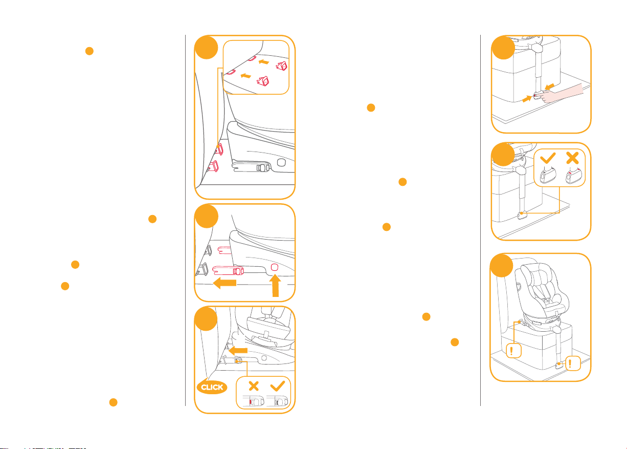
41!After attaching the ISOFIX, pull the
load leg downward to floor. When
the load leg indicator shows green,
the load leg is installed correctly.
!Squeeze the load leg releasing
button, then adjust the load leg
length. 7
!The load leg has 12 positions.
When the load leg indicator shows
red this means the load leg is in the
wrong position. 8
!Make sure the load leg is in full
contact with the vehicle floor pan.
Red means it is installed
incorrectly. 8
!Check to make sure the base is
securely installed by pulling on
both ISOFIX connectors.
!The ISOFIX connectors must be
attached and locked onto the
ISOFIX anchor points. 9-1
!The load leg must be installed
correctly with green indicator. 9-2
Please refer to rear facing mode and
recline positions mode in the later
sections to use the child restraint.
7
8
9
1
2
! Insert ISOFIX guides to assist with
installation. 4-1
! There are 10 adjustable positions for
ISOFIX. Press the ISOFIX adjuster
button to extend the ISOFIX. 5
! The ISOFIX connectors can be
extended for easier installation.
Press the ISOFIX adjustment
buttons 5-1 then pull the ISOFIX
connectors completely out of the
base 5-2. After successfully
installing the ISOFIX connectors,
press the ISOFIX adjustment
buttons again while pushing the
seat back against the vehicle
backrest.
! Make sure that both ISOFIX
connectors are securely attached to
their ISOFIX anchor points. The
colors of the indicators on both
ISOFIX connectors should be
completely green. 6-1
5
1
2
1
6
2