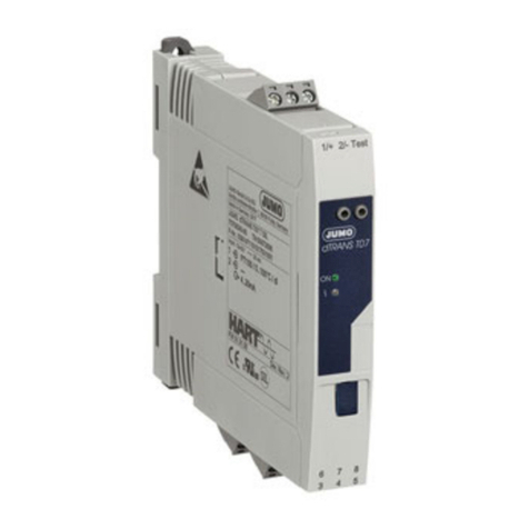
JUMO dTRANS T07 Reference guide

70708000T97Z001K000
V2.00/EN/00681622
JUMO dTRANS T07
Two-channel temperature transmitter
with HART®/Ex/SIL for installation in terminal head,
B form, and for mounting on DIN rails
Brief Instructions


Contents
Contents
1 Important information about this document. . . . . . . . . . . . . . . . . . . . . . . . . . 5
1.1 How this document works and how to use it. . . . . . . . . . . . . . . . . . . . . . . . . . . . . . . . . . . . . . . . 5
1.1.1 How this document works . . . . . . . . . . . . . . . . . . . . . . . . . . . . . . . . . . . . . . . . . . . . . . . . . . . . . . 5
1.1.2 Safety information . . . . . . . . . . . . . . . . . . . . . . . . . . . . . . . . . . . . . . . . . . . . . . . . . . . . . . . . . . . . 5
1.1.3 Functional safety. . . . . . . . . . . . . . . . . . . . . . . . . . . . . . . . . . . . . . . . . . . . . . . . . . . . . . . . . . . . . 5
1.2 Symbols . . . . . . . . . . . . . . . . . . . . . . . . . . . . . . . . . . . . . . . . . . . . . . . . . . . . . . . . . . . . . . . . . . . 5
1.2.1 Warning symbols. . . . . . . . . . . . . . . . . . . . . . . . . . . . . . . . . . . . . . . . . . . . . . . . . . . . . . . . . . . . . 5
1.2.2 Note symbols . . . . . . . . . . . . . . . . . . . . . . . . . . . . . . . . . . . . . . . . . . . . . . . . . . . . . . . . . . . . . . . 5
1.3 Other applicable device documentation . . . . . . . . . . . . . . . . . . . . . . . . . . . . . . . . . . . . . . . . . . . 6
1.4 Registered trademarks . . . . . . . . . . . . . . . . . . . . . . . . . . . . . . . . . . . . . . . . . . . . . . . . . . . . . . . . 6
2 Basic safety information. . . . . . . . . . . . . . . . . . . . . . . . . . . . . . . . . . . . . . . . . . 7
2.1 Requirements for personnel . . . . . . . . . . . . . . . . . . . . . . . . . . . . . . . . . . . . . . . . . . . . . . . . . . . . 7
2.2 Intended use . . . . . . . . . . . . . . . . . . . . . . . . . . . . . . . . . . . . . . . . . . . . . . . . . . . . . . . . . . . . . . . . 7
2.3 Operational safety. . . . . . . . . . . . . . . . . . . . . . . . . . . . . . . . . . . . . . . . . . . . . . . . . . . . . . . . . . . . 7
3 Identifying the device version . . . . . . . . . . . . . . . . . . . . . . . . . . . . . . . . . . . . . 8
3.1 Nameplate. . . . . . . . . . . . . . . . . . . . . . . . . . . . . . . . . . . . . . . . . . . . . . . . . . . . . . . . . . . . . . . . . . 8
3.2 Order details . . . . . . . . . . . . . . . . . . . . . . . . . . . . . . . . . . . . . . . . . . . . . . . . . . . . . . . . . . . . . . . 10
3.3 Scope of delivery . . . . . . . . . . . . . . . . . . . . . . . . . . . . . . . . . . . . . . . . . . . . . . . . . . . . . . . . . . . 10
3.4 Accessories. . . . . . . . . . . . . . . . . . . . . . . . . . . . . . . . . . . . . . . . . . . . . . . . . . . . . . . . . . . . . . . . 11
3.5 Certificates and approvals . . . . . . . . . . . . . . . . . . . . . . . . . . . . . . . . . . . . . . . . . . . . . . . . . . . . 11
3.5.1 CE identification marking and declaration of conformity . . . . . . . . . . . . . . . . . . . . . . . . . . . . . . 11
3.5.2 Certification of the HART® protocol . . . . . . . . . . . . . . . . . . . . . . . . . . . . . . . . . . . . . . . . . . . . . 11
3.5.3 Functional safety. . . . . . . . . . . . . . . . . . . . . . . . . . . . . . . . . . . . . . . . . . . . . . . . . . . . . . . . . . . . 11
4 Mounting . . . . . . . . . . . . . . . . . . . . . . . . . . . . . . . . . . . . . . . . . . . . . . . . . . . . . 12
4.1 Acceptance of goods, storage, and transport . . . . . . . . . . . . . . . . . . . . . . . . . . . . . . . . . . . . . . 12
4.1.1 Goods acceptance . . . . . . . . . . . . . . . . . . . . . . . . . . . . . . . . . . . . . . . . . . . . . . . . . . . . . . . . . . 12
4.1.2 Transport and storage. . . . . . . . . . . . . . . . . . . . . . . . . . . . . . . . . . . . . . . . . . . . . . . . . . . . . . . . 12
4.2 Conditions for installation . . . . . . . . . . . . . . . . . . . . . . . . . . . . . . . . . . . . . . . . . . . . . . . . . . . . . 12
4.2.1 Dimensions . . . . . . . . . . . . . . . . . . . . . . . . . . . . . . . . . . . . . . . . . . . . . . . . . . . . . . . . . . . . . . . . 12
4.2.2 Mounting site. . . . . . . . . . . . . . . . . . . . . . . . . . . . . . . . . . . . . . . . . . . . . . . . . . . . . . . . . . . . . . . 13
4.2.3 Important environmental influences . . . . . . . . . . . . . . . . . . . . . . . . . . . . . . . . . . . . . . . . . . . . . 13
4.3 Mounting . . . . . . . . . . . . . . . . . . . . . . . . . . . . . . . . . . . . . . . . . . . . . . . . . . . . . . . . . . . . . . . . . . 13
4.3.1 Mounting the head transmitter . . . . . . . . . . . . . . . . . . . . . . . . . . . . . . . . . . . . . . . . . . . . . . . . . 14
4.3.2 DIN rail device installation. . . . . . . . . . . . . . . . . . . . . . . . . . . . . . . . . . . . . . . . . . . . . . . . . . . . . 17
4.4 Mounting checklist . . . . . . . . . . . . . . . . . . . . . . . . . . . . . . . . . . . . . . . . . . . . . . . . . . . . . . . . . . 17

Contents
5 Electrical connection . . . . . . . . . . . . . . . . . . . . . . . . . . . . . . . . . . . . . . . . . . . 18
5.1 Installation notes . . . . . . . . . . . . . . . . . . . . . . . . . . . . . . . . . . . . . . . . . . . . . . . . . . . . . . . . . . . . 18
5.2 Terminal assignment for the head transmitter. . . . . . . . . . . . . . . . . . . . . . . . . . . . . . . . . . . . . . 19
5.3 Terminal assignment for DIN rail devices . . . . . . . . . . . . . . . . . . . . . . . . . . . . . . . . . . . . . . . . . 21
5.4 Connecting sensor lines . . . . . . . . . . . . . . . . . . . . . . . . . . . . . . . . . . . . . . . . . . . . . . . . . . . . . . 23
5.5 Connecting the voltage supply and signal cable. . . . . . . . . . . . . . . . . . . . . . . . . . . . . . . . . . . . 24
5.6 Shielding and earthing . . . . . . . . . . . . . . . . . . . . . . . . . . . . . . . . . . . . . . . . . . . . . . . . . . . . . . . 25
5.7 Connection checklist . . . . . . . . . . . . . . . . . . . . . . . . . . . . . . . . . . . . . . . . . . . . . . . . . . . . . . . . . 25
6 Operation . . . . . . . . . . . . . . . . . . . . . . . . . . . . . . . . . . . . . . . . . . . . . . . . . . . . . 27
6.1 Measured value display and operating elements . . . . . . . . . . . . . . . . . . . . . . . . . . . . . . . . . . . 27
6.1.1 Head transmitter with optional BD7 plug-in display . . . . . . . . . . . . . . . . . . . . . . . . . . . . . . . . . 27
6.1.2 Display elements. . . . . . . . . . . . . . . . . . . . . . . . . . . . . . . . . . . . . . . . . . . . . . . . . . . . . . . . . . . . 27
6.1.3 Operating on-site . . . . . . . . . . . . . . . . . . . . . . . . . . . . . . . . . . . . . . . . . . . . . . . . . . . . . . . . . . . 28
6.2 Transmitter configuration and HART® protocol . . . . . . . . . . . . . . . . . . . . . . . . . . . . . . . . . . . . 29
7 Startup . . . . . . . . . . . . . . . . . . . . . . . . . . . . . . . . . . . . . . . . . . . . . . . . . . . . . . . 30
7.1 Installation checklist . . . . . . . . . . . . . . . . . . . . . . . . . . . . . . . . . . . . . . . . . . . . . . . . . . . . . . . . . 30
7.2 Switching on the transmitter . . . . . . . . . . . . . . . . . . . . . . . . . . . . . . . . . . . . . . . . . . . . . . . . . . . 30
7.3 Enabling parameterization . . . . . . . . . . . . . . . . . . . . . . . . . . . . . . . . . . . . . . . . . . . . . . . . . . . . 30

5
1 Important information about this document
1.1 How this document works and how to use it
1.1.1 How this document works
These instructions contain information that is required in the various phases of the device's lifecycle:
from product identification, product acceptance and storage to mounting, connection, basic operation,
and startup, through to troubleshooting, maintenance and disposal.
1.1.2 Safety information
When using the device in potentially explosive areas, you must adhere to any relevant national stan-
dards. A separate Ex safety manual has been created for measuring systems that are used in potentially
explosive areas; this safety manual forms an integral component of this operating manual. The installa-
tion regulations, connection values and safety information contained in this manual must also be ob-
served at all times. Always make sure you are using the Ex safety manual that corresponds to your Ex-
approved device. The number for the corresponding Ex safety manual can be found on the nameplate.
You can only use an Ex safety manual when both numbers (on the Ex safety manual and on the name-
plate) match completely.
1.1.3 Functional safety
NOTE!
Observe the SIL safety manual when using approved devices in safety-related systems according to
IEC 61508.
1.2 Symbols
1.2.1 Warning symbols
CAUTION!
This symbol in connection with the signal word indicates that material damage or data loss will occur
if the respective precautionary measures are not taken.
CAUTION!
This symbol indicates that components could be destroyed by electrostatic discharge (ESD = Electro
Static Discharge) if the respective cautionary measures are not taken.
Only use the ESD packages intended for this purpose to return device inserts, assembly groups, or as-
sembly components.
1.2.2 Note symbols
NOTE!
This symbol refers to important information about the product, its handling, or additional benefits.
REFERENCE!
This symbol refers to additional information in other sections, chapters, or other manuals.

1 Important information about this document
6
1.3 Other applicable device documentation
NOTE!
The documents listed are available:
At www.jumo.net, under "Documentation" on the product page for the dTRANS T07.
1.4 Registered trademarks
Document Purpose and content of the document
Data sheet
JUMO dTRANS T07
Planning aid for the device
The document provides all technical data related to the device
and an overview of all accessories that can be ordered for the de-
vice.
Operating manual
JUMO dTRANS T07
Detailed manual
The manual provides all information, from the receipt of goods, to
the description of parameters and troubleshooting.
Safety Manual SIL
JUMO dTRANS T07
This manual for functional safety according to IEC 61508:2010
describes deviating requirements for device installation, startup,
and operation of the safety function.
Safety Manual Ex
JUMO dTRANS T07
Safety information and technical data for electrical equipment for
potentially explosive areas according to Directive 2014/34/EU
(ATEX).
HART® Trademark registered to the FieldComm Group™

7
2 Basic safety information
2 Basic safety informati on
2.1 Requirements for personnel
Staff involved in installation, startup, diagnosis, and maintenance must meet the following criteria:
• Qualified personnel: Hold qualifications for their function and area of work
• Have been authorized by the system operator
• Are familiar with local regulations
• Prior to starting work: Have read and understood the instructions in this manual and additional doc-
umentation, as well as any certificates (depending on the application)
• Follow instructions and note underlying conditions
Operating staff must meet the following criteria:
• Have been authorized by the system operator and have received instructions in line with the require-
ments of the task at hand
• Follow the instructions in this manual
2.2 Intended use
The dTRANS T07 series is a range of universal and configurable transmitters with either one or two sen-
sor inputs for RTD temperature probes (RTD), thermocouples (TC), potentiometers, and voltage sen-
sors.
The devices are available in two versions: for installation in a B-form terminal head according to DIN EN
50446 or for DIN-rail mounting according to IEC 60715 (TH35). Using a mounting element available as
an accessory, the head transmitter can also be mounted to DIN rail.
The manufacturer is not liable for any damage resulting from improper use or failure to observe the in-
tended use.
2.3 Operational safety
NOTE!
The device must be in good technical working order and safe for operation during use.
The operator is responsible for operating the device without disruptions.
Areas that require approval
To prevent any risk to persons or the plant when the device is used in areas subject to approval require-
ments (e.g., explosion protection or safety-related systems):
• Use the technical data on the nameplate to check whether the ordered device can be used for its
intended purpose in the approval-relevant area; the nameplate is located on the side of the transmit-
ter housing
• Observe any specifications in separate documentation that forms an integral part of these instruc-
tions
Fault safety
The measurement device meets all general safety requirements according to EN 61010-1, EMC require-
ments according to the IEC/EN 61326 series, and NAMUR recommendations NE 21 and NE 89.
NOTE!
Only an SELV voltage is admissible for external voltage supply. The device must be equipped with an
electrical circuit that meets the requirements of EN 61010-1 with regard to "Limited-energy circuits".

8
3 Identifying the device version
3 Ident ifying the devic e version
3.1 Nameplate
Nameplate on the head transmitter
(1) Device type
Compare the specifications on the nameplate with your order documents. The supplied device version
can be identified using the order code in 10.
Example: Type 707086/8-06 (dTRANS T07 B Ex SIL – Two-wire transmitter with Ex and SIL approval
for installation in terminal head, form B)
(2) Part no. (TN)
The part no. uniquely identifies an article in the catalog. It is important for communication between the
customer and the sales department.
(3) Fabrication number (F-Nr)
The date of manufacture (year/calendar week) and the hardware version number are some of the as-
pects specified in the fabrication number.
Example: 0093177001017101002
Here, we are looking at the 12th to the 15th digit (from the left).
The device was produced in the 10th week of 2017.
(4) Inputs and output
Example: Input 1 configured for Pt100 in a 3-wire circuit for a temperature range of 0 to 100 °C, input 2
is not configured, output 4 to 20 mA.
(5) Device revision and firmware version
Example: Device revision 2, firmware version 01.01.10.
(6) Approvals and certificates
Example: Device is SIL and UL-approved and CE-compliant.
(7) Voltage supply and admissible ambient temperature in SIL mode
Example: Voltage range DC 11 to 30 V, current consumption 23 mA, admissible ambient temperature in
SIL mode -40 to +70 °C.
(8) Ex-approvals
Identification marking for approval in potentially explosive areas according to the ATEX Directive and
designation for the corresponding Ex safety manual (installation on ...)
XXXxxATEXxxxx IECEx XXX xx xxxx
II1G Ex ia IIC T6...T4 Ga Ta= -40...+55/70/85°C
II2G Ex ia IIC T6...T4 Gb Ta= -40...+58/75/85°C
Install per 70708000T99Z00XK000
11-30V / 23mA
Ta= -40...+70°C (SIL)
Made in Germany 2017
Dev. Rev.: 2
FW 01.01.10
JUMO dTRANS T07 B Ex SIL
707086/8-06 TN:00672698
1
2
Pt100 / 0..100°C / 3W
---
4..20mA
JUMO GmbH & Co.KG
Moritz-Juchheim-Straße 1, 36039 Fulda, Germany
F-Nr.:
0093177001017101002
(1)
(3)(4)(5)(6)(7)
(2)
(8)

9
3 Identifying the device version
Nameplate on DIN rail devices
(1) Device type
Compare the specifications on the nameplate with your order documents. The supplied device version
can be identified using the order code in 10.
Example: Type 707088/8-06 (dTRANS T07 T Ex SIL – 2-wire transmitter with Ex and SIL approval for
mounting on DIN rails)
(2) Part no. (TN)
The part no. uniquely identifies an article in the catalog. It is important for communication between the
customer and the sales department.
(3) Voltage supply and admissible ambient temperature in SIL mode
Example: Voltage range DC 12 to 30 V, current consumption 23 mA, admissible ambient temperature in
SIL mode -40 to +70 °C.
(4) Ex-approvals
Identification marking for approval in potentially explosive areas according to the ATEX Directive and
designation for the corresponding Ex safety manual (installation on ...)
(5) Approvals and certificates
Example: Device is SIL and UL-approved and CE-compliant.
(6) Firmware version and device revision
Example: Firmware version 01.01.08, device revision 2.
(7) Inputs and output
Example: Input 1 configured for Pt100 in a 3-wire circuit for a temperature range of 0 to 100 °C, input 2
is not configured, output 4 to 20 mA.
(8) Fabrication number (F-Nr)
The date of manufacture (year/calendar week) and the hardware version number are some of the as-
pects specified in the fabrication number.
Example: 0091471101017031001
Here, we are looking at the 12th to the 15th digit (from the left).
The device was produced in the 3rd week of 2017.
Input: 12-30V 23 mA
0044
Made in Germany 2017
FW: . . Dev. Rev.:01 01 08 2
JUMO dTRANS T07 Ex SIL
707088/8-06 TN:00672700
F-Nr.: 0091471101017031001
JUMO GmbH & Co.KG
Moritz-Juchheim-Straße 1, 36039 Fulda, Germany
1
2
Pt100 / 0..100°C / 3W
---
4..20mA
XXXxxATEXxxxx IECEx XXX xx.xxxx
II2(1)G Ex ib[ia Ga] IIC T6...T4 Gb
Ta= -40...+41/56/85°C T6/T5/T4
Install per 70708000T99Z00XK000
(1) (2)
(8) (3)
(4)
(5)
(7)
(6)
Ta= -40...+70°C (SIL)

3 Identifying the device version
10
3.2 Order details
3.3 Scope of delivery
(1) Basic type
707080 dTRANS T07 B – Two-wire transmitter for installation in terminal
head, form B
707081 dTRANS T07 B SIL – Two-wire transmitter with SIL approval for in-
stallation in terminal head, form B
707082 dTRANS T07 T – Two-wire transmitter for mounting on DIN rail
707083 dTRANS T07 T SIL – Two-wire transmitter with SIL approval for
mounting on DIN rail
707085 dTRANS T07 B Ex – Two-wire transmitter with Ex approval for in-
stallation in terminal head, form B
707086 dTRANS T07 B Ex SIL – Two-wire transmitter with Ex and SIL ap-
proval for installation in terminal head, form B
707087 dTRANS T07 T Ex – Two-wire transmitter with Ex approval for
mounting on DIN rail
707088 dTRANS T07 T Ex SIL – Two-wire transmitter with Ex and SIL ap-
proval for mounting on DIN rail
(2) Configuration
XXXXXXXX 8 Default settings (0to100°C, Pt100 three-wire circuit, 4to20mA)
(3) Electrical connection type
XXXXXXXX 06 Screw terminals
(1) (2) (3)
Order code /-
Order example 707080 / 8 - 06
Type
707080 707081 707082 707083 707085 707086 707087 707088
Transmitter in the version ordered XXXXXXXX
Operating manual -- -- -- -- -- -- -- --
SIL safety manual -- X -- X -- X -- X
Ex safety manual -- -- -- -- X X X X
Mounting materials (for mounting in the
terminal head)
XX----XX----
Quick start guide X X X X X X X X

11
3 Identifying the device version
3.4 Accessories
3.5 Certificates and approvals
The device left the factory in perfectly safe working order. The device meets the requirements of the stan-
dard EN 61010-1 "Safety Requirements for Electrical Equipment for Measurement, Control, and Labo-
ratory Use" as well as the EMC requirements under the IEC/EN 61326 series.
3.5.1 CE identification marking and declaration of conformity
The device meets the legal requirements of EU/EEU Directives. The manufacturer confirms compliance
with the relevant directives with the use of the CE mark.
3.5.2 Certification of the HART® protocol
The temperature transmitter is registered by the FieldComm Group™. The device meets the require-
ments of HART® Communication Protocol Specifications, Revision 7.
3.5.3 Functional safety
Options for both device versions (head transmitter/DIN rail device) are available for use in safety-related
systems according to IEC 61508.
• SIL 2: Hardware version
• SIL 3: Software version
Designation Part no.
BD7 plug-in display for dTRANS T07 BD7 00672701
AB7 terminal head for dTRANS T07 B 00672702
FG7 field housing with display window for dTRANS T07 B 00672705
MW7 wall mounting set for field housing 00672707
MR7 tube mounting set for field housing 00672708
HART modem USB 00443447
Mounting element for mounting type 707080 B on DIN rail TH 35 00352463
End holder (screwable) for DIN rail TH 35 00528648
Ex-i repeater power supply/input isolating amplifier type 707530/38 00577948

12
4 Mounting
4 Mounting
4.1 Acceptance of goods, storage, and transport
4.1.1 Goods acceptance
• Is the packaging and its contents free from damage?
• Is the delivered product complete? Compare the scope of delivery with your order details.
4.1.2 Transport and storage
• The device must be packaged so that it is protected against impacts during storage (and transport).
The original packaging offers optimal protection.
• Admissible storage temperature:
Head transmitter -50 to +100 °C
DIN rail device -40 to +100 °C
4.2 Conditions for installation
4.2.1 Dimensions
Head transmitter
DIN rail device
Ø 5
C
B
Ø7
Ø 44
33
A
24.1
ASpring deflection mounting screws ≥ 5 mm (not with US-M4 mounting screws)
BMounting elements for plug-on display BD7
Cinternal service interface (not intended for use)
17.5 114.9
100
112.8
dTRANS T07

13
4 Mounting
4.2.2 Mounting site
• Head transmitter:
In terminal head, form B, according to DIN EN 50445 directly mounted to a measuring insert with a
cable passage (central hole 7 mm), in field housing, offset from process.
• DIN rail transmitter:
Designed to be mounted on DIN rails (IEC 60715 TH35)
NOTE!
Using the accessory "Mounting element for mounting type 707080 B onto DIN rails TH 35", the head
transmitter can also be mounted on DIN rails according to IEC 60715.
4.2.3 Important environmental influences
• Ambient temperature: -40 to +85 °C, in SIL mode: -40 to +70 °C.
• Head transmitter according to climate class C1, DIN rail device according to B2 according to EN
60654-1
• Condensation according to IEC 60068-2-33 admissible for head transmitter, not admissible for DIN
rail device
• Maximum relative humidity: 95 % according to IEC 60068-2-30
• Head transmitter protection type: IP00. Depending on the terminal head used when installed. When
installed in field housing FG7: IP66/67 (NEMA Type 4x encl.)
• DIN rail device protection type: IP20
NOTE!
For application in potentially explosive areas, the limit values for the certificates and approvals (see Ex
safety manual of dTRANS T07) must be met.
4.3 Mounting
A cross-head screwdriver is required when mounting the head transmitter.
NOTE!
Do not screw the mounting screws too tight otherwise the head transmitter could be damaged, maximum
torque = 1 Nm.

4 Mounting
14
4.3.1 Mounting the head transmitter
Mounting a terminal head, form B, according to DIN 43729
Process:
1. Open the lid to the terminal head (8).
2. Guide the connecting wires (4) for the measuring insert (3) through the central hole in the head trans-
mitter (5).
3. Place the mounting springs (6) onto the mounting screws (7).
4. Guide the mounting screws (7) through the side holes in the head transmitter and the measuring in-
sert (3). Then secure both the mounting screws with retaining rings (2).
5. Then tighten the head transmitter (5) with the measuring insert (3) in the terminal head.
6. After completing the wiring process, see page 18, close the lid to the terminal head (8) tightly.
(1) Terminal head (6) Mounting springs
(2) Retaining rings (7) Mounting screws
(3) Measuring insert (8) Lid to terminal head
(4) Connection wires (9) Cable passage
(5) Head transmitter
()1
()2
()3
()4
()5
()6
()7
()9
()8

15
4 Mounting
Mounting in field housing for wall mounting (A) or pipe mounting (B)
Process:
1. Open the lid (1) to the field housing (4).
2. Guide the mounting screws (2) through the side holes in the head transmitter (3).
3. Screw the head transmitter tightly onto the field housing.
4. After completing the wiring process, see page 18, close the lid to the field housing (1).
(1) Lid to field housing (3) Head transmitter
(2) Mounting screws with springs (4) Field housing
()1
120
120
(2) (3) (4)
21
140
Ø 6,5
(A)
(B)

4 Mounting
16
Mounting on DIN rails according to IEC 60715
Process:
1. Press the mounting element (4) onto the DIN rail (5) until it engages.
2. Place the mounting screws onto the mounting screws (1) and guide these through the side holes in
the head transmitter (2). Then secure both the mounting screws with retaining rings (3).
3. Tightly screw the head transmitter (2) onto the mounting element for the DIN rail (4).
(1) Mounting screws with springs (4) Mounting element for DIN rail
(2) Head transmitter (5) DIN rail
(3) Retaining rings
()1 (2) (3) (4) (5)

17
4 Mounting
4.3.2 DIN rail device installation
NOTE!
Mount the device vertically and make sure it is pointing in the right direction (sensor connection at the
bottom/voltage supply at the top)!
If the installation position is wrong, the measurement will not meet the maximum measuring accuracy
when connecting a thermocouple and when using the internal cold junction.
1. Slide the top DIN rail clip (1) up and the bottom clip (2) down until they engage.
2. Place the device (3) onto the DIN rail (4) from the front.
3. Slide the two DIN rail clips toward the DIN rail until they engage.
4.4 Mounting checklist
Perform the following checks after mounting the device:
(1) Top DIN rail clip (3) DIN rail device
(2) Bottom DIN rail clip (4) DIN rail
(1)
(3)
(4)
(2)
State and specifications of the device Important information
Does the device show any signs of damage (visual
check)?
-
Do the environmental influences meet the device's spec-
ifications (e.g., ambient temperature, measuring range)?
Page 13

18
5 Electrical connection
5.1 Installation notes
A cross-head screwdriver is required when wiring the head transmitter with screw terminals. Use a cross-
head screwdriver to wire DIN rail devices.
CAUTION!
Destruction of electronic components or the entire electronics system
Do not install or wire the device under operating voltage.
Do not connect a third-party connection to the connector for the head transmitter's plug-in display.
CAUTION!
Failure to adhere to approval requirements for devices with Ex approval
When connecting devices with Ex approval, observe the notes and connection diagrams in the Ex
safety manual (additional documentation) for this device.
NOTE!
Do not screw the mounting screws too tight otherwise the transmitter could be damaged. Use a suitable
screwdriver.
• Maximum torque for mounting screws = 1 Nm, screwdriver: Pozidriv PZ2
• Maximum torque for screw terminals = 0.35 Nm, screwdriver: Pozidriv PZ1
Always complete the following steps when wiring an installed head transmitter:
1. Open the cable fitting and case lid on the terminal head or field housing.
2. Guide the wires through the opening in the cable fitting.
3. Connect the wires according to the connection diagram on page 19.
4. Tighten the cable fitting again and then close the case lid.
To prevent connection errors, always read the notes in the connection checklist prior to startup.

19
5 Electrical connection
5.2 Terminal assignment for the head transmitter
Connection for Explanations Terminals
Voltage supply
DC 11 to 42 V (standard)
DC 11 to 32 V (SIL)
Rbmax. = (Ubmax.–11V)÷0.023A
Rb= load resistance
Ub= voltage supply
Current output
4to20mA
HART communication Burden ≥ 250 Ω required in the signal circuit
Analog input (sensor input) 1
RTD temperature probe ▪ Sensor current ≤ 0.3 mA
▪ Compensation for the line resistance is possible
(0 to 30 Ω)
2-wire circuit
RTD temperature probe ▪ Sensor current ≤ 0.3 mA
▪ Sensor line resistance max. 50 Ω per line
3-wire circuit
RTD temperature probe ▪ Sensor current ≤ 0.3 mA
▪ Sensor line resistance max. 50 Ω per line
4-wire circuit
Resistance/potentiometer ▪ Sensor current ≤ 0.3 mA
▪ Compensation for the line resistance is possible
(0 to 30 Ω)
2-wire circuit
Resistance/potentiometer ▪ Sensor current ≤ 0.3 mA
▪ Sensor line resistance max. 50 Ω per line
3-wire circuit
Resistance/potentiometer ▪ Sensor current ≤ 0.3 mA
▪ Sensor line resistance max. 50 Ω per line
4-wire circuit
Thermocouple
Voltage sensor
2
1
+–
456
3
J
7
456
3
J
7
456
3
J
7
456
37
456
37
456
37
456
37
+
456
37
+

5 Electrical connection
20
CAUTION!
Electrostatic discharge!
Failure to observe this information could lead to parts of the electronics system being destroyed or mal-
functioning.
Protect the terminals against electrostatic discharge.
Analog input (sensor input) 2
RTD temperature probe ▪ Sensor current ≤ 0.3 mA
▪ Compensation for the line resistance is possible
(0 to 30 Ω)
2-wire circuit
RTD temperature probe ▪ Sensor current ≤ 0.3 mA
▪ Sensor line resistance max. 50 Ω per line
3-wire circuit
Resistance/potentiometer ▪ Sensor current ≤ 0.3 mA
▪ Compensation for the line resistance is possible
(0 to 30 Ω)
2-wire circuit
Resistance/potentiometer ▪ Sensor current ≤ 0.3 mA
▪ Sensor line resistance max. 50 Ω per line
3-wire circuit
Thermocouple
Voltage sensor
Connection for Explanations Terminals
456
3
J
7
456
3
J
7
456
37
456
37
456
37
+
456
37
+
Other manuals for dTRANS T07
1
Table of contents
Other JUMO Transmitter manuals

JUMO
JUMO 907021/30 User manual

JUMO
JUMO CTI-500 User manual

JUMO
JUMO 4AP-30 User manual

JUMO
JUMO JUMO dTRANS p20 DELTA User manual

JUMO
JUMO TAROS S46 H User manual

JUMO
JUMO dTRANS T06 Ex User manual

JUMO
JUMO 404304 Series User manual

JUMO
JUMO DELOS SI User manual

JUMO
JUMO CTI-500 User manual

JUMO
JUMO JUMO dTRANS p20 DELTA User manual

JUMO
JUMO dTRANS p02 User manual

JUMO
JUMO TAROS S47 P User manual

JUMO
JUMO dTRANS T03 J User manual

JUMO
JUMO ecoTRANS pH 03 User manual

JUMO
JUMO AQUIS 500 CR User manual

JUMO
JUMO B 90.7027.1 User manual

JUMO
JUMO dTRANS O2 01 User manual

JUMO
JUMO dTRANS T09 DS User manual

JUMO
JUMO dTRANS p02 DELTA User manual

JUMO
JUMO SIRAS P21 DP User manual