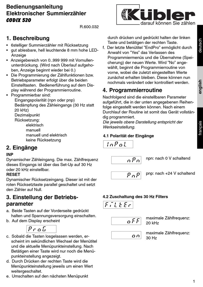
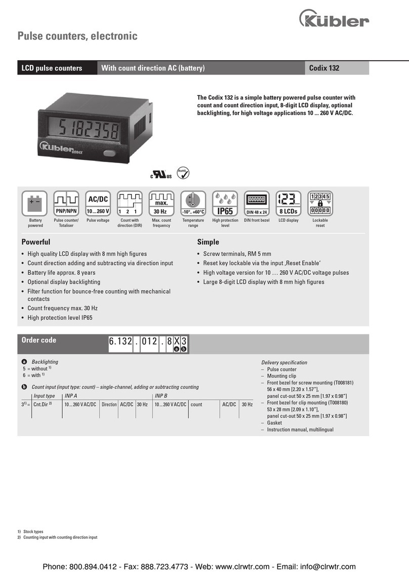
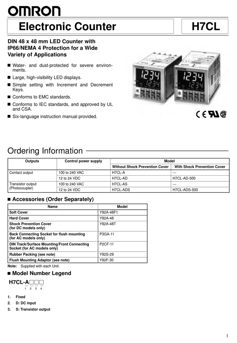
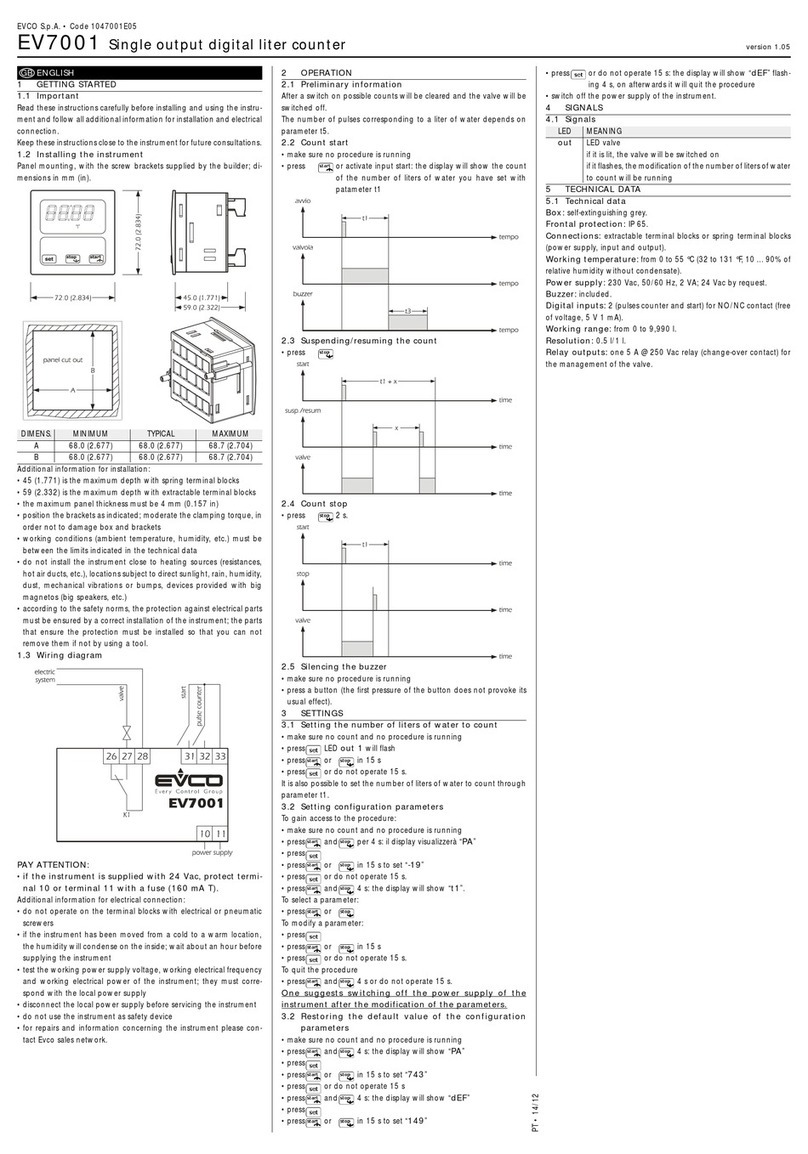
Kübler CODIX 52T User manual

1
españolitalianofrançaisenglishdeutsch
Bedienungsanleitung
Elektronische Anzeigezähler
CODIX 52T
1.1 Sicherheits- und Warnhinweise
Benutzen Sie diese Anzeige nur
– bestimmungsgemäß
– in technisch einwandfreiem
Zustand
– unter Beachtung der Bedien-
ungsanleitung und den allgemei-
nen Sicherheitsbestimmungen.
1.2 Allgemeine Sicherheits- und Warnhinweise
1. Vor Durchführung von Installations- oder War-
tungsarbeiten stellen Sie bitte sicher, dass die
Digitalanzeige von der Versorgungs-
spannung getrennt ist.
2. Setzen Sie die Digitalanzeige nur bestim-
mungsgemäß ein: In technisch einwandfreiem
Zustand. Unter Beachtung der Bedienungsan-
leitung und den allgemeinen Sicherheitsbe-
stimmungen.
3. Beachten Sie länder- und anwendungsspezifi-
sche Bestimmungen
4. Die Digitalanzeige ist nicht geeingnet für den
explosionsgeschützten Bereich und den in-
satzbereichen, die in N 61010 Teil 1 ausge-
schlossen sind.
5. Die Digitalanzeige darf nur im ordnungsgemäß
eingebautem Zustand entsprechend dem
Kapitel “Technische Daten” betrieben werden.
1.3 Bestimmungsgemäßer Gebrauch
Die Digitalanzeige darf nur als inbaugerät ein-
gesetzt werden. Der insatzbereich dieser Anzei-
ge liegt in industriellen Prozessen und Steuerun-
gen. In den Bereichen von Fertigungsstraßen der
Metall-, Holz-, Kunststoff-, Papier-, Glas- und
Textilindustrie u.ä.
Überspannungen an den Schraubklemmen der
Digitalanzeige müssen auf den Wert der Über-
spannungskategorie II begrenzt sein. Wird die
Digitalanzeige zur Überwachung von Maschinen
oder Ablaufprozessen eingesetzt, bei denen
infolge eines Ausfalls oder einer Fehlbedienung
der Digitalanzeige eine Beschädigung der
Maschine oder ein Unfall des Bedienungsper-
sonals möglich ist, dann müssen Sie entspre-
chende Sicherheitsvorkehrungen treffen.
1.4 Beschreibung
Die Ausführung CODIX 52T ist ein Anzeigezäh-
ler mit 2 Summierbereichen.
2. Einstellung der Be triebs pa ra me ter
a. Beide Tasten auf der Vor der sei te gedrückt
hal ten und Span nungs ver sor gung ein schal ten,
oder bei eingeschalteter Spannungsver-sor-
gung beide Tasten gleichzeitig 5 s drücken
b. Auf dem Display erscheint
c. Sobald die Tasten los ge las sen werden,
er scheint auf dem Display
c1. durch gedrückt halten der linken Taste und
betätigen der rechten Taste wird der Pro-
grammiervorgang abgebrochen.
c2. durch Drücken der rechten Taste wird auf
umgeschaltet.
d. Umschalten in den ersten Parameter durch
gedrückt halten der linken Taste und betätigen
der rechten Taste
e. Sobald die Tasten losgelassen werden,
erscheint in sekündlichen Wechsel der Menüti-
tel und die aktuelle Menüpunkt-
einstellung. Nach Betätigen einer Taste wird
nur noch die Menüpunkteinstellung angezeigt.
f. Durch Drücken der rechten Taste wird die
Me nü punkt ein stel lung jeweils um einen Wert
wei ter ge schal tet.
Wenn Zahlenwerte ein ge ge ben werden sollen
(z.B. bei der Fak tor ein stel lung), wird mit der lin-
ken Taste zunächst die De ka de angewählt und
dann mit der rech ten der Wert ein ge stellt.
g. Umschalten auf den näch sten Menüpunkt
durch ge drückt halten der linken Taste und
betätigen der rechten Taste.
!

2
h. Der jeweils letzte Menütitel ” ndPro” ermög-
licht durch An wahl von ”Y S” das Ver las sen
des Programmiermenüs und die Über nah me
(Spei che rung) der neuen Werte.
Wird ”no” an ge wählt, be ginnt die Program-
mierroutine von vorne, wobei die zuletzt ein -
ge stell ten Werte zunächst er hal ten blei ben.
Diese können nun nochmals
verändert oder kon trol liert werden.
Elektronischer Anzeigezähler mit
2 Summierbereichen
1. Beschreibung
• 6-stelliger Anzeigezähler mit Reset-Funktion
• L D-Anzeige, 8 mm hoch, rot
• Anzeigebereich von 0 ... 999 999
• Vor nul len un ter drüc kung
• Programmierung über zwei frontseitige Tasten
• Bedienerführung auf dem Display während der
Programmierung
2. Eingänge
INP A
Dynamischer Zähleingang Zähler 1 und Zähler 2.
ESET
Dynamischer R S T- ingang. Dieser ist mit der
roten R S T-Taste parallel geschaltet und setzt
den Zähler auf Null. Für Zähler 1 und Zähler 2
getrennt einstellbar
3. Auswahl des angezeigten Wertes
Durch drücken der rechten Taste kann zwischen
der Anzeige des Summierzählers 1 und des
Summierzählers 2 umgeschaltet werden. Durch
einmaliges Betätigen wird für 2 s die aktuelle
Funktion (“totAL1” oder “totAL2”) angezeigt. Wird
innerhalb dieser Zeit die rechte Taste ein zwei-
tes Mal betätigt, so wird zur nächsten Funktion
gewechselt und zur Bestätigung (“totAL1” oder
“totAL2”) für 2 s angezeigt. Danach wird der
Wert der ausgewählten Funktion angezeigt.
4. Programmierroutine
Nachfolgend sind die einstellbaren Parameter
des Gerätes aufgeführt, die in der unten ange-
gebenen Reihenfolge eingestellt werden kön-
nen. Nach einem Durchlauf der Routine ist das
Gerät voll stän dig programmiert.
Die zuerst angegebenen Werte entsprechen
der Werkseinstellung
- Technische Änderungen vorbehalten -
4.1 Polarität der Eingänge
npn: nach 0 V schal tend
pnp: nach +UBschaltend
4.2 Zuschaltung des 30 Hz Filters (INP A)
Der Filter bedämpft den in-
gang*
30 Hz-Filter aus (fmax)
30 Hz-Filter ein
Faktor von 00.0001 bis 99.9999
einstellbar. Dezimalpunkt fest
auf 4 Nachkommastellen einge-
stellt. ine instellung von “0”
wird nicht akzeptiert.
4.3 Multiplikationsfaktor (Summierer 1)
Faktor von 00.0001 bis 99.9999
einstellbar. Dezimalpunkt fest
auf 4 Nachkommastellen einge-
stellt. ine instellung von “0”
wird nicht akzeptiert.
4.4 Divisionsfaktor (Summierer 1)
Der Dezimalpunkt legt Dar stel -
lung des Zäh ler stan des fest. r
hat keinen influß auf die Zäh -
lung.
0 keine De zi mal stel le
0.0 eine De zi mal stel le
0.00 zwei De zi mal stel len
0.000 drei De zi mal stel len
4.5 Dezimalpunkteinstellung (Summierer 1)

3
deutsch
- Technische Änderungen vorbehalten -
4.6 ESET-Mode (Summierer 1)
manuelle Rückstellung über die
rote R S T-Taste und elek tri -
sche Rückstellung über
R S T- ingang
keine Rückstellung mög lich
(rote R S T-Taste und R S T-
ingang gesperrt)
nur elektrische Rück stel lung
über R S T- ingang
nur manuelle Rückstellung über
rote R S T-Taste
* bei Prellimpulsen, z.B. bei Kontakten
Faktor von 00.0001 bis 99.9999
einstellbar. Dezimalpunkt fest
auf 4 Nachkommastellen einge-
stellt. ine instellung von “0”
wird nicht akzeptiert.
4.7 Multiplikationsfaktor (Summierer 2)
Faktor von 00.0001 bis 99.9999
einstellbar. Dezimalpunkt fest
auf 4 Nachkommastellen einge-
stellt. ine instellung von “0”
wird nicht akzeptiert.
4.8 Divisionsfaktor (Summierer 2)
Der Dezimalpunkt legt Dar stel -
lung des Zäh ler stan des fest. r
hat keinen influß auf die Zäh -
lung.
0 keine De zi mal stel le
0.0 eine De zi mal stel le
0.00 zwei De zi mal stel len
0.000 drei De zi mal stel len
4.9 Dezimalpunkteinstellung (Summierer 2)
5.0 ESET-Mode (Summierer 2)
manuelle Rückstellung über die
rote R S T-Taste und elek tri -
sche Rückstellung über
R S T- ingang
keine Rückstellung mög lich
(rote R S T-Taste und R S T-
ingang gesperrt)
nur elektrische Rück stel lung
über R S T- ingang
nur manuelle Rückstellung über
rote R S T-Taste
4.8 Ende der Programmierung
Programmierroutine wird noch
einmal durchlaufen. Bisher ein-
gestellte Werte können über-
prüft und geändert werden.
Programmierroutine wird been-
det und alle
ein ge stell ten Werte werden als
neue Parameter über nom men.
Das Gerät ist an schlie ßend
betriebsbereit.

5. Technische Daten
Spannungsversorgung
DC-Versorgung: 10 ... 30 V DC/max. 55 mA
mit Verpolschutz
Anzeige: 6-stellige rote 7-Segment
L D-Anzeige, 8 mm hoch
Datensicherung: PROM
Polarität der Eingänge:
Programmierbar, npn oder
pnp für alle ingänge
Eingangswiderstand:
ca. 5 k⍀
Zählfrequenzen:
DC-Versorgung: 24 V 12 V 10 ...30 V
ingangspegel: Standard 5 V
typ. Low Pegel: 2,5 V 2,0 V 1,0 V
typ. High Pegel: 22,0 V 10 V 4,0 V
Fmax:* kHz kHz kHz
tot.tot 60 20 8
*bei maximaler Frequenz Rechteckimpulse 1:1
Mindestimpulsdauer des ücksetzeingangs:
5 ms
Schaltpegel der Eingänge:
Standard-Pegel: Low: 0 ... 0,2 x UB[V DC]
High: 0,6 x UB... 30 [V DC]
4 ... 30 V DC Pegel: Low: 0 ... 2 V DC
High: 4 ...30 V DC
Impulsform: beliebig*,
Schmitt-Trigger- ingang
Betriebstemperatur:
-20 ... +65 °C bei 10 ... 26 V DC
-20 ... +55 °C bei >26 ... 30 V DC
Lagertemperatur: –25 ... +70 °C
Höhe bis 2000 m
EMV:
Störabstrahlung N 55 011 Klasse B
Störfestigkeit N 61 000-6-2
Gehäuse: Schalttafelgehäuse:
48 x 24 mm nach DIN
43700, RAL7021,
dunkelgrau
4
Gewicht: ca. 50 g
Schutzart: IP 65 (frontseitig)
einigung: Die Frontseiten der Geräte
dürfen nur mit einem wei-
chen, mit Wasser ange-
feuchteten Tuch gereinigt
werden.
6. Anschlussbelegung
1 10 ... 30 V DC
2 0 V GND
3 INP A
4 –
5 Reset
7. Lieferumfang:
1 Digitalanzeige
1 Spannbügel
1 Frontrahmen für Spannbügelbefestigung,
für inbauquerschnitt 50 x 25 mm
1 Frontrahmen für Schraubbefestigung,
für inbauquerschnitt 50 x 25 mm
1 Dichtung
1 Bedienungsanleitung multilingual
8. Bestellschlüssel:
6.52T.012.3X0
Schaltpegel der ingänge
0 = Standard
A = 4 ... 30 V DC Pegel

9. Abmessungen:
Schalttafelausschnitt:
22,2+0,3 x 45+0,6 mm
inbaurahmen Schalttafelausschnitt:
Senkung Af3, DIN 74
1
5
deutsch
1
0
I
–
5 R


1
english
Operating instructions
Electronic display counter
CODIX 52T
1.1 Safety instructions and warnings
Only use this display
– in a way according to its intended
purpose
– if its technical condition is perfect
– adhering to the operating
instructions and the general
safety instructions.
1.2 General safety instructions
1. Before carrying out any installation or mainte-
nance work, make sure that the power supply
of the digital display is switched off.
2. Only use this digital display in a way according
to its intended purpose: If its technical condi-
tion is perfect. Adhering to the operating
instructions and the general safety instruc-
tions.
3. Adhere to country or user specific regulations.
4. The digital display is not intended for use in
areas with risks of explosion and in the
branches excluded by the standard N 61010
Part 1.
5. The digital display shall only operated if it has
been correctly mounted in a panel, in accor-
dance with the chapter “Main technical fea-
tures”.
1.3 Use according to the intended purpose
The digital display may be used only as a panel-
mounted device. Applications of this product
may be found in industrial processes and con-
trols, in manufacturing lines for the metal, wood,
plastics, paper, glass, textile and other process-
ing industries.
Over-voltages at the terminals of the digital dis-
play must be kept within the limits in Category II
If the digital display is used to monitor machines
or processes in which, in case of a failure of the
device or an error made by the operator, there
might be risks of damaging the machine or caus-
ing accidents to the operators, it is your responsi-
bility to take appropriate safety measures.
1.4 Description
The CODIX 52T is a display counter with 2 total-
ising ranges.
2. Setting of the operating pa ra me ters
a. Press both front side keys keys and switch on
the supply voltage or, if the supply voltage is
already on, press both keys simultaneously
during 5 s.
b. The display shows
c. After releasing the keys, the display shows
c1. Hold the left key pressed and press the right
key to leave the programming operation.
c2. Press the right key to switch to
.
d. Hold the left key pressed and press the right
key to switch to the first parameter.
e. After releasing the keys, the display alter-
nates between the menu title and the current
menu item setting. After pressing any key, only
the menu item setting is displayed.
f. Pressing the right key, the menu item setting
will be switched to the next value.
If figures are to be input (e.g. when setting the
scaling factor), select first the decade using
the left key, and then set the value using the
right key.
g. Hold the left key pressed and press the right
key to switch to the next menu item.
h. The last menu title ” ndPro” allows, when
selecting “Yes”, to exit the programming menu
and to take over (store) the new values.
If “no” is selected, the programming routine is
repeated, the latest values set remaining
active. They can now be checked again or
modified.
!

* where bounce occurs, e.g. with contacts
2
Electronic display counter with
2 totalising ranges
1. Description
• 6-digit dislay counter with Reset function
• Red L D display, character height 8 mm
• Display range 0 ... 999 999
• Leading zeros suppression
• Programming via two setting keys on the front
side
• During programming, the display guides the
user with text prompts
2. Inputs
INP A
Dynamic count input Counter 1 and Counter 2.
ESET
Dynamic R S T input. Linked in parallel to the
red R S T key. Sets the counter to zero. Can be
adjusted individually for Counter 1 and Counter 2.
3. Selection of the displayed value
Pressing the right key allows switching between
the display of totaliser 1 and the display of
totaliser 2. Press the key briefly to display for 2
seconds the current function (“total1” or “total2”).
If, during this period of time, the right key is
pressed a second time, the device switches to
the next function and displays a confirmation
(“total1” or “total2”) for 2 seconds. Then, the
value of the selected function is displayed.
4. Programming routine
The programmable parameters of the device are
described below, in the order in which they can
be set. The device is fully programmed after one
pass of the routine.
The first values stated correspond to the
factory settings
- Subject to change without prior notice -
4.1 Polarity of the inputs
npn: switching for 0 V
pnp: switching for +UB
4.2 Switching on the 30 Hz filter (INP A)
It can be set from 00.0001 up
to 99.9999.
The decimal point is set to 4
decimal places.
„0“ is not accepted!
4.3 Multiplying factor (totaliser 1)
It can be set from 00.0001 up
to 99.9999.
The decimal point is set to 4
decimal places.
„0“ is not accepted!
4.4 Dividing factor (totaliser 1)
The decimal point defines the
way of displaying the count val-
ues. It does not affect counting.
0 no decimal place
0.0 one decimal place
0.00 two decimal places
0.000 three decimal places
4.5 Decimal point (totaliser 1)
4.6 ESET mode (totaliser 1)
manual reset via the red
R S T key and electrical reset
via the R S T input
no reset (red R S T key and
R S T input locked)
only electrical reset via the
R S T input
only manual reset via the red
R S T key
The filter provides input damp-
ing*
30 Hz filter off (fmax)
30 Hzfilter on

5. Technical data
Supply voltage
Power supply: 10 ... 30 V DC/max. 55 mA
with inverse-polarity pro-
tection
Display: 6 digits, red 7 segment
L D display, height 8 mm
Data retention: PROM
Polarity of the inputs:
Programmable, npn or pnp
for all inputs
Input resistance: appr. 5 k⍀
Count frequency:
DC power supply: 24 V 12 V 10 ...30 V
Input level: Standard 5V
typ. low level: 2,5 V 2,0 V 1,0 V
typ. ligh level: 22,0 V 10 V 4,0 V
Fmax:* kHz kHz kHz
tot.tot 60 20 8
* at maximum frequency square wave pulses 1:1
Minimum pulse length for the eset input:
5 ms
Input sensitivity:
Standard sensitivity:
Low: 0 ... 0,2 x UB[V DC]
High: 0,6 x UB... 30 [V DC]
4 ... 30 V DC level: Low: 0 ... 2 V DC
High: 4 ...30 V DC
3
english
- Subject to change without prior notice -
It can be set from 00.0001 up
to 99.9999.
The decimal point is set to 4
decimal places. „0“ is not
accepted!
4.7 Multiplying factor (totaliser 2)
It can be set from 00.0001 up
to 99.9999.
The decimal point is set to 4
decimal places. „0“ is not
accepted!
4.8 Dividing factor (totaliser 2)
The decimal point defines the
way of displaying the count val-
ues. It does not affect counting.
0 no decimal place
0.0 one decimal place
0.00 two decimal places
0.000 three decimal places
4.9 Decimal point (totaliser 2)
5.0 ESET Mode (totaliser 2)
manual reset via the red
R S T key and electrical reset
via the R S T input
no reset (red R S T key and
R S T input locked)
only electrical reset via the
R S T input
only manual reset via the red
R S T key
5.1 End of programming
The programming routine is
repeated once more. The val-
ues set until now can be
checked and modified.
The programming routine wil be
left and all values set will be
stored as new parameters.
Afterwards the device is ready
for operation.

4
Pulse shape: any,
Schmitt-Trigger inputs
Ambient temperature:
-20 ... +65 °C at 10 ... 26 V DC
-20 ... +55 °C at >26 ... 30 V DC
Storage temperature:
–25 ... +70 °C
Altitude: to 2000 m
EMC:
Noise emission N 55 011 Class B
Noise immunity N 61 000-6-2
Housing:
For front panel mounting: 48 x 24 mm
acc. to DIN 43700, RAL7021, dark grey
Weight: appr. 50 g
Protection: IP 65 (front)
Cleaning:
The front of the units is to be cleaned only with
a soft wet (water !) cloth.
6. Terminal assignment
1 10 ... 30 V DC
2 0 V GND
3 INP A
4 –
5 Reset
7. Delivery includes:
1 Digital display
1 Panel mounting clip
1 Bezel for screw mounting, panel cut out
50 x 25 mm
1 Bezel for clip mounting, panel cut out
50 x 25 mm
1 Seal
1 Multilingual operating instructions
8. Ordering code:
6.52T.012.3X0
Input sensitivity
0 = Standard
A = 4 ... 30 V DC level

Panel cut out:
22,2+0,3 x 45+0,6 mm
Front bezel Panel cut out:
Counter sinking Af3, DIN 74
1
5
english
9. Dimensions:


1
français
Notice de mise en service
Compteur à affichage électronique
CODIX 52T
1.1 Instructions de sécurité et
avertissements
N’utiliser ces afficheurs que
– de manière conforme à leur
destination
– s’ils sont techniquement en
parfait état
– en respectant les instructions
d’utilisation et les instructions
générales de sécurité.
1.2 Onstructions générales de sécurité
1. Avant tout travail d’installation ou de mainte-
nance, s’assurer que l’alimentation de l’affi-
cheur digital est coupée.
2. N’utiliser cet afficheur que de manière confor-
me à sa destination: Il doit être techniquement
en parfait état. Respecter les instructions d’utili-
sation et les instructions générales de sécurité.
3. Tenir compte des réglementations spécifiques
au pays et à l’utilisateur.
4. L’afficheur digital ne convient pas pour des
zones présentant des risques d’explosion, ni
dans les domaines d’utilisation exclus par la
norme N 61010 Partie 1.
5. L’afficheur digital ne doit être utilisé que s’il a
été encastré dans les règles de l’art, confor-
mément au chapitre “Caractéristiques tech-
niques générales”.
1.3 Utilisation conforme
L’afficheur digital ne peut être utilisé qu’en tant
qu’appareil encastré. Ce produit trouve son appli-
cation dans les process industriels et les com-
mandes, dans le domaine des chaînes de fabrica-
tion des industries du métal, du bois, des matières
plastiques, du papier, du verre, du textile, etc.
Les surtensions aux bornes de l’afficheur digital
doivent être limitées aux valeurs de la catégorie
de surtension II.
Si l’afficheur digital est mis en oeuvre pour la
surveillance de machines ou de process où, en
cas de panne ou d’une erreur de manipulation
de l’appareil, peuvent apparaître des risques de
dommages à la machine ou d’accidents pour les
opérateurs, il vous appartient de prendre les
mesures de sécurité appropriées.
1.4 Description
Le CODIX 52T est un compteur à affichage avec
2 plages de totalisation.
2. églage des pa ra mè tres de
fonctionnement
a. Presser les deux touches de la face avant et
mettre l’appareil sous tension, ou, l’appareil
étant sous tension, presser les deux touches
pendant 5 s.
b. Sur l’affichage apparaît le message
c. Dès que les touches sont relâchées,
l’affichage indique
c1. Maintenir la touche de gauche pressée, puis
presser la touche de droite, pour interrompre
l’opération de programmation.
c2. Presser la touche de droite pour que
l’affichage indique
.
d. Maintenir la touche de gauche pressée, puis
presser la touche de droite, pour appeler le
premier paramètre.
e. Dès relâchement des touches apparaît, par
périodes d’une seconde, le titre du menu et sa
programmation actuelle. Presser une touche :
l’affichage cesse d’alterner et n’indique plus
que le réglage du point du menu.
f. Une impulsion sur la touche de droite permet
de passer à la valeur suivante du paramètre
en cours de réglage. Pour introduire des
valeurs numériques (p. ex. lors du réglage du
facteur), sélectionner d’abord la décade à l’ai-
de de la touche de gauche, puis régler sa
valeur à l’aide de la touche de droite.
!

2
4. outine de programmation
Les paramètres réglables de l’appareil sont indi-
qués ci-dessous dans l’ordre de leur
apparition sur l’affichage. L’appareil est donc
entièrement programmé après un cycle de
programmation.
Les premières valeurs affichées correspondent
au réglage d’usine
g. Pour passer au paramètre suivant du menu,
maintenir la touche de gauche pressée et
presser la touche de droite.
h. Le dernier paramètre du menu, ” ndPro”,
permet, en sélectionnant ”Yes”, de quitter le
menu de programmation et de prendre en
compte (sauvegarder) les nouvelles valeurs.
Si ”No” est sélectionné, la programmation
recommence depuis le début, en conservant
les dernières valeurs introduites. Il est alors
possible de les vérifier ou de les modifier à
nouveau.
Compteur à affichage électronique
avec 2 plages de totalisation
1. Description
• Compteur à affichage à 6 décades avec fonc-
tion Reset
• Affichage par L D rouges, hauteur 8 mm
• Plage d’affichage de 0 à 999 999
• Suppression des zéros de tête
• Programmation par deux touches sur la face
avant
• Programmation guidée par des messages sur
l’affichage
2. Entrées
INP A
ntrée de comptage dynamique Compteur 1 er
Compteur 2.
ESET
ntrée R S T dynamique couplée en parallèle
avec la touche R S T rouge. Remet le comp-
teur à zéro. Réglable séparément pour le Comp-
teur 1 et le Compteur 2.
3. Sélection de la valeur affichée
Presser la touche de droite pour commuter
entre l’affichage du totalisateur 1 et celui du
totalisateur 2. Une impulsion unique affiche pen-
dant 2 s. la fonction courante (“total1” ou
“total2”). Si la touche de droite est pressée à
nouveau pendant ce laps de temps, l’affichage
passe à la fonction courante, et (“total1” ou
“total2”) s’affiche pendant 2 s. pour confirmation.
nsuite, la valeur de la fonction sélectionnée
s’affiche.
- Sous réserve de modifications techniques -
4.1 Polarité des entrées
npn : commutation à 0 V
pnp : commutation à +UB
4.2 Activation du filtre 30 Hz (INP A)
Le filtre atténue l’entrée*
Filtre 30 Hz désactivé (fmax)
Filtre 30 Hz activé
Facteur réglable de 00.0001 à
99.9999.
Point décimal fixe réglé à 4
décimales.
Le réglage à „0“ n’est pas
accepté.
4.3 Facteur de multiplication (totalisateur 1)
Facteur réglable de 00.0001 à
99.9999.
Point décimal fixe réglé à 4
décimales.
Le réglage à „0“ n’est pas
accepté.
4.4 Facteur de division (totalisateur 1)
Le point décimal détermine la
représentation de la valeur de
comptage. Il n’a aucun effet sur
le comptage.
0 pas de décimale
0.0 une décimale
0.00 deux décimales
0.000 trois décimales
4.5 églage du point décimal (totalisateur 1)

3
français
- Sous réserve de modifications techniques -
4.6 Mode ESET (totalisateur 1)
Remise à zéro manuelle par la
touche R S T rouge et élec-
trique par l’entrée R S T
Pas de remise à zéro (touche
R S T rouge et entrée R S T
désactivées)
Remise à zéro électrique par
l’entrée R S T uniquement
Remise à zéro manuelle par la
touche R S T rouge unique-
ment
* rebonds, par ex. avec des contacts mécaniques
Facteur réglable de 00.0001 à
99.9999.
Point décimal fixe réglé à 4
décimales.
Le réglage à „0“ n’est pas
accepté.
4.7 Facteur de multiplication (totalisateur 2)
Facteur réglable de 00.0001 à
99.9999.
Point décimal fixe réglé à 4
décimales.
Le réglage à „0“ n’est pas
accepté.
4.8 Facteur de division (totalisateur 2)
Le point décimal détermine la
représentation de la valeur de
comptage. Il n’a aucun effet sur
le comptage.
0 pas de décimale
0.0 une décimale
0.00 deux décimales
0.000 trois décimales
4.9 églage du point décimal (totalisateur 2)
5.0 Mode ESET (totalisateur 2)
Remise à zéro manuelle par la
touche R S T rouge et élec-
trique par l’entrée R S T
Pas de remise à zéro (touche
R S T rouge et entrée R S T
désactivées)
Remise à zéro électrique par
l’entrée R S T uniquement
Remise à zéro manuelle par la
touche R S T rouge unique-
ment
5.1 Fin de la programmation
La programmation est exécutée
encore une fois. Les valeurs
introduites peuvent être véri-
fiées et modifiées.
La programmation est
terminée et les valeurs intro-
duites sont prises en compte
comme nouveaux paramètres.
L’appareil est alors prêt à fonc-
tionner.

4
5. Caractéristiques techniques
Tension d’alimentation
Alimentation : 10 ... 30 V CC/max. 55 mA
avec protection contre les
inversions de polarité
Affichage : Rouge, 6 décades
L D à 7 segments,
hauteur 8 mm
Mémorisation des données :
PROM
Polarité des entrées:
Programmable, npn ou pnp
pour toutes les entrées
ésistance d’entrée :
env. 5 k⍀
Fréquences de comptage :
Alimentation CC: 24 V 12 V 10 ...30 V
Niveau: Standard 5 V
typ. low: 2,5 V 2,0 V 1,0 V
typ. ligh: 22,0 V 10 V 4,0 V
Fmax*: kHz kHz kHz
tot.tot 60 20 8
*signaux rectangulaires, rapport impulsion/pause 1:1
Niveau de commutation des entrées :
Niveau standard :
Low: 0 ... 0,2 x UB[V CC]
High: 0,6 x UB... 30 [V CC]
Niveau 4 ... 30 V CC:
Low: 0 ... 2 V CC
High: 4 ...30 V CC
Fome des impulsions :
quelconque*, entrée par
trigger de Schmitt
Température ambiante :
-20 ... +65 °C avec 10 ... 26 V DC
-20 ... +55 °C avec >26 ... 30 V DC
Température de stockage :
–25 ... +70 °C
Altitude: jusqu’à 2000 m
CEM :
mission de parasites N 55 011 Classe B
Immunité aux parasites N 61 000-6-2
Boîtier : Pour montage dans pan-
neau : 48 x 24 mm selon
DIN 43700, RAL7021, gris
foncé
Poids : env. 50 g
Indice de protection :
IP 65 (face avant)
Nettoyage: Les faces avant des appa-
reils ne doivent être net-
toyées qu’avec un chiffon
doux humide.
6. accordements
1 10 ... 30 V DC
2 0 V GND
3 INP A
4 –
5 Reset
7. La livraison comprend :
1 Afficheur
1 Bride de fixation
1 Cadre pour fixation par bride, pour découpe
d’encastrement 50 x 25 mm
1 Cadre pour fixation par vis, pour découpe
d’encastrement 50 x 25 mm
1 Joint
1 Notice dutilisation multilingue
8. Codification de commande :
6.52T.012.3X0
Niveau de commutation
des entrées
0 = Standard
A = Niveau 4 ... 30 V DC

5
français
1
0
I
–
5 R
Découpe dencastrement:
22,2+0,3 x 45+0,6 mm
Facade encastrable Découpe dencastrement:
Fraisure Af3, DIN 74
1
9. Dimensions:


1
italiano
Istruzioni per l’uso
Contatori con display elettronici
CODIX 52T
1.1 Istruzioni per la sicurezza e avvertenze
Utilizzare questi visualizzatori solo
– in maniera conforme alla loro
destinazione
– se la loro condizione tecnica è
perfetta
– osservando le istruzioni di utilizzo
e le norme generali di sicurezza.
1.2 norme generali di sicurezza.
1. Prima di qualsiasi lavoro d'installazione o di
manutenzione, accertarsi che l’alimentazione
del visualizzatore digitale sia interrotta.
2. Utilizzare questo visualizzatore solo in maniera
conforme alla sua destinazione: La sua condi-
zione tecnica deve essere perfetta. Osservare
le istruzioni di utilizzo e le norme generali di
sicurezza.
3. Rispettare le norme specifiche al paese e
all’utilizzatore.
4. Il visualizzatore digitale non conviene per delle
zone che presentino rischi d'esplosione, né
per i campi d'utilizzo esclusi della norma N
61010, Parte 1.
5. Il visualizzatore digitale deve funzionare solo
se è stato inserito a regola d’arte, in confor-
mità con le prescrizioni del capitolo “Caratteri-
stiche tecniche generali”.
1.3 Utilizzazione in conformità
Il visualizzatore digitale può essere utilizzato solo
in qualità d'apparecchiatura incassata. Questo
prodotto trova la sua applicazione nei processi
industriali ed i comandi, nel campo delle linee di
produzione delle industrie metallurgiche, del
legno, delle materie plastiche, della carta, del
vetro, dei tessili eccetera.
Le sovratensioni ai terminali dell’apparecchiatura
devono essere limitate ai valori della categoria di
sovratensione II.
Se il visualizzatore digitale è utilizzato per la sor-
veglianza di macchine o di processi ove, in caso
di guasto o di errori di manipolazione dell’appa-
recchio, possano presentarsi rischi di danni alla
macchina o d'incidenti per gli operatori, l’utente
deve assumere le misure di sicurezza appropriate.
1.4 Descrizione
Il CODIX 52T è un visualizzatore totalizzatore
con 2 campi di conteggio.
2. egolazione dei parametri di
funzionamento
a. Premere i due tasti sulla parte anteriore e
mettere l’apparecchio sotto tensione o, qualo-
ra l’apparecchio sia sotto tensione, premere i
due tasti per 5 secondi.
b. Sul display compare il seguente messaggio
c. Al rilascio dei tasti, il display visualizza
c1. Mantenere il tasto sinistro premuto, poi pre-
mere il tasto destro per interrompere l’opera-
zione di programmazione.
c2. Premere il tasto destro. Il display indica
.
d. Mantenere il tasto sinistro premuto, poi preme-
re il tasto destro per richiamare il primo para-
metro.
e. Al rilascio dei tasti, compare, ad intervalli di un
secondo, il titolo del menu e la regolazione del
punto del menu in essere. Premere un tasto: la
visualizzazione alternata cessa ed il display
indica solo la regolazione del punto del menu.
f. Un impulso sul tasto destro consente di passa-
re al valore successivo del parametro in fase di
regolazione. Per inserire dei dati numerici (per
esempio al momento della regolazione del fat-
tore), selezionare prima la decade tramite il
tasto sinistro, poi regolare il suo valore con il
tasto destro.
g. Mantenere il tasto sinistro premuto, poi preme-
re il tasto destro per richiamare il punto suc-
cessivo del menu.
!

* dove si verifica una pendolazione, per esempio con i contatti
2
4. outine di programmazione
I parametri regolabili dell’apparecchio sono
indicati di seguito nell’ordine in cui sono visualiz-
zati sul display. Perciò, la programmazione
dell’apparecchio è completata dopo un ciclo di
programmazione.
I primi valori indicati corrispondono a quelli
regolati in fabbrica
h. L’ultimo parametro del menu “ ndPro”
permette, selezionando “Yes”, di uscire dal
menu di programmazione e di salvare i nuovi
valori. Selezionando “no”, la programmazione
riparte dall’inizio, conservando gli ultimi valori
inseriti. In questo modo, è possibile control-
larli e modificarli di nuovo.
Contatore con display elettronico, con
2 campi di totalizzazione
1. Descrizione
• Contatore con display a 6 decadi, con funzione
Reset
• Display a L D rossi, altezza 8 mm
• Campo di visualizzazione 0 ... 999 999
• Soppressione degli zeri in testa
• Programmazione tramite due tasti sulla parte
frontale
• Programmazione guidata tramite messaggi sul
display
2. Entrate
INP A
ntrata di conteggio dinamica Contatore 1 e
Contatore 2.
ESET
ntrata R S T dinamica accoppiata in parallelo
con il tasto R S T rosso. Azzera il contatore.
Regolabile separatamente per il contatore 1 e il
contatore 2.
3. Selezione del valore visualizzato
Premere il tasto destro per commutare dal
display del totalizzatore 1 a quello del totalizza-
tore 2. Un impulso unico visualizza per 2 secon-
di la funzione corrente (“total1” o “total2”). Qua-
lora il tasto di destra sia premuto nuovamente
durante questo lasso di tempo, il sistema passa
alla funzione corrente ed il display visualizza
(“total1” o “total2”) per 2 secondi per conferma-
re. In seguito, il valore della funzione selezionata
è visualizzato.
- Sotto riserva di modifiche tecniche -
4.1 Polarità delle entrate
npn: commutazione a 0 V
pnp: commutazione a +UB
4.2 Attivazione del filtro 30Hz (INP A)
Fattore regolabile da 00.0001 a
99.9999.
Punto decimale fisso regolato a
4 decimali.
La regolazione a “0” non è
accettata.
4.3 Fattore di moltiplicazione (totalizzatore 1)
Fattore regolabile da 00.0001 a
99.9999.
Punto decimale fisso regolato a
4 decimali.
La regolazione a “0” non è
accettata.
4.4 Fattore di divisione (totalizzatore 1)
Il filtro permette di impostare la
frequenza max di conteggio
all’ingresso*
Filtro 30 Hz disattivato (fmax)
Filtro 30 Hz attivato
Table of contents
Languages:
Other Kübler Cash Counter manuals

Kübler
Kübler MWE40 User manual

Kübler
Kübler codix 132 User manual

Kübler
Kübler CODIX 521 User manual

Kübler
Kübler 521 User manual

Kübler
Kübler CODIX 541 User manual

Kübler
Kübler CODIX 540 User manual

Kübler
Kübler 716 Series User manual

Kübler
Kübler Codix 140 User manual

Kübler
Kübler CODIX 541 User manual

Kübler
Kübler Codix 546 User manual

Kübler
Kübler CODIX 924-4 User manual

Kübler
Kübler 57 Series User manual

Kübler
Kübler CODIX 54U User manual

Kübler
Kübler CODIX 924 User manual

Kübler
Kübler Codix 923 User manual

Kübler
Kübler 560 User manual

Kübler
Kübler CODIX 521 User manual

Kübler
Kübler codix 130 Instruction manual

Kübler
Kübler CODIX 547 User manual

Kübler
Kübler codix 130 User manual