Küppersbusch IKDEM 976.1GE Quick setup guide
Other Küppersbusch Ventilation Hood manuals

Küppersbusch
Küppersbusch KD6250.0 Quick setup guide

Küppersbusch
Küppersbusch LB 632.0 WG Manual

Küppersbusch
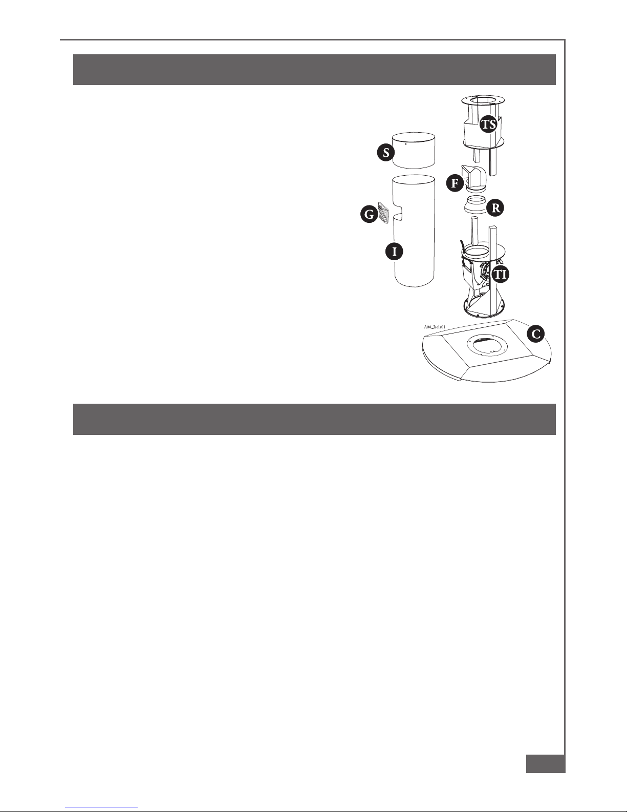
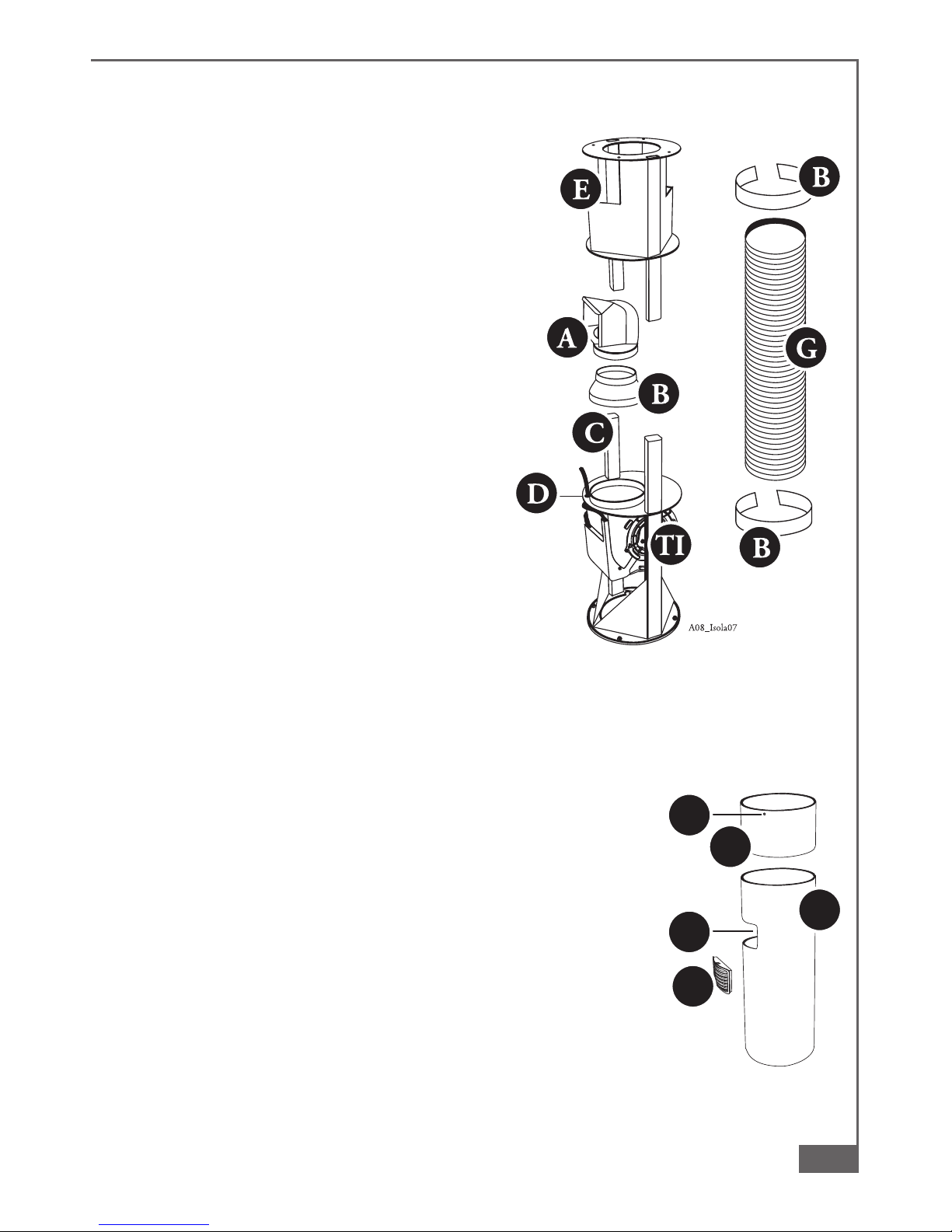
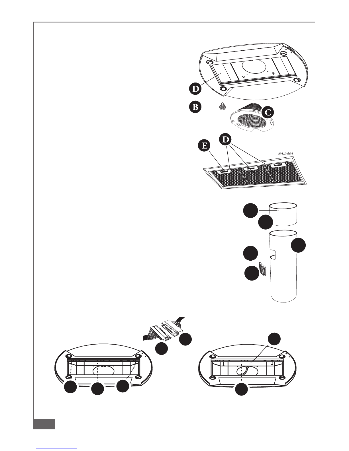
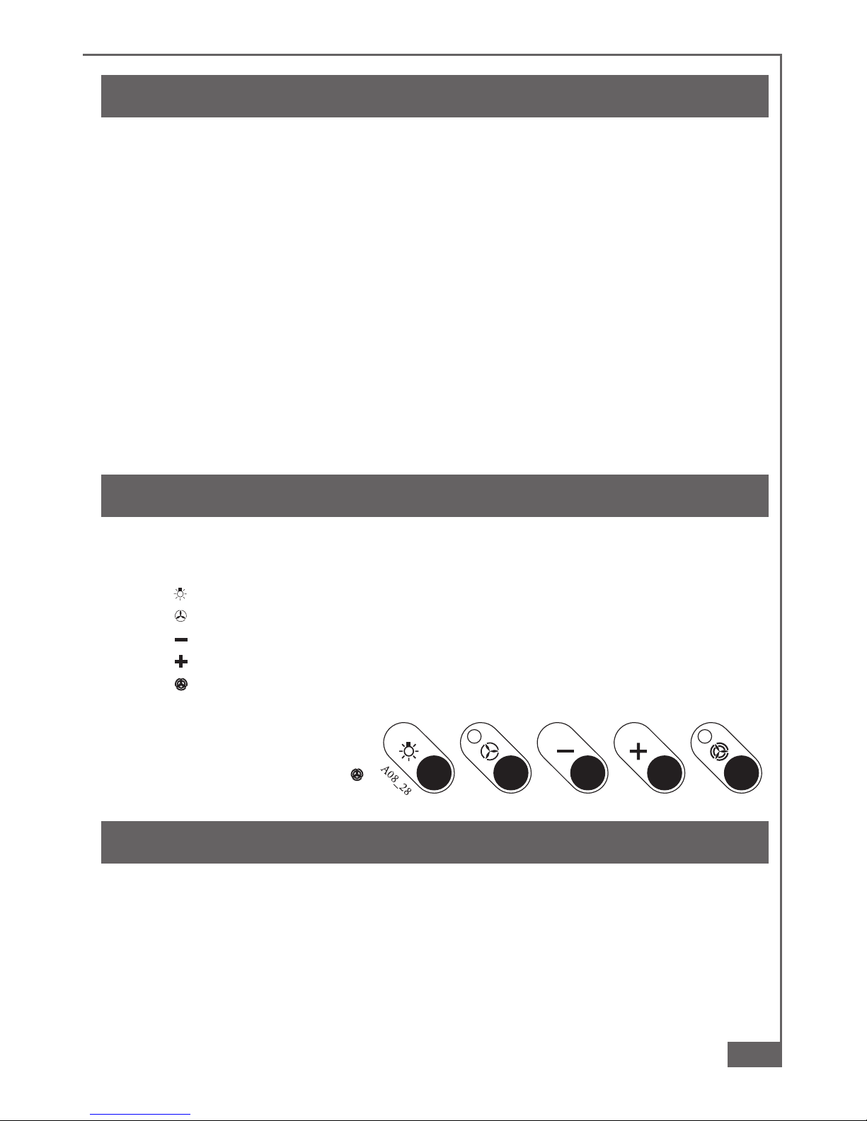
Küppersbusch DX ISLA User manual

Küppersbusch
Küppersbusch EDIP 6650.0 User manual

Küppersbusch
Küppersbusch EMI 850.0E User manual

Küppersbusch
Küppersbusch IKD 9210.1 GE Operation manual

Küppersbusch
Küppersbusch EMA 800.0W User manual

Küppersbusch
Küppersbusch Hood User manual

Küppersbusch
Küppersbusch IKD9885.0 Operator's manual

Küppersbusch
Küppersbusch D633.1 Quick setup guide

Küppersbusch
Küppersbusch IKD9890.0 Quick setup guide

Küppersbusch
Küppersbusch IKD 908.1 Quick setup guide

Küppersbusch
Küppersbusch 55 cm User manual

Küppersbusch
Küppersbusch IKD 937.0 GE User manual

Küppersbusch
Küppersbusch KD.. 9700.0GE User manual

Küppersbusch
Küppersbusch KD 9550 User manual

Küppersbusch
Küppersbusch KD 9850.0 Technical manual

Küppersbusch
Küppersbusch IKD3850.0E Operator's manual

Küppersbusch
Küppersbusch KD 6600 User manual

Küppersbusch
Küppersbusch IKD9880.0 Quick setup guide


Popular Ventilation Hood manuals by other brands

Gorenje
Gorenje S3 IHGC963S4X manual

KOBE
KOBE ISX2136SQB-1 Installation instructions and operation manual

U.S. Products
U.S. Products ADVANTAGE-100H Information & operating instructions

Kuppersberg
Kuppersberg DUDL 4 LX Technical Passport

Framtid
Framtid HW280 manual

Thermador
Thermador HGEW 36 FS installation manual