K-Tool PRO Series Instructions for use

Capacity
1000 Lbs
1000 Lbs
2000 Lbs
2000 Lbs
Printed in Taiwan
KTI-63503-M0 rev 08/06
Transmission Jacks
K-Tool International
31111 Wixom Rd., Wixom, MI 48393
E-mail: [email protected]
(248) 669-5000
Operating Instructions
& Parts Manual
Model KTI-63505
Model KTI-63511
Model KTI-63504
Model Number
KTI-63503
KTI-63504
KTI-63505
KTI-63511
(Air/ Manual)

2
ONE YEAR LIMITED WARRANTY
For a period of one (1) year from date of purchase, KTI will repair or replace, at its option, without charge, any
of its products which fails due to a defect in material or workmanship under normal usage. This limited warranty is a
consumer's exclusive remedy.
Performance of any obligation under this warranty may be obtained by returning the warranted product, freight
prepaid, to K-Tool International 31111 Wixom Rd. Wixom, MI 48393, phone (248)669-5000.
Except where such limitations and exclusions are specifically prohibited by applicable law, (1) THE
CONSUMER'S SOLE AND EXCLUSIVE REMEDY SHALL BE THE REPAIR OR REPLACEMENT OF DEFECTIVE
PRODUCTS AS DESCRIBED ABOVE. (2) KTI SHALL NOT BE LIABLE FOR ANY CONSEQUENTIAL OR INCIDENTAL
DAMAGE OR LOSS WHATSOEVER. (3) ANY IMPLIED WARRANTIES, INCLUDING WITHOUT LIMITATION THE
IMPLIED WARRANTIES OF MERCHANTABILITY AND FITNESS FOR A PARTICULAR PURPOSE, SHALL BE LIMITED
TO ONE YEAR, OTHERWISE THE REPAIR, REPLACEMENT OR REFUND AS PROVIDED UNDER THIS EXPRESS
LIMITED WARRANTY IS THE EXCLUSIVE REMEDY OF THE CONSUMER, AND IS PROVIDED IN LIEU OF ALL
OTHER WARRANTIES, EXPRESS OR IMPLIED. (4) ANY MODIFICATION, ALTERATION, ABUSE, UNAUTHORIZED
SERVICE OR ORNAMENTAL DESIGN VOIDS THIS WARRANTY AND IS NOT COVERED BY THIS WARRANTY.
Some states do not allow limitations on how long an implied warranty lasts, so the above limitation may not
apply to you. Some states do not allow the exclusion or limitation of incidental or consequential damages, so the above
limitation or exclusion may not apply to you. This warranty gives you specific legal rights, and you may also have other
rights which vary from state to state.
K-Tool International
248-669-5000

3
Save these instructions. For your safety, read, understand, and follow the information provided with and on this jack.
The owner and operator of this equipment shall have an understanding of this jack and safe operating procedures before
attempting to use. The owner and operator shall be aware that use and repair of this product may require special skills
and knowledge. Instructions and safety information shall be conveyed in the operator's native language before use of
this jack is authorized. If any doubt exists as to the safe and proper use of this jack, remove from service immediately.
Inspect before each use. Do not use if broken, bent, cracked or damaged parts are noted. Any jack that appears
damaged in any way, or operates abnormally shall be removed from service immediately. If the jack has been or
suspected to have been subjected to a shock load (a load dropped suddenly, unexpectedly upon it), immediately
discontinue use until jack has been checked by an KTI authorized service center. It is recommended that an annual
inspection be done by qualified personnel. Labels and Owner's Manuals are available from manufacturer (see Replacement
Parts section).
PRODUCT DESCRIPTION
KTI Transmission Jacks are designed to be used as an aid in the removal and installation of vehicle component parts
and assemblies, specifically transmissions. Model Nos. KTI-63503, KTI-63504 and KTI-63505 are for use under an
overhead lift or in a garage pit. The air actuated function is an added feature of Model No. KTI-63504. Model No. KTI-
63511 is for use under portable lift equipment, where vehicle must be supported by appropriately rated jack stands. With
Model KTI-63504, ensure that your air source can dedicate 7.8 CFM @ 90 - 175 PSI to each jack operated. To ensure
dependable, trouble free operation an air dryer and oiler is recommended.
Product appearance may differ slightly from this publication due to improvements in manufacturing, design
and materials. However, performance characteristics will not be adversely affected.
SPECIFICATIONS
Model Capacity Base Size ( L x W ) Min. Height Max. Height
1000 Lbs 33-1/8" x 35-1/2" 37-7/8" 77-5/8"
1000 Lbs 34-1/8" x 36-1/8" 37-7/8" 77-5/8"
2000 Lbs 39-3/8" x 19-1/8" 7-7/8" 33-1/2"
KTI-63503
KTI-63504
KTI-63511
48-5/8"
KTI-63505 2000 Lbs
42-1/8" x 39-1/2" 77-3/8"

ASSEMBLY (KTI-63503, KTI-63504)
Refer to figure 1:
1. Three major parts should be included in package:
(a) Hydraulic unit with pumping mechanism ( air motor
equipped for model 63504),
(b) saddle unit, and
(c) 2 pieces of base half with hex socket bolts and
washers.
2. Attach either one of the two base halves to the base
of the hydraulic unit, then secure using allen head
bolts and washers provided. Then apply the same
procedure to the other base frame. Use torque wrench
to tighten to 30 lb.ft. Do not overtighten.
3. Position the saddle unit above the ram piston, place
the saddle socket onto the ram piston. Secure using
the set screw .
Note: Before initial use, turn vent screw counterclockwise
carefully, but no more than 1 full turn.
4
Note: Vent Screw and Oil Filler Screw are located on
the upper portion of the reservoir. See exploded drawing
on pages 8 and 9.
ASSEMBLY (KTI-63505)
Refer to figure 2:
1. Three major parts should be included in package:
(a) Hydraulic unit with pumping mechanism,
(b) saddle unit, and
(c) 2 pieces of base half with hex socket bolts and
washers.
2. Attach either one of the two base halves to the base
of the hydraulic unit, then secure using allen head
bolts and washers provided. Then apply the same
procedure to the other base frame. Use torque wrench
to tighten to 30 lb.ft. Do not overtighten.
3. Attach the brackets to reservoir, then attach one end
of the suppor bar to base half and the other end to the
bracket. Secure with bolts and nuts provided. Repeat
for all other three support bars.
4. Slice the position handle to reservoir from top, then
secure with bolts and nuts provided.
5. Position the saddle unit above the ram piston, place
the saddle socket onto the ram piston. Secure using
the set screw.
6. Remove oil filler screw. This will allow any pressurized
air to escape.
7. Ensure oil level is just below the rim of the oil filler
screw hole. Reinstall the oil filler screw.
Note: Before initial use, turn vent screw counterclockwise
carefully, but no more than 1 full turn.
Figure 2 - Model KTI-63505 Components
Note: Vent Screw and Oil Filler Screw are located on
the upper portion of the reservoir. See exploded drawing
on page 10.
Figure 1 - Model KTI-63503 & KTI-63504 Components
air motor
(Model KTI-63504)
air pump pedal
(Model KTI-63504)
oil filler screw
(not shown)
vent screw
(not shown)
swivel caster
base half
reservoir
air supply inlet
(not shown)
saddle
assembly
release valve
position handle
tilt adjustment
knobs
foot pump
pedal
saddle assembly
caster
base half
foot pump
pedal
oil filler screw
(not shown)
air vent screw
(not shown)
tilt adjustment
knobs
position handle
support bar bracket
release valve

5
Note: Oil Filler Plug is rubber and located centrally on
the upper portion of the reservoir. See exploded drawing
on page 11.
Figure 3 - Model KTI-63511
release valve
saddle
assembly
tilt adjustment
knobs
position handle
oil filler plug
(not shown)
swivel caster
pump
handle
chain
handle
sleeve
lift arm
ASSEMBLY (KTI-63511)
Refer to figure 3:
Little or no assembly is required. Refer to figure 3 and
the exploded view on page 11 for details in understanding
the assembly and the nomenclature of your product.
BEFORE USE
1. Inspect jack before each use. Do not use if bent,
broken or cracked components are noted. Ensure that
casters move freely. Check for and tighten any loose
assemblies.
2. Verify that the product and the application are
compatible.
3. With ram fully retracted, locate and remove the oil
filler plug/screw. This will help release any pressurized
air which may be trapped within the reservoir. Ensure
the oil level is just below the oil filler plug/screw hole.
Reinstall the oil filler plug/screw.
For KTI-63511 only: Ensure the oil level is ~3/16"
above the inner cylinder as seen from the oil filler plug
hole.
4. Before initial use, turn vent screw counterclockwise
carefully, but no more than 1 full turn.
5. KTI-63504 only: Pour a teaspoon of good quality, air
tool lubricant into the air supply inlet of the lift control
valve (See Fig 1). Connect to air supply and operate
for 3 seconds to evenly distribute lubricant.
Note: Air actuated product is fitted to accept the popular
1/4"npt air nipple. When installing air nipple, ensure that
thread sealing compound enter the air supply inlet orifice.
Application of thread tape is acceptable, but ensure that
it is not applied beyond the first machine thread.
• Study, understand, and follow all printed materials
provided with/on this product before use.
• Do not exceed rated capacity.
• Use only on hard, level surfaces capable of
supporting rated capacity loads.
• Use of this jack is limited to the removal,
installation and transportation of transmissions,
transfer cases and transaxles.
• Do not use a transmission jack to tilt or support a
vehicle.
• Ensure the center gravity of load is centered on the
saddle.
• Do not exceed 10
0
tilt angle of the saddle assem-
bly in all directions.
• Adequately support the vehicle before starting re-
pairs.
• Use only chains and slings provided.
• If loaded jack must be moved, make sure that the
load is secured, stable and in lowest position.
• This is a lifting and lowering device only.
• Transfer load immediately to appropriate support
device for service or repair.
• Shock loads may cause the sudden loss of load
and/ or cause the jack to tip or flip over violently,
bend or break.
• No alterations shall be made to this product
• Failure to heed these markings may result in
personal injury and/or property damage.
!
WARNING
To avoid crushing and related
injuries:
NEVER work on, under or
around a load supported only
by a jack. Immediately
transfer the load to an
appropriate work station.
!WARNING
• Leer, comprender, y seguir las instrucciónes antes de
utilizar el aparato.
• El manual de instrucciónes y la información de
seguridad deben estar comunicado en lengua del
operador antes del uso.
• No seguir estas indicaciónes puede causar daños
personales o materiales.
!ADVERTENCIA

6
REPLACEMENT PARTS
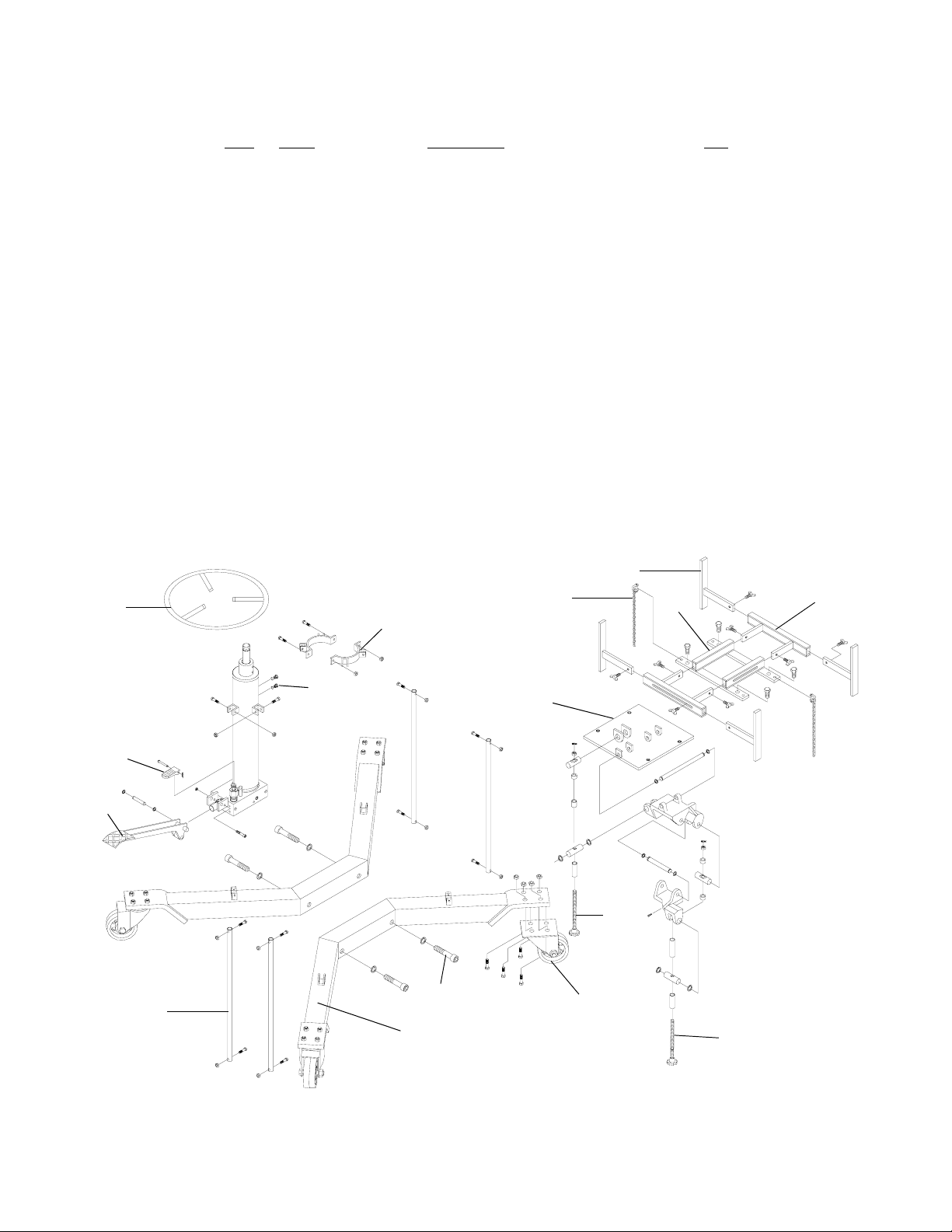
Available Parts: Please refer to the Parts drawings on
page 8 thru 11 when ordering parts. Not all components
of the jack are replacement items, but are illustrated as
a convenient reference of location and position in the
assembly sequence. When ordering parts, give Model
No. and the description. To order parts contact KTI at
MAINTENANCE
Important: Use only a good grade hydraulic jack oil. Avoid
mixing different types of fluid and never use brake fluid,
turbine oil, transmission fluid, motor oil or glycerin. Im-
proper fluid can cause failure of the jack and the potential
for sudden and immediate loss of load. Fill with good quality
jack oil. We recommend Mobil DTE 13M or equivalent.
Adding oil
For Models KTI-63503, KTI-63504 & KTI-63505:
1. With saddle fully lowered, and jack in its upright, level
position. Remove oil filler screw.
2. Fill with oil until just below the rim of the oil filler screw
hole. Reinstall the oil filler screw.
For Model KTI-63511:
1. With saddle fully lowered, remove oil filler plug.
2. Fill to ~3/16" above the inner cylinder as seen from the
oil filler plug hole. Reinstall oil filler plug.
Changing oil
For best performance and longest life, replace the
complete fluid supply at least once per year.
Note: Dispose of hydraulic fluid in accordance with
local regulations.
For Models KTI-63503, KTI-63504 & KTI-63505:
1. With saddle fully lowered, remove the oil filler screw.
2. Lay the jack on its side and drain the fluid into a
suitable container.
3. Fill with oil until just below the rim of the oil filler screw
hole. Reinstall the oil filler screw.
For Model KTI-63511:
1. With saddle fully lowered, remove oil filler plug.
2. Lay the jack on its side and drain the fluid into a
suitable container.
3. Fill to ~3/16" above the inner cylinder as seen from
the oil filler plug hole. Reinstall oil filler plug.
Lubrication
1. A periodic coating of light lubricating oil to pivot points,
axles and hinges will help to prevent rust and assure
that wheels, casters and pump assemblies move
freely.
2. When used on a daily basis, air pump models should
be internally lubricated before each use. Use only
good quality air tool lubricant. If no inline oiler is used,
pour a teaspoon of air tool oil into the inlet of the air
control valve. Simply operate the jack using the air
feature in order to fully distribute the oil.
Cleaning
Periodically check the ram for signs of rust or corrosion.
Clean as needed and wipe with an oily cloth.
Note: Never use sandpaper or abrasive material on
these surfaces !
Storage
When not in use, store the jack with ram fully retracted
and air supply disconnected.
OPERATION
Raise saddle
For Models KTI-63503, KTI-63504 & KTI-63505:
Caution! For Model KTI-63504, do not operate the jack
by pumping the lift pedal and pressing the air pump pedal
at the same time.
a. Pump foot pedal or press air pump pedal until saddle
reaches desired position.
b. Follow vehicle manufacturers recommended procedures
for removing the load as outlined in vehicle service
manual or repair guide.
c. Secure load with provided restraints. Ensure load's center
of gravity is centered on the saddle and load is stable
before moving jack.
For Model KTI-63511:
Locate and close release valve by turning knob clockwise
firmly, then pump the pump handle until the load is
contacted.
Lower saddle
Caution! Be sure all tools and personnel are clear before
lowering load.
For Models KTI-63503, KTI-63504 & KTI-63505:
Slowly, gently apply downward pressure to the release valve
pedal.
For Model KTI-63511:
Slowly, gently turn the release valve knob
counterclockwise, NEVER MORE THAN 1/2 FULL TURN
until the load is completely lowered.
Note: Dynamic shock loads are created by quickly opening
and closing the release valve as the load is being lowered,
The resulting overload may cause hydraulic system failure.
MAINTENANCE (continued)

TROUBLESHOOTING
7
Possible Causes Corrective Action
Jack will not lift load
Jack bleeds off after lift
Jack will not lower after unload-
ing
Poor lift performance
Will not lift to full extension
• Air supply inadequate
(Model KTI63504 only)
• Hydraulic unit malfunction
• Overload condition
• Hydraulic unit malfunction
• Reservoir overfilled
• Linkage binding
• Fluid level low
• Fluid level low
• Ensure adequate air supply (Model
KTI63504 ony)
• Contact KTI Tech. Service
• Remedy overload condition
• Contact KTI Tech. Service
• Drain fluid to proper level
• Clean and lubricate moving parts
• Ensure proper fluid level
Symptom

1
2
10
11
5, 6
7
8
9
4
3
12
13
Item Part# Description Qty
1 324-4-1900-208 Screw Assembly 2
2 G36-6-1804-102 Vent Screw Assembly 1
3 G36-3-1900-100 Lift Pedal 1
4 G36-6-1809-102 Release Valve Pedal 1
5 G36-3-5000-104 Caster w/o Brake 2
6 G36-3-5001-106 Caster w/ Brake 2
7 G36-3-2300-101 Tilt Screw Assembly 1
8 G36-3-2301-103 Tilt Screw Assembly 1
9 G36-3-0513-108 Accessory Kit 2
10 G36-4-4200-10308 Saddle Assembly (chain not included) 1
11 G36-3-0511-104 Bolt Set 1
12 G36-3-3301-108 Base Half 2
13 G36-3-2100-103 Handle Assemlby 1
- G36-3-9902-104 Repair Kit for Hydraulic Unit -
Replacement parts for Model KTI-63503
8
Figure 4 - Replacement Parts Illustration for Model KTI-63503

1
2
10
11
5, 6
7
8
9
4
3
12
4
14
15
16
17
13
Figure 5 - Replacement Parts Illustration for Model KTI-63504
9
Replacement parts for Model 63504
Item Part# Description Qty
1 324-4-1900-208 Screw Assembly 2
2 G36-6-1804-102 Vent Screw Assembly 1
3 G36-3-1900-100 Lift Pedal 1
4 G36-6-1809-102 Release Valve/ Air Pump Pedal 2
5 G36-3-5000-104 Caster w/o Brake 2
6 G36-3-5001-106 Caster w/ Brake 2
7 G36-3-2300-101 Tilt Screw Assembly 1
8 G36-3-2301-103 Tilt Screw Assembly 1
9 G36-3-0513-108 Accessory Kit 2
10 G36-4-4200-10308 Saddle Assembly (chain not included) 1
11 G36-3-0511-104 Bolt Set 1
12 G36-3-3301-108 Base Half 2
13 G36-3-2100-103 Handle Assembly. 1
14 A24-6-8101-107 Male Coupler 1
15 G36-4-2000-105 Air Motor 1
16 G36-6-2302-103 Hose Connector 2
17 G36-6-2300-109 Air Hose 1
- G36-3-9902-104 Repair Kit for Hydraulic Unit -

10
1
2
13
89, 10
11
12
14
5
4
6
3
7
15 16
17
Replacement parts for Model 63505
Item Part# Description Qty
1 324-4-1900-208 Screw Assembly 2
2 G37-3-1320-109 Bracket 2
3 G37-3-1806-105 Handle 1
4 G36-3-1900-100 Lift Pedal 1
5 G36-6-1809-102 Release Valve Pedal 1
6 G37-6-1319-102 Support Bar 4
7 G37-3-3300-103 Base Half 2
8 651-1-0127-100 Bolt 4
9 G37-4-5200-105 Caster w/o Brake 2
10 G37-4-5201-107 Caster w/ Brake 2
11 G36-3-2300-101 Tilt Screw Assembly 1
12 G36-3-2301-103 Tilt Screw Assembly 1
13 G37-3-4200-104 Saddle Plate 1
14 G52-4-4102-101 Chain & Hook 2
15 G37-3-2903-209 Saddle Support Bar 4
16 G37-3-2902-207 Saddle Adjustable Bracket 2
17 G37-3-2901-205 Saddle Support Seat 1
- G37-3-9901-109 Repair Kit for Hydraulic Unit -
Figure 6 - Replacement Parts Illustration for Model KTI-63505

11
Figure 7 - Replacement Parts Illustration for Model KTI-63511
Item Part# Description Qty
1 505-9-0092-207 Oil Filler Plug 1
2 G52-1-1000-100 Hydraulic Unit 1
3 G36-6-7000-102 Chain 2
4 G52-3-4204-103 Saddle Assembly 1
5 G52-6-4207-107 Angle Bar 2
6 G52-6-4402-105 Tilt Screw 1
7 G52-6-4401-103 Tilt Screw 1
8 G52-6-1709-106 Tilt Knob 2
9 G52-3-4300-109 Saddle Holder 1
10 G52-4-5200-106 Caster Assembly 4
11 G52-3-9903-104 Handle 1
12 G52-6-1701-100 Release Valve 1
13 G34-6-1709-104 Release Valve Knob 1
14 G52-6-3004-108 Position Handle 1
15 653-1-0127-409 Hex. Bolt 6
16 653-1-0159-008 Hex. Bolt 1
- G52-3-9901-100 Repair Kit for Hydraulic Unit -
1
2
4
3
13
7
6
10
9
5
8
8
11
12
14
15
15
16
Replacement parts for Model 63511
Other manuals for PRO Series
1
This manual suits for next models
4
Table of contents
Other K-Tool Jack manuals

K-Tool
K-Tool XD KTI63101 User manual

K-Tool
K-Tool KTI-63105A User manual

K-Tool
K-Tool KTI-63131B User manual

K-Tool
K-Tool KTI63105 User manual

K-Tool
K-Tool XD KTI-63133A User manual

K-Tool
K-Tool KTI63100 User manual

K-Tool
K-Tool KTI-63517A User manual

K-Tool
K-Tool KTI63092 User manual

K-Tool
K-Tool KTI63500 User manual

K-Tool
K-Tool KTI63131A User manual