manuals.online logo
Brands
  1. Home
  2. •
  3. Brands
  4. •
  5. KI
  6. •
  7. Office Equipment
  8. •
  9. KI Laptop Garage Manual

KI Laptop Garage Manual

Installation & Operating Instructions
Laptop Garage®
February 2015
Assemble units as described herein only. To do otherwise
may result in instability. All screws, nuts and bolts must be
tightened securely and must be checked periodically after
assembly. Failure to assemble properly, or to secure parts
may result in assembly failure and personal injury.
WorkZone desks for required
specific assembly of these desk
systems, and complete all desk
assembly prior to completing
these set-up instructions.
Remote Lock Option Installation
Note: If your Laptop Garage unit
does not have the remote lock
option, skip now to the “Release
Lever Operation” section, page 3.
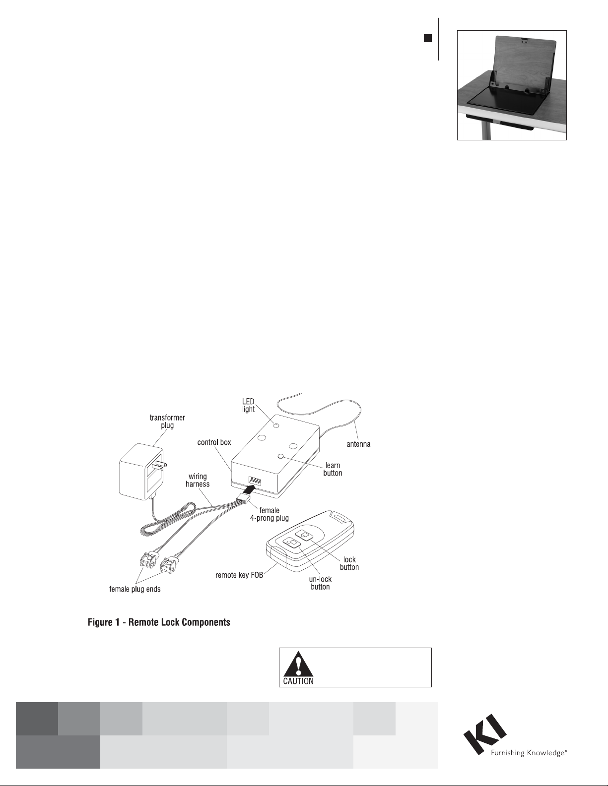
1. Locate the remote lock
components (see Figure 1).
Carefully plug the white female
4-prong plug of the white wire
harness onto the four male
prongs on the side of the control
box (Figure 1).
2. Place the control box with
attached wiring harness/
transformer plug into the
wireway or modesty panel of
desk. Route the transformer plug
toward a power source, but do
NOT connect it to power until
instructed (Figure 1).
3. The installed Laptop Garage unit
has a remote lock wire which runs
from the solenoid lock at the front
(Figure 2), goes under the shelf
of the unit, and out the back of the
Laptop Garage unit. Locate that
remote lock wire and plug it into
one of the two female plug-ends
of the control box wiring harness.
If the desk has a second Laptop
Garage unit, attach its remote lock
wire into the second female plug
end of the control box at this time
(Figures 1 & 2).
Caution: Make sure that any
excess remote lock wire, from the
solenoid lock is routed outside of
the Laptop Garage housing so it
does not become tangled in the
moving mechanism.
Remote Lock Programming and
Operation
Note: The remote lock control
box requires programming and
can be re-programmed if lock is
experiencing problems.
1. Connect the control box
transformer plug to a power
source and begin programming
by pressing the “learn button”
until the LED light turn from red
to green (Figure 1).
2. After the LED light turns green,
press the “lock button” on the
remote key FOB and then press
the “un-lock button” (Figure 1).
Press buttons again to verify that
the key FOB correctly controls the
solenoid mechanism to lock or
un-lock the Laptop Garage unit.
Note: The following instructions
cover the optional remote lock
components, general
programming & operation, as
well as proper installation of a
laptop computer into the Laptop
Garage unit. The Laptop Garage
unit comes factory-installed
into worksurfaces; please refer
to instructions for InTandem or
2
Laptop Garage®
Installation & Operating Instructions
Assemble units as described herein only. To do otherwise
may result in instability. All screws, nuts and bolts must be
tightened securely and must be checked periodically after
assembly. Failure to assemble properly, or to secure parts
may result in assembly failure and personal injury.
3. After programming is complete,
press the “unlock” button found
on the key FOB. Within two
minutes, push down lightly
on the front center of the door,
allowing the lock pin to retract
and the door front to open
approximately 2". Then grasp
the open edge of the door and
rotate to the full open position.
Note: The lock must be
pressed on the key FOB to
re-lock the closed Laptop
Garage.
4. To close the unit, grasp the
top or sides of the door and
rotate closed until the door is
still open approximately 2".
Firmly push down on the front
center of the door until the latch
engages the lock. The “lock”
button on the key FOB may
need to be pressed in order for
the door to remain locked.
Adjustment of Components
5. The solenoid latch on the door,
or the lock solenoid in the
front panel can be adjusted if
necessary to ensure the top
of the door is flush with the
top of the worksurface when
closed and that the lock pin
engages the latch properly.
To adjust the latch, loosen the
two wood screws that attach
it to the door (Figure 2), and
slide toward front or back of
door, then re-tighten screws. To
adjust the height of the solenoid
lock, remove the two screws
attaching the solenoid cover to
the front cover and worksurface.
Use the solenoid wrench and
an adjustable wrench, loosen
the lock solenoid nut and adjust
the lock up or down. Retighten
the nut and replace the solenoid
cover (Figure 2).
Note: It may be necessary to
open and close the unit multiple
times to ensure proper lock
operation. The front panel can
also be removed to access the
solenoid lock by removing the
two outer screws attaching the
front panel to the worksurface.
Laptop Garage®
Installation & Operating Instructions
Assemble units as described herein only. To do otherwise
may result in instability. All screws, nuts and bolts must be
tightened securely and must be checked periodically after
assembly. Failure to assemble properly, or to secure parts
may result in assembly failure and personal injury.
3
Release Lever Operation
1. Open the Laptop Garage door
by pressing the release lever
located under the worksurface
near the center front of the unit.
Allow the door front to open
approximately 2" and grasp the
open edge of the door and rotate
to the open position. To close
the unit, grasp the top of the top
or sides of the door and rotate
closed until the door is open
approximately 2". Firmly push
down on the front center of door
until the door latch engages the
release lever (Figure 3).
2. The latch on the door can be
adjusted if necessary to ensure
the top of the door is flush with
the top of the worksurface when
closed. To adjust the latch,
loosen the two wood screws that
attach it to the door and slide
toward front or back of door.
Re-tighten screws.
Laptop Computer Installation
Note: It is important that
all wiring and cables be
routed appropriately to avoid
interference with Laptop Garage
mechanism and cause damage.
Dual lock patches (Figure 2) will
also help to stabilize and locate
the laptop computer inside the
Laptop Garage unit while still
allowing easy removal when
required.
1. Open the Laptop Garage per the
previous instructions. Peel the
adhesive protection off one side
of the dual lock patch (Figure 2)
and install to a flat location on
a bottom corner of the laptop
computer. Remove the adhesive
protection from the underside of
the dual lock patch and carefully
position the laptop computer
onto the Laptop Garage shelf so
it will not interfere with the unit's
opening or closing. Next, lift the
laptop computer up, splitting
the one fully-secured dual
lock patch between the shelf
and the computer and remove
the adhesive protection from
the remaining three dual lock
patches. Carefully set the laptop
computer back into its correct
position and press down firmly
to seat the dual lock patches to
the shelf (Figure 2).
2. Laptop power and data wiring
can now be run through the
holes or lay-in notches in the
laptop shelf (Figure 2). Ensure
that no wires are directly below
the laptop shelf or near the
door pivot brackets on each
side. Secure extra wiring to the
underside of the worksurface or
unit with nylon wire ties or place
in electrical beam of desk.
1330 Bellevue Street • P.O. Box 8100 • Green Bay, WI 54308-8100 • Tel 1-800-424-2432 • www.ki.com
© 2015 Krueger International, Inc. All Rights Reserved • Code KI-61738R3/KI/PDF/0215

Other KI Office Equipment manuals

KI Pull Out Worksurface Storage User manual

KI

KI Pull Out Worksurface Storage User manual

KI Tattoo Flex Screen User manual

KI

KI Tattoo Flex Screen User manual

KI WireWorks User manual

KI

KI WireWorks User manual

KI WireWorks User manual

KI

KI WireWorks User manual

KI WireWorks User manual

KI

KI WireWorks User manual

KI All Terrain Wall Rail User manual

KI

KI All Terrain Wall Rail User manual

KI Likha Casegoods User manual

KI

KI Likha Casegoods User manual

KI 810 User manual

KI

KI 810 User manual

KI WireWorks User manual

KI

KI WireWorks User manual

KI RoomScape User manual

KI

KI RoomScape User manual

KI Backbone Media Platform User manual

KI

KI Backbone Media Platform User manual

KI WireWorks User manual

KI

KI WireWorks User manual

Popular Office Equipment manuals by other brands

Master MP3 instruction manual

Master

Master MP3 instruction manual

Herman Miller Action Office Installation

Herman Miller

Herman Miller Action Office Installation

Koplus MILLI STAND Assembly instructions

Koplus

Koplus MILLI STAND Assembly instructions

Formax 6404 Series Operator's manual

Formax

Formax 6404 Series Operator's manual

Steelcase Avenir PAB-3 manual

Steelcase

Steelcase Avenir PAB-3 manual

ergochair AdaptLift user manual

ergochair

ergochair AdaptLift user manual

LDI SAFCO 3045 Assembly instructions

LDI

LDI SAFCO 3045 Assembly instructions

SnapCab Pod S installation instructions

SnapCab

SnapCab Pod S installation instructions

kube Kubebooth Kwe Assembly guide

kube

kube Kubebooth Kwe Assembly guide

Brother MFC-5460CN user guide

Brother

Brother MFC-5460CN user guide

bbf WC12923 manual

bbf

bbf WC12923 manual

Vicoustic VicOffice Desk Lat installation manual

Vicoustic

Vicoustic VicOffice Desk Lat installation manual

Extron electronics Retractor 2 Series installation guide

Extron electronics

Extron electronics Retractor 2 Series installation guide

Unisto Translex S1 HANDLING, CARE & SAFETY INSTRUCTIONS

Unisto

Unisto Translex S1 HANDLING, CARE & SAFETY INSTRUCTIONS

Anviz FacePass Pro user manual

Anviz

Anviz FacePass Pro user manual

Renz DTP DTP 340 M instruction manual

Renz

Renz DTP DTP 340 M instruction manual

Canon ColorPASS-Z5000 Color guide

Canon

Canon ColorPASS-Z5000 Color guide

Yaesu ZCUT-10 instruction manual

Yaesu

Yaesu ZCUT-10 instruction manual

manuals.online logo
manuals.online logoBrands
  • About & Mission
  • Contact us
  • Privacy Policy
  • Terms and Conditions

Copyright 2025 Manuals.Online. All Rights Reserved.