manuals.online logo
Brands
  1. Home
  2. •
  3. Brands
  4. •
  5. KI
  6. •
  7. Office Equipment
  8. •
  9. KI WireWorks User manual

KI WireWorks User manual

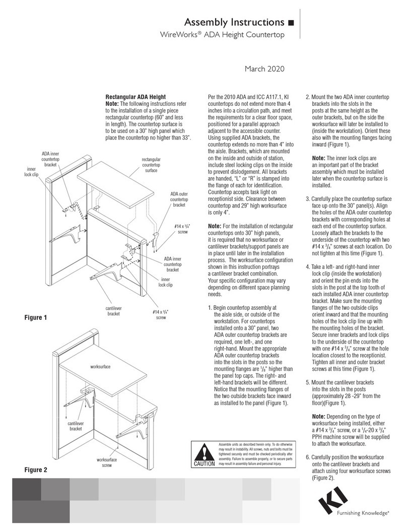
Assembly Instructions
WireWorks® Panel System
Off-Module Panel Components
July 2016
Assemble units as described herein only. To do otherwise
may result in instability. All screws, nuts and bolts must be
tightened securely and must be checked periodically after
assembly. Failure to assemble properly, or to secure parts
may result in assembly failure and personal injury.
1”
half post
off-module panel
top clamp
off-module panel
connector assembly
(OMPC)
WireWorks spine wall
clamping
screw
top
clamp
steel
horizontal
rail
off-module
top cap
top cap
trim
Off-Module Panel Connector
WireWorks Off-Module Panel Connector
(OMPC) allows a WireWorks panel to
be attached perpendicular at any point
along a WireWorks spine wall.
The OMPC and half post is factory
assembled. By design, the top of the
half post will be approximately 1”
higher than the top of the OMPC
(Figure 1).
1. Position the OMPC assembly at the
point where it is to be connected to
the WireWorks spine wall (Figure 2).
Note: The OMPC must be the same
height as the height of the horizontal
rail to which it attaches.
2. Loosen the clamping screw to allow
the top clamp to be inserted in the
reveal between tiles (Detail A).
3. While holding the OMPC upright,
insert the bottom clamp into the
reveal located directly above the
WireWorks raceway door. The clamp
must engage into the slot of the steel
horizontal rail (Detail B).
4. Check for plumb and tighten
clamping screw.
5. Adjust the glide so the post is
appropriately supported.
6. Install off-module top cap and trim
as shown in Figure 3. Note: Flat
aluminum trim does not have an
off-module top cap.
Figure 1
Figure 2
Figure 3
Detail A
Detail B
1330 Bellevue Street • P.O. Box 8100 • Green Bay, WI 54308-8100 • Tel 1-800-424-2432 • www.ki.com
© 2016 Krueger International, Inc. All Rights Reserved • Code KI-61506R2/KI/PDF/0716
WireWorks®Panel System - Off-Module Panel Components
Parts Diagram
Assemble units as described herein only. To do otherwise
may result in instability. All screws, nuts and bolts must be
tightened securely and must be checked periodically after
assembly. Failure to assemble properly, or to secure parts
may result in assembly failure and personal injury.
1 /”gap
3
4
between worksurface
and panel
WireWorks
spine wall
off-module bracket allows 6” of
vertical adjustment from 24” to 30”
(above finished floor)
clamping
screw
raceway
door
cantilever brackets hung from
off-module worksurface brackets
wireworks spine wall
off-module
panel connector
cantilever brackets hung
directly in panel slots
WireWorks wing wall
off-module
panel connector 1 /”gap between work
3
4
surface and panel
corner worksurface
cantilever bracket in
“end-of-run” position
standard
cantilever bracket in
“shared” position
1”
off-module
worksurface bracket
WireWorks Off-Module
Worksurface Bracket
Allows a worksurface to be attached
at any point along a WireWorks
spine wall. The bracket is spaced
away from the panel 3/4” to allow the
removal of tiles from the spine wall.
The use of these brackets will create
a 13/4” space between the rear edge
of the worksurface and the tile of the
spine wall (Figure 4).
1. Position the off-module bracket
at the point where it is to be
connected to the WireWorks
spine wall (Figure 4).
2. Corner worksurfaces can be
attached to the spine wall using
off-module connectors and
then connected directly to the
perpendicular wing wall using
cantilever brackets (Figure 5).
3. Loosen the clamping screw to
allow the top clamp to be inserted
into the reveal between tiles
(Detail C).
4. While holding the off-module
bracket upright, insert the bottom
clamp into the reveal located
directly above the WireWorks
raceway door. The clamp must
engage into the slot of the steel
horizontal rail (Detail D).
5. The position of the cantilever
bracket (under the worksurface)
when used to support two
“shared” worksurfaces is 1”
different than when used as an
“end-of-run” bracket (Figure 6).
6. Check for plumb and tighten
clamping screw.
7. Engage the teeth of the
worksurface cantilever brackets
into the vertical slots of the
off-module bracket.
8. Position the worksurface on the
cantilever in either the “shared”
or “end-of-run” position
(Figure 6).
9. Mark and drill pilot holes for
#14 x 1” tapping screw,
then install to underside of
worksurface.
Figure 4
Figure 5
Figure 6
Detail C
Detail D

Other manuals for WireWorks

5

Other KI Office Equipment manuals

KI All Terrain Wall Rail User manual

KI

KI All Terrain Wall Rail User manual

KI Backbone Media Platform User manual

KI

KI Backbone Media Platform User manual

KI Pull Out Worksurface Storage User manual

KI

KI Pull Out Worksurface Storage User manual

KI WireWorks User manual

KI

KI WireWorks User manual

KI Laptop Garage Manual

KI

KI Laptop Garage Manual

KI Tattoo Flex Screen User manual

KI

KI Tattoo Flex Screen User manual

KI 810 User manual

KI

KI 810 User manual

KI WireWorks User manual

KI

KI WireWorks User manual

KI Likha Casegoods User manual

KI

KI Likha Casegoods User manual

KI WireWorks User manual

KI

KI WireWorks User manual

KI RoomScape User manual

KI

KI RoomScape User manual

KI WireWorks User manual

KI

KI WireWorks User manual

Popular Office Equipment manuals by other brands

Vivo DESK-V133E instruction manual

Vivo

Vivo DESK-V133E instruction manual

Panasonic KXF-3V3C operating instructions

Panasonic

Panasonic KXF-3V3C operating instructions

Herman Miller Action Office Installation

Herman Miller

Herman Miller Action Office Installation

U-Line H-8379 manual

U-Line

U-Line H-8379 manual

BuzziSpace BuzziNest Booth owner's manual

BuzziSpace

BuzziSpace BuzziNest Booth owner's manual

AMQ Amobi installation guide

AMQ

AMQ Amobi installation guide

ALTUS CPC-8 installation instructions

ALTUS

ALTUS CPC-8 installation instructions

Plockmatic BM 82 Operation manuals

Plockmatic

Plockmatic BM 82 Operation manuals

Steelcase Sync manual

Steelcase

Steelcase Sync manual

SEGUE Sunrise VK-1906 manual

SEGUE

SEGUE Sunrise VK-1906 manual

Uplift Desk PDC005-TRAY Assembly instructions

Uplift Desk

Uplift Desk PDC005-TRAY Assembly instructions

Amazon B07DDDCMXD manual

Amazon

Amazon B07DDDCMXD manual

Honeywell 7222 owner's manual

Honeywell

Honeywell 7222 owner's manual

Plus M-5 user manual

Plus

Plus M-5 user manual

Powis Parker SM1 user manual

Powis Parker

Powis Parker SM1 user manual

OLG COSMIC SYSTEM STRAIGHTLINE installation guide

OLG

OLG COSMIC SYSTEM STRAIGHTLINE installation guide

Askia Kameleon K6 Assembly instructions

Askia

Askia Kameleon K6 Assembly instructions

Canon Paper Deck Unit-F1 Service manual

Canon

Canon Paper Deck Unit-F1 Service manual

manuals.online logo
manuals.online logoBrands
  • About & Mission
  • Contact us
  • Privacy Policy
  • Terms and Conditions

Copyright 2025 Manuals.Online. All Rights Reserved.