8
WireWorks®Panel System
Assembly Instructions
Assemble units as described herein only. To do otherwise
may result in instability. All screws, nuts and bolts must be
tightened securely and must be checked periodically after
assembly. Failure to assemble properly, or to secure parts
may result in assembly failure and personal injury.
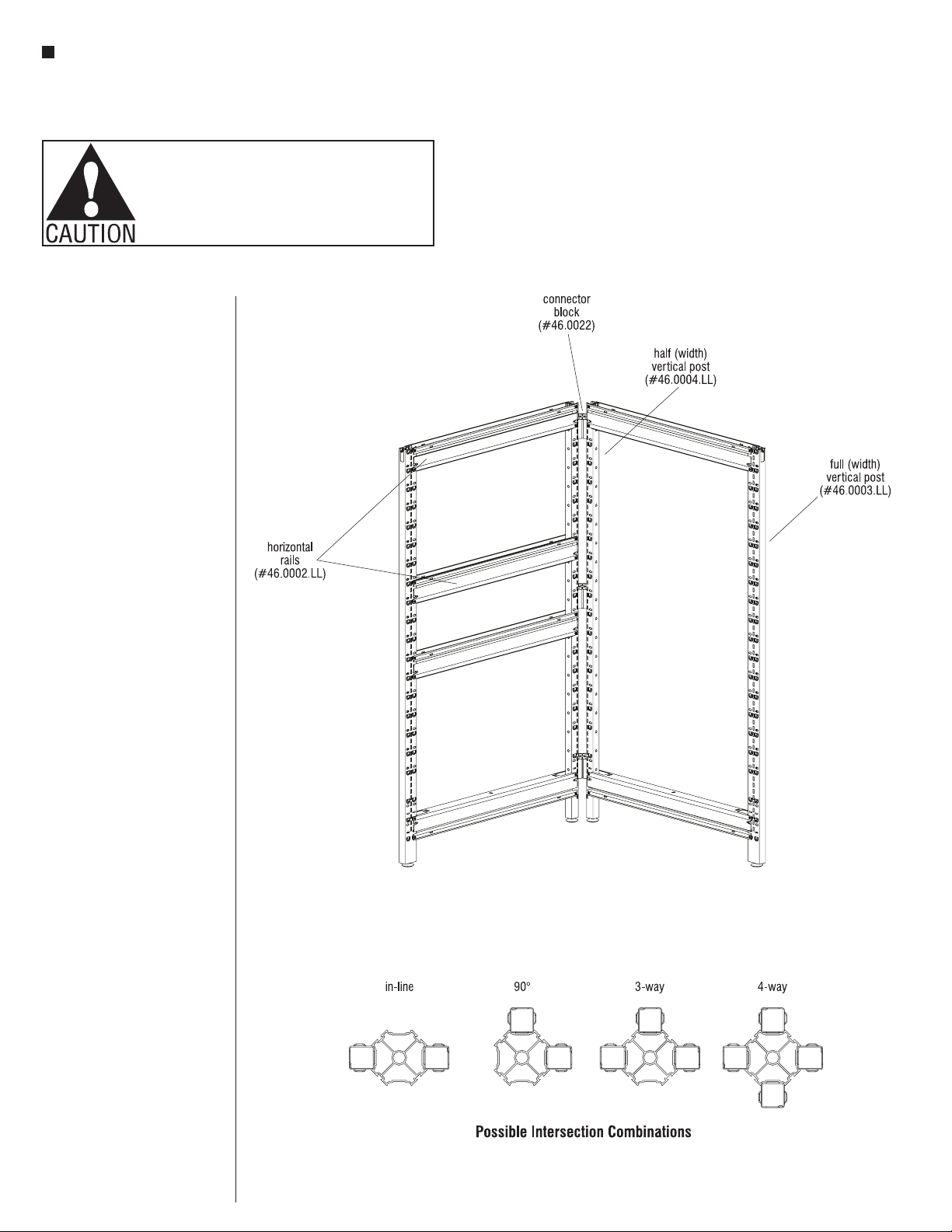
Attaching Horizontals To
Verticals
Horizontals are used at the top
and bottom of a panel to space
the vertical posts apart the
appropriate distance for the panel
width you are building. One rail is
used at the top of the panel with
the opening facing upward and
one rail is used at the bottom
facing downward. Panels that
are made up of more than one
tile also use horizontals at
intermediate heights (with the
opening facing up).
Note: Refer to the
space-planning layout and start
with a panel corner intersection,
building out in two directions so
the panel frame is able to stand
on its own.
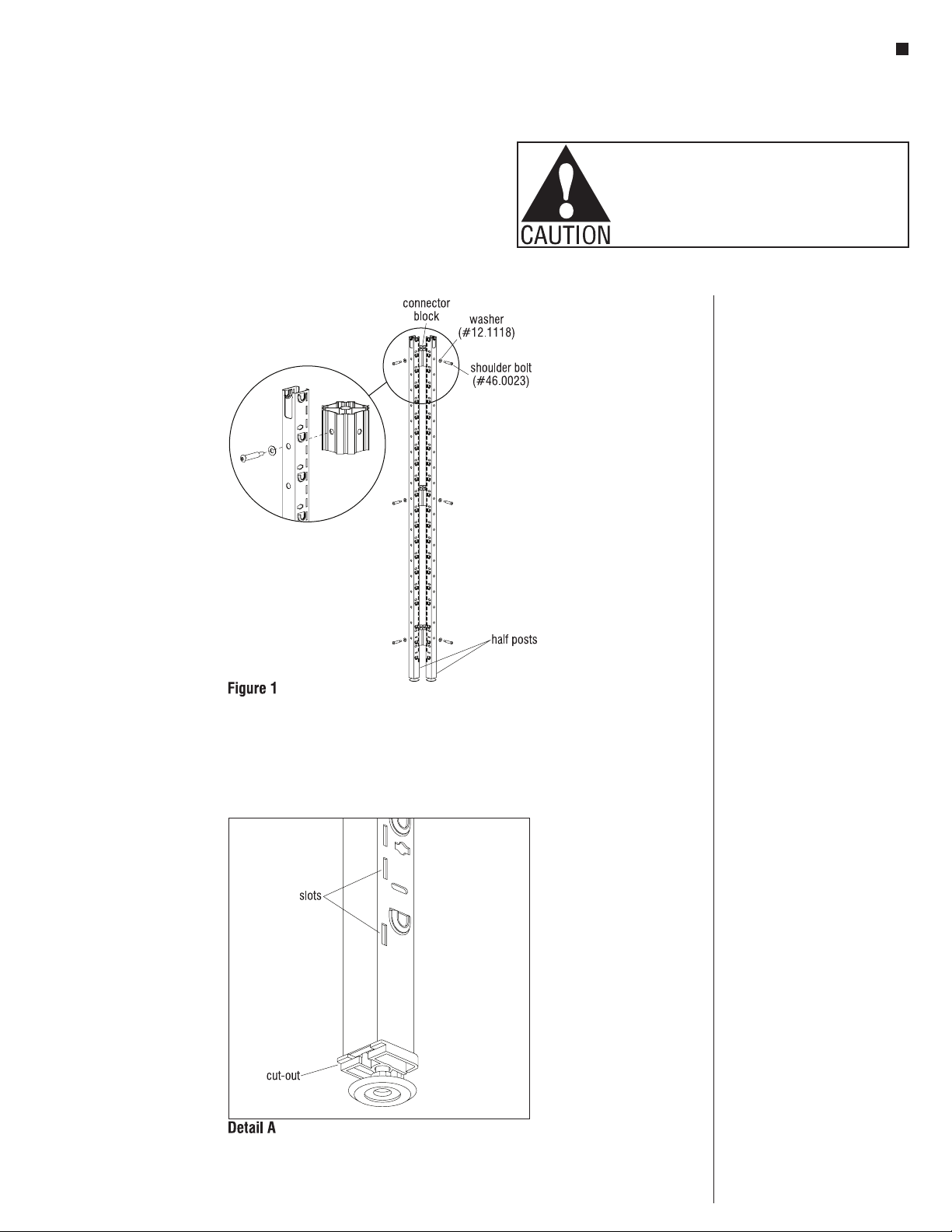
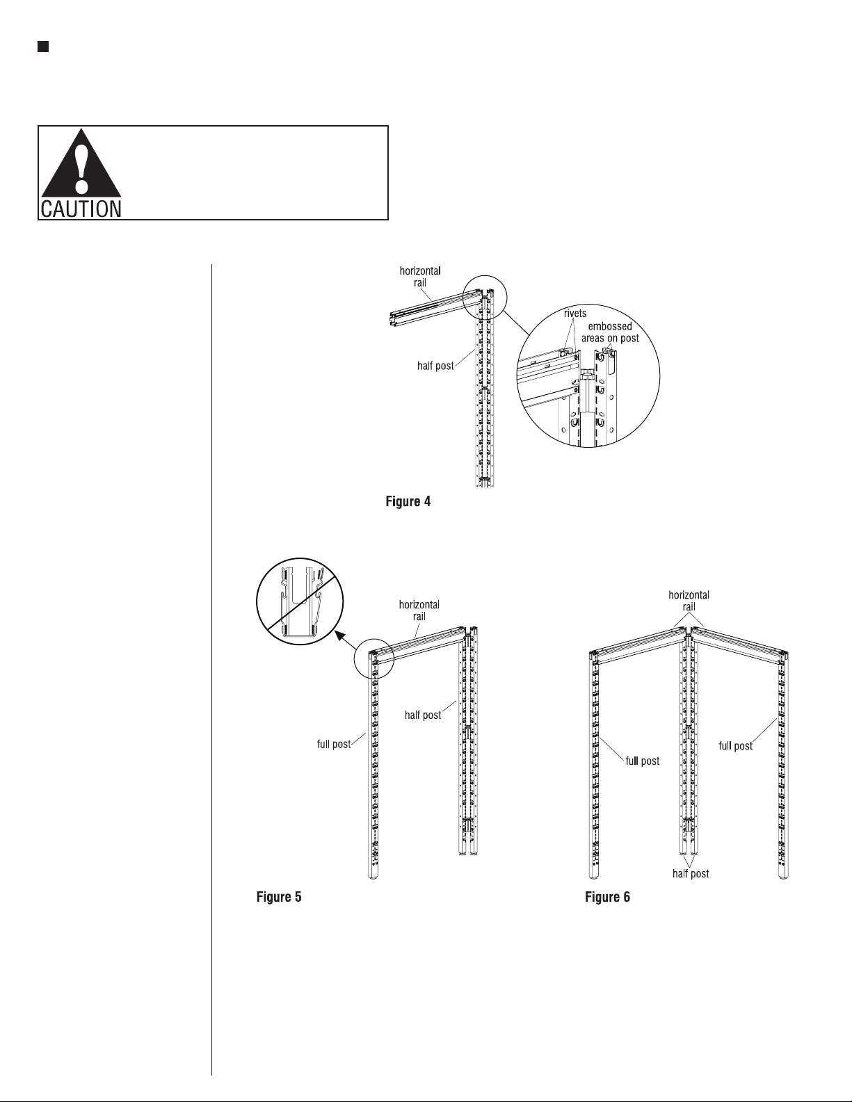
1. Slide a horizontal into the top of
a vertical half post with the rivets
above the pocket on the post.
Making sure all four rivets are
lined up with the corresponding
embosses, tap the horizontal into
place with a dead-blow style
mallet (Figure 4)
2. Referring again to the
space-planning layout, position
the appropriate vertical post
(full or half post) relative to
the horizontals and tap the
horizontals into place (Figure 5).
3. Repeat the above instructions,
building out in a direction
perpendicular to the first
horizontals from the corner post.
When this step is completed you
should have a partially assembled
90° corner that can support itself
(Figure 6).