manuals.online logo
Brands
  1. Home
  2. •
  3. Brands
  4. •
  5. Kontron
  6. •
  7. Computer Hardware
  8. •
  9. Kontron COMe-bP5020 User manual

Kontron COMe-bP5020 User manual

Other Kontron Computer Hardware manuals

Kontron AdvancedMC AM4211 User manual

Kontron

Kontron AdvancedMC AM4211 User manual

Kontron CP-RIO6-923 User manual

Kontron

Kontron CP-RIO6-923 User manual

Kontron AT8402 User manual

Kontron

Kontron AT8402 User manual

Kontron COMe-bID7 User manual

Kontron

Kontron COMe-bID7 User manual

Kontron USB-16REL User manual

Kontron

Kontron USB-16REL User manual

Kontron ePCI-201 User manual

Kontron

Kontron ePCI-201 User manual

Kontron AT8060 User manual

Kontron

Kontron AT8060 User manual

Kontron MOPSlcdGX1 User manual

Kontron

Kontron MOPSlcdGX1 User manual

Kontron MOPSlcdLX User manual

Kontron

Kontron MOPSlcdLX User manual

Kontron KTQ77/Flex User manual

Kontron

Kontron KTQ77/Flex User manual

Kontron cPCI-MXS64GX Product manual

Kontron

Kontron cPCI-MXS64GX Product manual

Kontron ePanel-C3 User manual

Kontron

Kontron ePanel-C3 User manual

Kontron cPCI-DMXS64GX Product manual

Kontron

Kontron cPCI-DMXS64GX Product manual

Kontron ePanel-mgx User manual

Kontron

Kontron ePanel-mgx User manual

Kontron COM-HPC User manual

Kontron

Kontron COM-HPC User manual

Kontron MUNGO560 User manual

Kontron

Kontron MUNGO560 User manual

Kontron VX3030 User manual

Kontron

Kontron VX3030 User manual

Kontron 104 User manual

Kontron

Kontron 104 User manual

Kontron EBP-11A4B6 User manual

Kontron

Kontron EBP-11A4B6 User manual

Kontron AM4500 User manual

Kontron

Kontron AM4500 User manual

Kontron nanoETXexpress-SP User manual

Kontron

Kontron nanoETXexpress-SP User manual

Kontron SL iMX6UL User manual

Kontron

Kontron SL iMX6UL User manual

Kontron KTQ67/Flex-Medical User manual

Kontron

Kontron KTQ67/Flex-Medical User manual

Kontron SDML-WLU0 Series User manual

Kontron

Kontron SDML-WLU0 Series User manual

Popular Computer Hardware manuals by other brands

Toshiba TOSVERT VF-MB1/S15 IPE002Z Function manual

Toshiba

Toshiba TOSVERT VF-MB1/S15 IPE002Z Function manual

Shenzhen MEITRACK MVT380 user guide

Shenzhen

Shenzhen MEITRACK MVT380 user guide

TRENDnet TEW-601PC - SUPER G MIMO WRLS PC CARD user guide

TRENDnet

TRENDnet TEW-601PC - SUPER G MIMO WRLS PC CARD user guide

StarTech.com CF2IDE18 instruction manual

StarTech.com

StarTech.com CF2IDE18 instruction manual

Texas Instruments LMH0318 Programmer's guide

Texas Instruments

Texas Instruments LMH0318 Programmer's guide

Gateway 8510946 user guide

Gateway

Gateway 8510946 user guide

Devon IT TC2D Quick setup guide

Devon IT

Devon IT TC2D Quick setup guide

Krüger & Matz Air Shair2 owner's manual

Krüger & Matz

Krüger & Matz Air Shair2 owner's manual

Crystalio VPS-2300 quick guide

Crystalio

Crystalio VPS-2300 quick guide

MYiR FZ3 user manual

MYiR

MYiR FZ3 user manual

Protech Systems BC-K200 Quick reference guide

Protech Systems

Protech Systems BC-K200 Quick reference guide

Miranda DENSITE series DAP-1781 Guide to installation and operation

Miranda

Miranda DENSITE series DAP-1781 Guide to installation and operation

Sierra Wireless Sierra Wireless AirCard 890 quick start guide

Sierra Wireless

Sierra Wireless Sierra Wireless AirCard 890 quick start guide

Leadtek Killer Xeno Pro Quick installation guide

Leadtek

Leadtek Killer Xeno Pro Quick installation guide

Star Cooperation FlexTiny 3 Series Instructions for use

Star Cooperation

Star Cooperation FlexTiny 3 Series Instructions for use

Hotone Ampero user manual

Hotone

Hotone Ampero user manual

Connect Tech Xtreme/104-Express user manual

Connect Tech

Connect Tech Xtreme/104-Express user manual

Yealink WF50 user guide

Yealink

Yealink WF50 user guide

manuals.online logo
manuals.online logoBrands
  • About & Mission
  • Contact us
  • Privacy Policy
  • Terms and Conditions

Copyright 2025 Manuals.Online. All Rights Reserved.

The pulse of innovation
» User Guide «
COMe-bP5020
Doc. ID: 1053-4773, Rev. 1.0
Date: January 22, 2013
www.kontron.com
2
User Guide
COMe-bP5020
Revision History
Imprint
Kontron Europe GmbH may be contacted via the following:
MAILING ADDRESS TELEPHONE AND E-MAIL
Kontron Europe GmbH +49 (0) 800-SALESKONTRON
Sudetenstraße 7 [email protected]
D - 87600 Kaufbeuren Germany
For further information about other Kontron products, please visit our Internet web site: www.kontron.com.
Disclaimer
Copyright © 2013 Kontron AG. All rights reserved. All data is for information purposes only and not guaranteed for legal pur-
poses. Information has been carefully checked and is believed to be accurate; however, no responsibility is assumed for inac-
curacies. Kontron and the Kontron logo and all other trademarks or registered trademarks are the property of their respective
owners and are recognized. Specifications are subject to change without notice.
Publication Title: COMe-bP5020 “COM Express® Power Architecture® CPU Module”
Doc. ID: 1053-4773
Rev. Brief Description of Changes Date of Issue
1.0 Initial issue 22-Jan-2013
www.kontron.com
3
User Guide
COMe-bP5020
CONTENTS
1 Introduction ....................................................................................................................... 7
1.1 COMe-bP5020 Overview .......................................................................................................... 7
1.2 Board Diagrams ................................................................................................................... 8
1.3 Technical Specifications ...................................................................................................... 10
1.4 Standards ........................................................................................................................ 12
1.5 Related Publications ........................................................................................................... 13
2 Functional Description ........................................................................................................ 14
2.1 Processor ......................................................................................................................... 14
2.2 Memory ........................................................................................................................... 15
2.2.1 DDR3 .............................................................................................................................. 15
2.2.2 Flash Memory .................................................................................................................... 15
2.2.2.1 SPI Boot Flash ................................................................................................................... 15
2.2.2.2 SPI OS/User Flash .............................................................................................................. 15
2.2.2.3 NAND Flash ....................................................................................................................... 15
2.2.2.4 MRAM Memory ................................................................................................................... 15
2.2.2.5 SDHC Socket ..................................................................................................................... 15
2.2.3 System/User Data EEPROMs .................................................................................................. 15
2.3 Timer .............................................................................................................................. 16
2.4 Watchdog Timer ................................................................................................................. 16
2.5 Connectors ....................................................................................................................... 17
2.5.1 COM Express® Connectors .................................................................................................... 17
2.5.2 Signal Descriptions COM Express® Connectors ........................................................................... 27
2.5.2.1 Ethernet (Group GigE MDI/GBE0 CTREF) ................................................................................... 27
2.5.2.2 Ethernet Management (ETH MGT) ........................................................................................... 27
2.5.2.3 IEEE 1588 ........................................................................................................................ 27
2.5.2.4 Serial ATA ........................................................................................................................ 27
2.5.2.5 SerDes ............................................................................................................................ 27
2.5.2.6 DMA ................................................................................................................................ 28
2.5.2.7 Local Bus / GPIO ................................................................................................................ 28
2.5.2.7.1 Local Bus ......................................................................................................................... 28
2.5.2.7.2 GPIO ............................................................................................................................... 29
2.5.2.8 USB ................................................................................................................................ 29
2.5.2.9 SDHC (SDIO) ..................................................................................................................... 29
2.5.2.10 SPI ................................................................................................................................. 30
2.5.2.11 Serial Interface ................................................................................................................. 30
2.5.2.12 SMB / I2C ......................................................................................................................... 30
2.5.2.13 IRQs ............................................................................................................................... 31
2.5.2.14 Miscellaneous (MISC) .......................................................................................................... 31
2.5.3 JTAG/Debug Interface ......................................................................................................... 32
3 Configuration ................................................................................................................... 33
3.1 DIP Switch Configuration ..................................................................................................... 33
3.2 Board Memory Map ............................................................................................................. 34
3.3 I/O Address Map ................................................................................................................ 35
3.4 Board Control and Status Registers ......................................................................................... 36
4 Power Considerations .......................................................................................................... 44
4.1 Supply Voltage .................................................................................................................. 44
4.2 Power Supply Rise Time ....................................................................................................... 44
4.3 Supply Voltage Ripple ......................................................................................................... 44
4.4 Power Consumption ............................................................................................................ 44
www.kontron.com
4
User Guide
COMe-bP5020
5 Thermal ........................................................................................................................... 45
5.1 Heatspreader .................................................................................................................... 45
5.2 Cooling Considerations ........................................................................................................ 45
6 U-Boot ............................................................................................................................ 47
6.1 Introduction to U-Boot ........................................................................................................ 47
6.2 Standard U-Boot Commands .................................................................................................. 47
6.3 Kontron-Specific Commands ................................................................................................. 49
6.4 U-Boot Access and Startup ................................................................................................... 56
6.5 Working with U-Boot ........................................................................................................... 56
6.5.1 General Operation .............................................................................................................. 56
6.5.2 Using the sconf Command .................................................................................................... 56
6.5.3 Examples of sconf Command Usage ......................................................................................... 57
6.5.3.1 sconf select ...................................................................................................................... 57
6.5.3.2 sconf set .......................................................................................................................... 57
6.5.4 Using the Network .............................................................................................................. 58
6.5.4.1 Interface Selection ............................................................................................................. 58
6.5.4.1.1 ethprime .......................................................................................................................... 58
6.5.4.1.2 ethact ............................................................................................................................. 59
6.5.4.1.3 ethrotate ......................................................................................................................... 59
6.5.4.2 Contacting the Server ......................................................................................................... 59
6.5.5 Using SD Cards .................................................................................................................. 59
6.5.6 Using SATA Devices ............................................................................................................. 60
6.5.7 Using USB Devices .............................................................................................................. 60
6.5.8 Using the Onboard NAND Flash .............................................................................................. 61
6.5.9 Using the SPI Flash for OS .................................................................................................... 61
6.5.10 Booting an OS ................................................................................................................... 62
6.5.10.1 Booting Linux ................................................................................................................... 62
6.5.10.2 Booting VxWorks ELF Images ................................................................................................. 62
6.6 Getting Help ..................................................................................................................... 63
6.7 Update ............................................................................................................................ 63
6.8 Recovery Mechanism ........................................................................................................... 64
6.9 Copyrights and Licensing ..................................................................................................... 65
6.10 Obtaining Source Code ........................................................................................................ 68
7 Installation ...................................................................................................................... 69
7.1 Safety ............................................................................................................................. 69
7.2 General Instructions on Usage ............................................................................................... 69
7.3 COM Express® Module-to-Carrier Assembly Considerations ........................................................... 69
Appendix ......................................................................................................................... 70
1 Warranty .......................................................................................................................... 70
2 Proprietary Note ................................................................................................................ 70
3 Trademarks ....................................................................................................................... 70
4 Environmental Protection Statement ....................................................................................... 70
www.kontron.com
5
User Guide
COMe-bP5020
TABLES
1 COMe-bP5020 Main Specifications ............................................................................................10
2 Standards ..........................................................................................................................12
3 Related Publications .............................................................................................................13
4 Connector J1 Row A Pinout .....................................................................................................17
5 Connector J1 Row B Pinout .....................................................................................................19
6 Connector J2 Row C Pinout .....................................................................................................21
7 Connector J2 Row D Pinout .....................................................................................................24
8 General Signal Description .....................................................................................................26
9 SerDes Protocol Mapping .......................................................................................................28
10 SPI Signal Configurations .......................................................................................................30
11 I2C Device Resources ............................................................................................................30
12 JTAG/Debug Connector J3 Pinout .............................................................................................32
13 DIP Switch SW1 Configuration .................................................................................................33
14 COMe-bP5020 Virtual and Physical Memory Address Map .................................................................34
15 I/O Address Map ..................................................................................................................35
16 Address: 0x003 - GPIO Direction Register 0 (GPDIR0) ....................................................................36
17 Address: 0x004 - GPIO Direction Register 1 (GPDIR1) ....................................................................36
18 Address: 0x005 - GPIO Data Register 0 (GPDAT0) ..........................................................................36
19 Address: 0x006 - GPIO Data Register 1 (GPDAT1) ..........................................................................37
20 Address: 0x280 - Status Register 0 (STAT0) .................................................................................37
21 Address: 0x284 - Device Protection Register (DPROT) ....................................................................38
22 Address: 0x285 - Reset Status Register (RSTAT) ...........................................................................38
23 Address: 0x288 - Board ID High Byte Register (BIDH) ....................................................................39
24 Address: 0x289 - Board and PLD Revision Register (BREV) ..............................................................39
25 Address: 0x28C - Watchdog Timer Control Register (WTIM) ..............................................................39
26 Address: 0x28D - Board ID Low Byte Register (BIDL) .....................................................................40
27 Address: 0x374 - Carrier Interrupt Mode 1 Register (CIM1) .............................................................40
28 Address: 0x375 - Carrier Interrupt Mode 2 Register (CIM2) .............................................................40
29 Address: 0x376 - Board Interrupt Pending Register 1 (BIPR1) .........................................................40
30 Address: 0x377 - Board Interrupt Pending Register 2 (BIPR2) .........................................................41
31 Address: 0x378 - Board Interrupt Pending Register 3 (BIPR3) .........................................................41
32 Address: 0x37A - Board Interrupt Enable Register 1 (BIE1) .............................................................41
33 Address: 0x37B - Board Interrupt Enable Register 2 (BIE2) .............................................................42
34 Address: 0x380 - Interrupt Multiplexer 1 Register (IMUX1) .............................................................42
35 Address: 0x381 - Interrupt Multiplexer 2 Register (IMUX2) .............................................................42
36 Address: 0x390 - Carrier Control Register (CCR) ...........................................................................43
37 Supply Voltages ...................................................................................................................44
38 Workload Dependency ...........................................................................................................44
39 Power Consumption vs. Ambient Temperature (U-Boot in Idle) ........................................................44
40 Maximum Ambient Air Temperature for Two Kontron Cooling Solutions ..............................................45
41 Standard U- Boot Commands Configured for the COMe-bP5020 ........................................................47
42 Kontron-Specific Commands ...................................................................................................49
43 flsw Command .....................................................................................................................50
44 kboardinfo Command ............................................................................................................50
45 md5sum Command ................................................................................................................51
46 sconf Command ...................................................................................................................52
47 tlbdbg Command ..................................................................................................................54
48 vpd Command ......................................................................................................................55
49 Ethernet Interface Assignment Depending on the Base Configuration ................................................58
50 VxWorks Build Profiles ...........................................................................................................62
www.kontron.com
6
User Guide
COMe-bP5020
FIGURES
1 COMe-bP5020 Block Diagram ................................................................................................... 8
2 COMe-bP5020 Board Layout Top View ........................................................................................ 9
3 COMe-bP5020 Board Layout Bottom View ................................................................................... 9
4 Examples of Local Bus and GPIO Configurations ......................................................................... 29
5 IRQ Routing Scheme ........................................................................................................... 31
6 COMe-bP5020 Heatspreader .................................................................................................. 45
7 Passive Cooling Solution ...................................................................................................... 46
8 Active Cooling Solution ....................................................................................................... 46
9 COMe-bP5020 Heatspreader Cooling Solution Mounting Hole Layout ............................................... 69
www.kontron.com
7
User Guide
COMe-bP5020
1 Introduction
1.1 COMe-bP5020 Overview
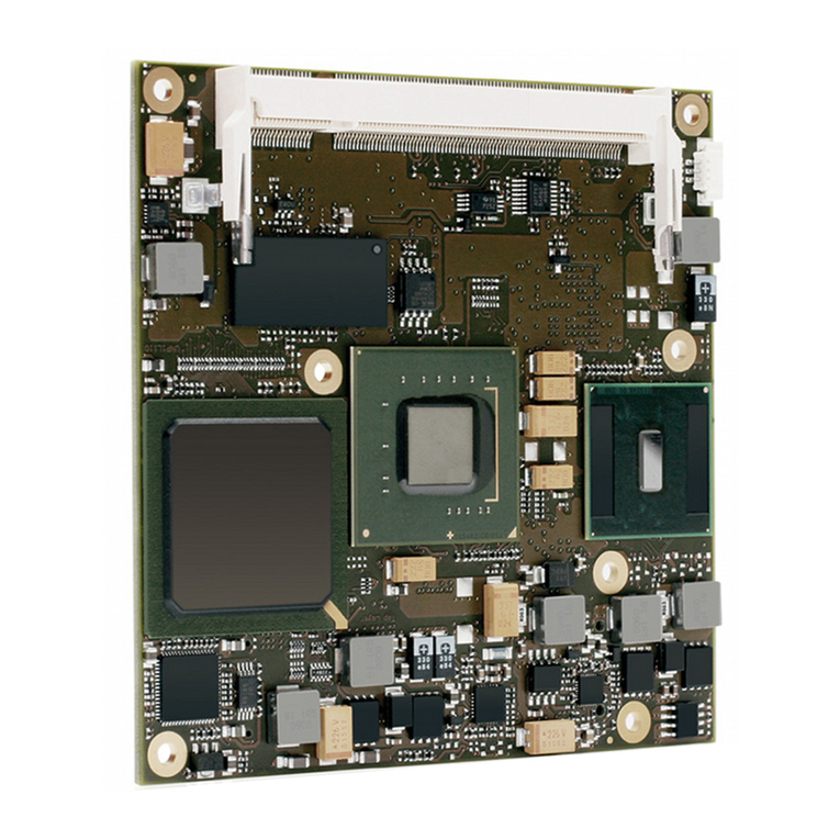
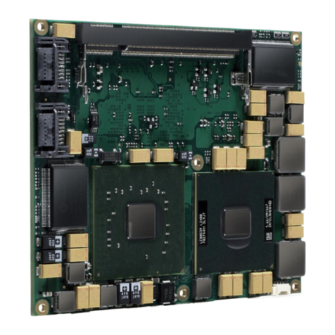
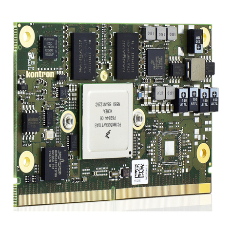
The COMe-bP5020 is a COM Express® form factor compliant Power Architecture® processor module based on the Freescale™
QorIQ™ 64-bit P5020 processor.
Designed in the COM Express® basic (95 mm x 125 mm) form factor the module incorporates the Freescale™ QorIQ™ P5020 dual-
core Power Architecture® processor operating at 2.0 GHz - other processor versions (P5010 and P3041) and operating speeds
are available on request. Featuring 64-bit technology, it integrates up to 8 GByte of soldered DDR3 SDRAM at 1300 MHz and
ECC support. Two additional MBytes of shared third level cache facilitate core-to-core communications to minimize accesses to
main memory.
Up to 2 GB of NAND Flash as well as a socket for a MicroSD card provide flexible and reliable storage space for application data. In
terms of I/Os, the module interfaces the QorIQ-specific I/Os to the carrier board. In addition to USB 2.0 ports there are also UART
(TxD, RxD, RTC and CTS) and Gigabit Ethernet interfaces.
Flexible interface support is guaranteed by 18 SERDES lanes, which can be configured according to application-specific needs.
A comprehensive range of different combinations, for example as PCIe x4, sRIO x4, Serial Gigabit Media Independent Interface
(SGMII), XAUI and SATA interfaces is available.
The COMe-bP5020 with its innovative Data Path Acceleration Architecture (DPAA) assures that even heavy network traffic does
not affect the processing performance of the cores. With DPAA the cores are relieved of the common packet-handling tasks,
which leaves more headroom for the relevant processing even at full load.
The COMe-bP5020 targets high-bandwidth telecommunication and data processing applications. With its long-term availability
of more than 10 years, it is also a very good choice for use in long life cycle network applications in the medical, military and
transportation markets.
www.kontron.com
8
User Guide
COMe-bP5020
1.2 Board Diagrams
Figure 1: COMe-bP5020 Block Diagram
SPI-NOR
FLASH
2x 8 Mb
DDR3 SDRAM
4/8 GB w ECC
18x DDR3 x8
2 banks soldered
FPGA
Board Control
WDog, glue, etc.
COP/
JTAG
Debug
Freescale™
QorIQ™P5020
Dual-Core
64-bit PowerPC
up to 2.2 GHz
DDR3_A
RTC
RGMII
NAND FLASH
up to 2 GB
Ctrl
Sys
EEP
64kb
SPI
COP
Local Bus
I2C_1
SDHC
MicroSD-Card
Socket Uboot Flash
redundant
SPI-NOR
Flash
8 MB
GbE
PHY
Therm.
Sensor
User
EEP
64kb
I2C_2
SPD
EEP
2kb
Bank3 A-D
Eth Ctrl.
SPI-NOR
FLASH
2 MB
OS Boot
ROM/User
DDR3_B
2x Module Connector 0.5 mm pitch 220 pin 4H Receptacle A1-A110/B1-B110/C1-C110/D1-D110
SPI
Bank1 A-D
Bank1 E-H
Bank2 A-D
4x SERDES
4x SERDES
4x SERDES
2x SERDES
MDI
SDHC
1x USB 2.0
USB 1
LAD Bus
4 DIP-SW
I2C#1
I2C#2
RCW
config
eLBC
DC/DC
IN :12V
sRIO x4 or PCIe x4
sRIO x4 or PCIe x4
GbE
4x 1GbE (SGMII)
or 1x 10GbE (XAUI)
USB 2.0
USB
Hub
USB 2
4x USB 2.0
USB Host or Device
4x USB Host
4x RxD/TxD or
2x RxD/TxD/RTS/CTS
1x SD-Card I/F
GPIO
ETH_Mngt 1,2
Local Bus/GPIO
MRAM
512 KB
DUART
2x Serial
SATA 0,1
I2C_4
2x I2C
SPI
SPI
MUX
4x SERDES
Alt.1x 10GbE (XAUI)
I2C#2
I2C#3
MDIO/MDC Eth Mngt
JTAG
JTAG IEEE1588
IEEE1588
IEEE1588
MISC
EXP Card
EXP Card
RCW
EEP
2kb
Bank1 I-J
PCIe x1 or AURORA
MUX
2x SERDES
www.kontron.com
9
User Guide
COMe-bP5020
Figure 2: COMe-bP5020 Board Layout Top View
Figure 3: COMe-bP5020 Board Layout Bottom View
J3
MicroSD
Card
Socket
J4
J2
J1
A1
B1
C1
D1
B110
C110
D110
D7
D6
SW1
www.kontron.com
10
User Guide
COMe-bP5020
1.3 Technical Specifications
Table 1: COMe-bP5020 Main Specifications
COMe-bP5020 SPECIFICATIONS
PROCESSOR
CPU The COMe-bP5020 supports the following microprocessor:
» Freescale™ QorIQ™ P5020 processor, 2.0 GHz
(other operating speeds and processor variants (P5010/P3041) are available on
request)
Further processor features:
» Two 64-bit execution cores
» System Memory interface with optimized support for dual-channel DDR3 SDRAM
memory at 1300 MHz with ECC for the QorIQ™ P5020 processor with 2.0 GHz CPU fre-
quency
Integrated Controllers Controllers integrated in the CPU and utilized by the COMe-bP5020:
» eSDHC, eLBC, DUART, dTSEC, PCIe, sRIO, SPI, I2C
MEMORY
Memory Main memory:
» Up to 8 GB, dual-channel DDR3 SDRAM memory with ECC running at up to 1300 MHz
Cache structure:
» 64 kB L1 cache for each core
» 32 kB instruction cache
» 32 kB data cache
» 512 kB backside L2 cache for each core
» 2 MB shared L3 CoreNet platform cache (1 MB per memory channel)
Flash memory:
» Two SPI boot flashes (2 x 2 MB) for U-Boot selectable via the DIP switch
» One 8 MB SPI flash for operating system or application
Mass storage device:
» Up to 2 GB NAND flash via an integrated/embedded NAND flash controller
» Up to 32 GB microSDHC flash via an integrated SDHC controller
MRAM memory:
» 512 kB of non-volatile memory
Two serial EEPROMs with 64 kbit:
» One for system data storage
» One free for user data storage