2-2
1.
2.
2.
3.
5.
4.
6.
7.
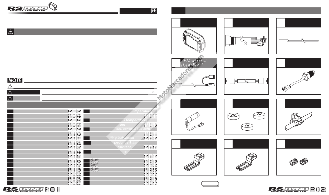
1.M5 X 12L screw X 2
2.Meter bracket for handle bar
3.Fix the bracket on handle bar
(7/8 inch)
4.M5 X 18L screw X 2
5.M5 washer X 2
6.Meter fixed board
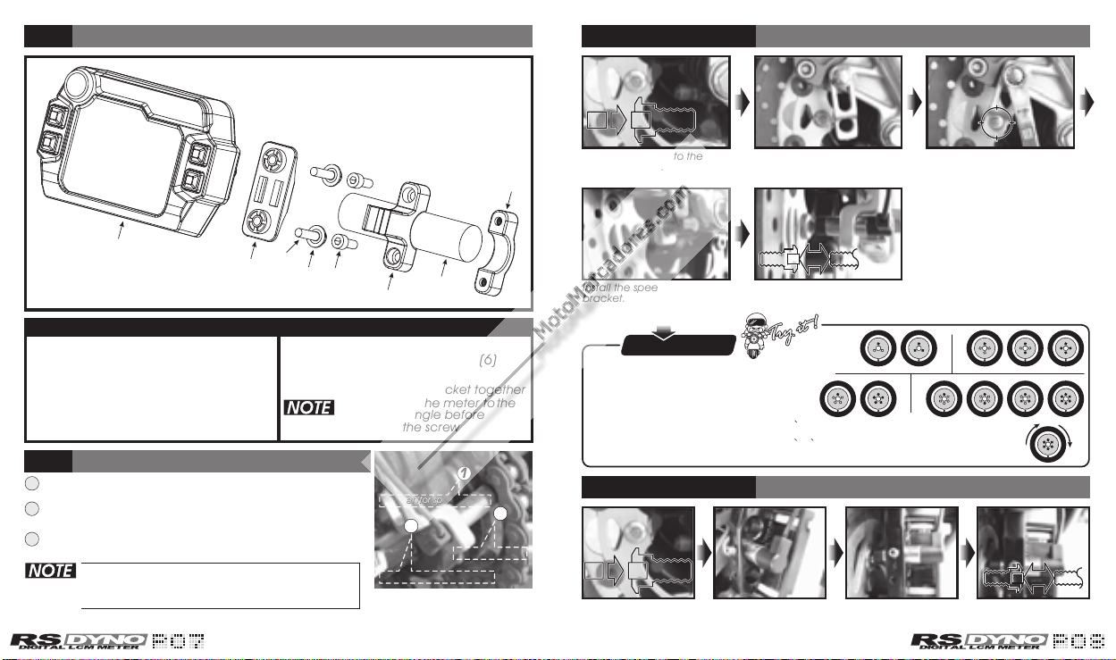
7.Fix the meter on the board (6)
with the screw (5)
8.Fix the meter and thebracket together
Please adjust the meter to the
best visible angle before
tightening the screw
MOTO/SCOOTER
Use the bind & the non-slip
rubber to fix bracket to the
front of the shock and adjust
the proper height and angle.
Speed sensor installation
find a proper hole to put the
sensor in and fix it by
hexagonal bolt.
Please keep the distance
between sensor and magnet
in 8 mm to avoid bad signal.
L type speed sensor bracket instruction
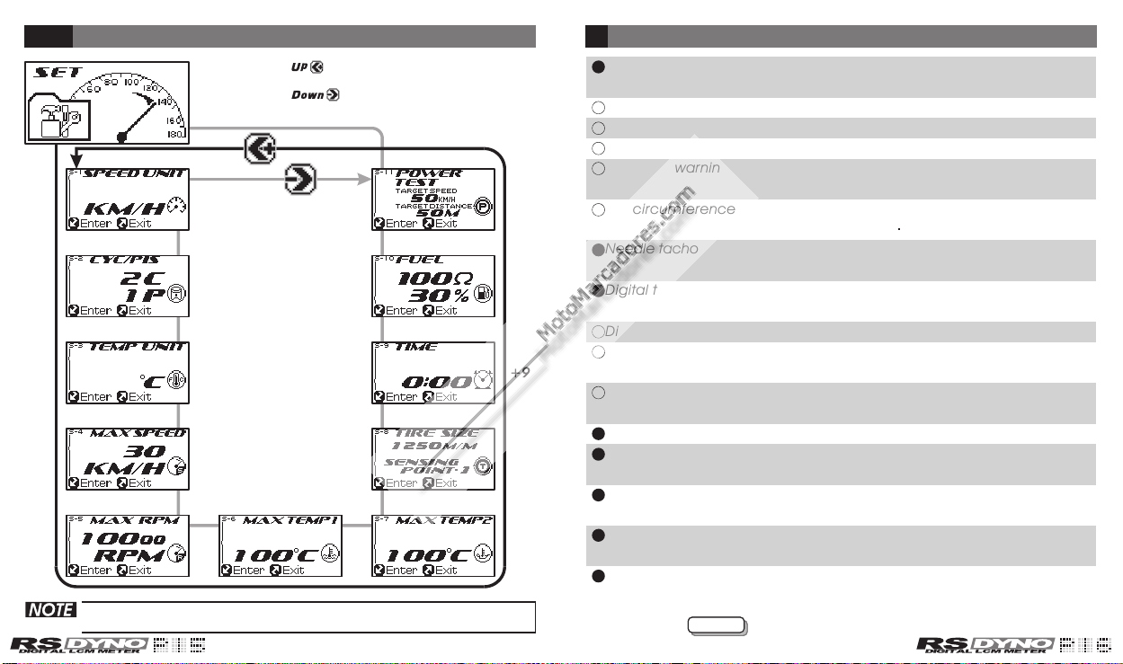
About the setting, please refer to 4-8 tire
size adjustment/ sensor point setting
instruction
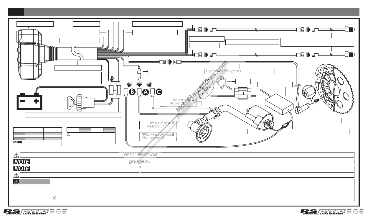
Installation instructions
When installing, please follow the process
1
23
ATV
Magnet (for speed signal)Magnet (for speed signal)
Speed sensorSpeed sensor
S type sensor bracketS type sensor bracket
S type speed sensor bracket instruction
1
2
3
Insert the signal magnet. (Youneed to dig a hole by yourself).
Install the s-type sensor bracket, youcould adjust the proper
distance and angle to fit differentmodel.
After installing the sensor,please adjust the distance between
sensor and magnet . Please keepthe distance in 8 mm.
MOTO/SCOOTER
SPEED
SENSOR
SPEED
SENSOR
MAGNETMAGNET BELOW
mm8
BELOW
8mm
S type speed sensor bracket instruction
P.S.P.S.
The more magnet sensor points are,the less the display
interval is. When installing the magnet, please put the
magnet with N-mark side face the outside and put
them averagely to avoid wrong signal.
EX. 1: If your disk has 3 screws, you could install 1 or 3
magnets to catch the speed.
EX. 2: If your disk has 4 screws, you could install 1 2 or 4 magnets to catch the speed.
EX. 3: If your disk has 5 screws, you could install 1 or 5 magnetsto catch the speed.
EX. 4: If your disk has 6 screws, you could install 1 2 3 or 6 magnets to catch the speed.
After finishing the magnet installation and sensor point setting, please move your tire to
test the speedometer work or not.
EX. 1 EX. 2
EX. 3 EX. 4
Put the magnet into the brake
disc screw hole.
Install the s type sensor
bracket.
Install the speed sensor on the
bracket.
Adjust the sensor bracket position
to make sure that thesensor
could face the magnet to prevent
bad speed signal or no signal!
Adjust the distance between sensor andmagnet.
We suggest you to makesure the distance is under
8mm for catching good speed signal.
Put the magnet into the
brake disc screw hole.
SPEED
SENSOR
SPEED
SENSOR
MAGNETMAGNET BELOW
mm8
BELOW
8mm
Cortesia de www.motomarcadores.com
Cortesia de www.motomarcadores.com