KRAMER: SIMPLE CREATIVE TECHNOLOGY
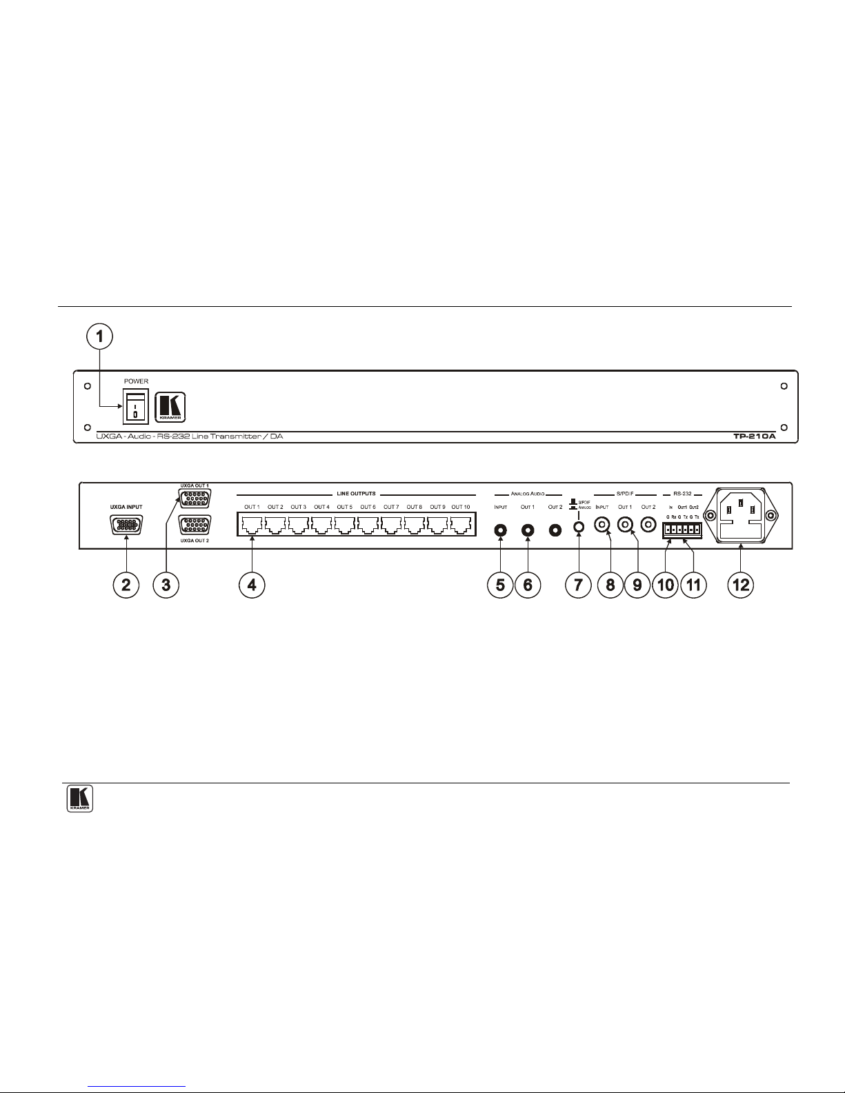
Connecting the TP-210A
8
6 Connecting the TP-210A
This section describes how to connect the TP-210A (see section 6 ), wire the
CAT 5 LINE OUT RJ-45 Connectors (see section 6.1), and wire the RS-232
connectors (see section 6.1).
To connect the TP-210A, as illustrated in Figure 3, do the following1:
1. Connect a UXGA source (for example, a laptop’s graphics card) to the
UXGA INPUT 15-pin HD connector.
2. Connect an analog2audio source to the Audio IN 3.5mm mini jack, for
example, using a Kramer C-GMA/GMA cable (VGA 15-pin HD +Audio
jack to VGA 15-pin HD +Audio jack)3, and press the S/PDIF – ANALOG
selector button.
3. Connect an RS-232 cable with a 9-pin D-sub connector at one end to the
laptop, and a 2-pin terminal block connector at the other end to the RS-232
IN port (G, Rx).
4. Connect the UXGA OUT 1 15-pin HD connector to the UXGA acceptor
(for example, a plasma display), and the ANALOG AUDIO2OUT 1
3.5mm mini jack connector to the analog audio connector on the acceptor. If
required, connect the RS-232 G and TX1 terminal block connector to the
RS-232 port on the acceptor.
5. Connect the UXGA OUT 2 15-pin HD connector to a UXGA acceptor (for
example, a display), and the ANALOG AUDIO2OUT 2 3.5mm mini jack
connector to the analog audio acceptor (for example, an AV Receiver).
6. Connect the LINE OUTPUT CAT 5 connectors as follows4:
The LINE OUT 1 RJ-45 connector on the TP-210A to the LINE IN
RJ-45 connector on a TP-1245unit via UTP cabling6(with a range
of up to 300ft (up to 100m))7
The LINE OUT 10 RJ-45 connector on the TP-210A to the LINE
IN RJ-45 connector on another TP-124,via UTP cabling (with a
range of up to 300ft (up to 100m))
1 Switch OFF the power on each device before connecting it to your TP-210A. After connecting your TP-210A, switch on its
power and then switch on the power on each device
2 Alternatively, you can connect a digital audio source and acceptors and release the S/PDIF – ANALOG selector button
3 Not supplied. The full list of Kramer cables is on our Web site at http://www.kramerelectronics.com. You can also connect
a UXGA source to the UXGA IN 15-pin HD connector, and a separate audio source to the AUDIO IN 3.5mm mini jack
4 You do not have to connect all the outputs
5 Refer to the separate user manual, which can be downloaded at http://www.kramerelectronics.com
6 For details of how to wire a CAT 5 LINE IN/LINE OUT RJ-45 connector, see section 6.1
7 Alternatively, you can connect the Kramer TP-46, which can be connected to an additional TP-46 unit for transmitting the
signal further