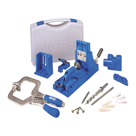
Kreg FOREMAN DB210 User manual

FOREMAN
DB210
OWNER’S MANUAL
GUIDE D’UTILISATION
MANUAL DEL PROPIETARIO
www.kregtool.com • 800.447.8638
NK9348
Version 3 - 10/2018
DB210

Safety
!
!
!
WARNING This product contains one or more chemicals known
to the State of California to cause cancer and birth defects or other
reproductive harm. Wash hands after handling.
General Safety Rules
WARNING For your own safety, read the owner’s manual before
operating this pocket-hole machine.
WARNING Read all instructions. Failure to follow all instructions
listed below may result in electric shock, re and/or serious injury.
The term "power tool" in all of the warnings listed below refers to
your mains-operated (corded) power tool or battery-operated
(cordless) power tool.
SAVE THESE INSTRUCTIONS
1) Work area safety
a) Keep work area clean and well lit. Cluttered or dark areas invite
accidents.
b) Don’t use power tools in a dangerous environment. Don’t use
power tools in damp or wet locations, or expose them to rain.
c) Do not operate power tools in explosive atmospheres, such as
inthepresenceofammableliquids,gasesordust. Power tools
create sparks which may ignite the fumes or dust.
d) Keepchildrenandbystandersawaywhileoperatingapower
tool. Distractions can cause you to lose control.
e) Make your workshop child proof with padlocks, master switches,
or by removing starter keys.
2) Electrical safety
a) Do not expose power tools to rain or wet conditions. Water
entering a power tool will increase the risk of electric shock.
b) Donotabusethecord.Neverusethecordforcarrying,
pulling or unplugging the power tool. Keep cord away from heat,
oil, sharp edges or moving parts. Damaged or entangled cords
increase the risk of electric shock.
c) Use a proper extension cord and make sure it is in good
condition. When using an extension cord, be sure to use one heavy
enough to carry the current your machine draws. An undersized cord
causes a drop in line voltage resulting in loss of power and
overheating. Table1 on the following page shows the correct cord
gauge to use depending on cord length and nameplate ampere
rating. If in doubt, use the next heavier gage. The smaller the gage
number, the heavier the cord.
3) Personal safety
a) Stay alert, watch what you are doing and use common sense
when operating a power tool. Do not use a power tool while
youaretiredorundertheinuenceofdrugs,alcoholormedication.
A moment of inattention while operating power tools may result in
serious personal injury.
b) Always wear safety glasses. Everyday eyeglasses only have
impact resistant lenses, they are NOT safety glasses.
c) Usesafetyequipment. Use a face or dust mask when the cutting
operation is dusty. Safety equipment such as a dust mask, non-
skid safety shoes, hard hat, or hearing protection used for appropriate
conditions reduces personal injuries.
d) Avoid accidental starting. Make sure the switch is in the off-
positionbeforepluggingin. Carrying power tools with your nger
on the switch or plugging in power tools that have the switch on
invites accidents.
e) Removeanyadjustingkeyorwrenchbeforeturningthepower
tool on. A wrench or a key left attached to a rotating part of the power
tool may result in personal injury.
f) Donotoverreach.Keepproperfootingandbalanceatall
times. This enables better control of the power tool in unexpected
situations.
g) Secure workpieces. Use clamps or a vise to hold work when
practical. This is safer than using your hand and it frees both hands to
operate the tool.
h) Never stand on the machine. Serious injury could occur if the tool
tips or if the cutting tool is unintentionally contacted.
i) Dress properly. Do not wear loose clothing or jewelry. Keep
your hair, clothing and gloves away from moving parts. Loose
clothes, jewelry or long hair can be caught in moving parts.
j) If devices are provided for the connection of dust extraction
and collection facilities, ensure these are connected and
properly used. Use of these devices can reduce dust-related hazards.
4) Power tool use and care
a) Keep guards in place and in working order.
b) Do not force the power tool. Use the correct power tool for
your application. The correct power tool will do the job better and
safer at the rate for which it was designed.
c) Use right tool. Don’t force tool or attachment to do a job for which
it was not designed.
d) Do not use the power tool if the switch does not turn it on
and off. Any power tool that cannot be controlled with the switch is
dangerous and must be repaired.
e) Disconnecttheplugfromthepowersourceand/orthebattery
packfromthepowertoolbeforemakinganyadjustments,
changing accessories, or storing power tools. Such preventive
safety measures reduce the risk of starting the power tool accidentally.
f) Never leave tool running unattended. Turn power off. Don’t
leave tool until it comes to a complete stop.
g) Store idle power tools out of the reach of children and do
not allow persons unfamiliar with the power tool or these
instructions to operate the power tool. Power tools are dangerous
in the hands of untrained users.
h) Maintainpowertools.Checkformisalignmentorbindingof
movingparts,breakageofpartsandanyotherconditionthat
may affect power tool operation. If damaged, have the power
toolrepairedbeforeuse. Many accidents are caused by poorly
maintained power tools.
i) Keep cutting tools sharp and clean. Properly maintained cutting
tools with sharp cutting edges are less likely to bind and are easier to
control.
j) Use the recommended speed for the cutting tool or accessory
and workpiece material.
k) Onlyusepartsandaccessoriesrecommendedbythe
manufacturer. Consult the owner’s manual for recommended
accessories. Using improper accessories may cause personal injury.
l) Usethepowertool,accessoriesandtoolbitsetc.,in
accordance with these instructions and in the manner intended
for the particular type of power tool, taking into account the
workingconditionsandtheworktobeperformed. Use of the
power tool for operations different from those intended could result in
a hazardous situation.
5) Service
a) Haveyourpowertoolservicedbyaqualiedrepairperson
using only identical replacement parts. This ensures that the
safety of the power tool is maintained.

Safety
6) AdditionalSafetyRulesfortheDB210Foreman
a) Toreducetheriskofelectricshock,thisequipmenthasa
polarizedplug(onebladeiswiderthantheother).Thisplug
tsinapolarizedoutletonlyoneway. If the plug does not t fully
in the outlet, rotate the plug. If it still does not t, contact a qualied
electrician to install the proper outlet. Do not change the plug in any way.
b) Handle the drill guides with care and keep hands away when
they are installed in the machine. The minimal clearance required
between the drill bit and the drill guide to enhance hole quality
produces a sharp edge that may present a laceration hazard.
c) Keephandsawayfromtherotatingbitand
workpiece clamp when operating the machine.
d) Makesurethebitiscompletelywithdrawnfromtheworkpiece
andcomestoacompletestopbeforeadjustingtheworkpieceposition.
e) Secure the machine to prevent tipping or sliding.
Never stand on the machine.
f) Followalllubricationandmaintenance
practices detailed in the instruction manual.
g) Thismachineisdesignedforaspecicapplication.Donot
modify and/or use it for any other application. If you have questions
relative to the application of the machine, DO NOT use it until you
have contacted Kreg Tool Company and have been advised accordingly.
7) Thelabelonyourmachinemayincludethesymbolsbelow. The
symbols and their denitions are as follows:
safetyalertsymbol
volts
hertz
amperes
watts
direct current
alternating current
alternating or direct current
ClassIConstruction(grounded)
ClassIIConstruction(doubleinsulated)
earthing terminal
minutes
per minute
beatsperminute
revolutions per minute
no load speed
V
Hz
A
W
min
/min
BPM
RPM
!
English
3
• Be sure that the cutter knives are mounted as described in the
instruction manual and check that all bolts are firmly tightened
before connecting unit to power source.
• To avoid injury, never rotate the cutter block directly with your
hands.
• Keep guards in place and in good working order.
• Stay alert – never operate the unit when tired or under the
influence of drugs, alcohol, or medication.
• Do not use in dangerous environments. Do not use near
flammable substances, in damp or wet locations, or expose to
rain.
• Never plane material which is shorter than 12 inches.
• Exhaust chute: remove shavings with brush or vacuum after
power has been shut off and cutter head has stopped rotating.
• ALWAYS LOCATE PLANER WITH PROPER CLEARANCE ON
THE OUTFEED SIDE of the unit to prevent pinching or binding of
the workpiece against any obstacle.
• Clean out your tool often, especially after heavy use. Dust
and grit containing metal particles often accumulate on interior
surfaces and could create a risk of serious injury, electric shock or
electrocution. ALWAYS WEAR SAFETY GLASSES.
WARNING: For your own safety, it is recommended that two
people carry this machine or serious injury could result.
WARNING: Always wear proper personal hearing protection
that conforms to ANSI S12.6 (S3.19) during use. Under some
conditions and duration of use, noise from this product may
contribute to hearing loss.
WARNING: Some dust created by power sanding, sawing,
grinding, drilling, and other construction activities contains chemicals
known to the State of California to cause cancer, birth defects or
other reproductive harm. Some examples of these chemicals are:
• lead from lead-based paints,
• crystalline silica from bricks and cement and other masonry
products, and
• arsenic and chromium from chemically-treated lumber.
Your risk from these exposures varies, depending on how often you
do this type of work. To reduce your exposure to these chemicals:
work in a well ventilated area, and work with approved safety
equipment, such as those dust masks that are specially designed to
filter out microscopic particles.
• Avoid prolonged contact with dust from power sanding,
sawing, grinding, drilling, and other construction activities.
Wear protective clothing and wash exposed areas with
soap and water. Allowing dust to get into your mouth, eyes, or
lay on the skin may promote absorption of harmful chemicals.
WARNING: A dust mask or respirator should be worn by all
persons entering the work area. The filter should be replaced daily or
whenever the wearer has difficulty breathing. See your local hardware
store for the proper NIOSH/OSHA approved dust mask.
• The label on your tool may include the following symbols. The
symbols and their definitions are as follows:
V......... volts A .......amperes
Hz....... hertz W ......watts
min ..... minutes .....alternating current
... direct current .....alternating or direct current
....... Class I Construction no......no load speed
........... (grounded) ......earthing terminal
....... Class II Construction .....safety alert symbol
........... (double insulated) BPM..beats per minute
…/min per minute RPM..revolutions per minute
ForemanDB210motorspecications
120 V~5.0A 2,800 rpm
Guidelines for extension cord use
Extension cords are only to be used for temporary purposes. They do
not replace the need for installation of outlets and proper wiring where
necessary.
In the shop and on construction sites:
1. Extension cords with an equipment grounding conductor must be used at
all times.
2. Extension cords must be protected from damage, and not run through
doorways or windows where the doors or windows may close, causing
damage to the cord.
3. Extension cords should be a minimum of 16 AWG and be rated for the
equipment in use.
4. Extension cords must be periodically inspected to ensure that the
insulation and conductivity of the wires are not compromised.
5. Extension cords should not be run through water or allowed to have
connections that may be exposed to accumulated water.
Extension cord
gauge
Extension Cord Length
Nameplate Amperes
@120 V
25’ 50’ 75' 100' 150' 200'
0 -5 16 16 16 14 12 12
5.1 - 8 16 16 14 12 10 NR
8.1 -12 14 14 12 10 NR NR
12.1 - 16 12 12 NR NR NR NR
NR – Not Recommended
TABLE1
WARNING:
!
This product can expose you to chemicals including lead, which
is known to the State of California to cause cancer, birth defects or reproductive
harm. For more information go to www.P65Warnings.ca.gov.
WARNING:
!
This product can expose you to chemicals including lead and
other chemicals, which are known to the State of California to cause cancer, birth
defects or reproductive harm. For more information go to
www.P65Warnings.ca.gov/wood.
WARNING:
!
Drilling, sawing, sanding or machining wood products can
expose you to wood dust, a substance known to the State of California to cause
cancer. Avoid inhaling wood dust or use a dust mask or other safeguards for
personal protection. For more information go to www.P65Warnings.ca.gov/wood.
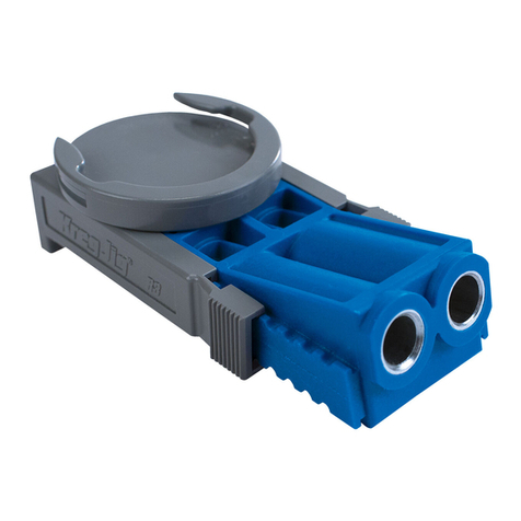
Introduction
Item# Description
Parts
1
8
7
6
5
4
3
2
9
10
11
12
13
14
15
16
17
Control arm
Arm lock
Machine base
Handles
Vacuum port
Self-tapping screws
Vacuum shroud
Truss-head machine screws
Hose clamps
Vacuum hose
Access panel
Machine top
3mm hex wrench
Cover levelers
¼-turn fence-lock handles
Fence
Fence-lock screws
Fence-lock bases
Workpiece thickness marks
Drill bit
Drilling-depth stop knob
Drilling-depth setting block
Drill guide (Standard guide included)
Depth-stop jam nut
Clamp-arm housing
Clamp pad
Clamp adjustment knob
Clamp jam nut
Clamp arm
Switch lock-out button
Switch
Workpiece stops
Center-reading measuring tape
#2 square driver bit 6” long
Accessory tray
Foot
Mounting hole
Panel support
Link-release pin
Motor
Guide rods
Quick-change chuck
Motor link
Hinge pivots
Pivot sockets
Drill guide set screw
18
Item# Description
20
19
28
31
38
37
36
35
34
33
32
39
21
22
23
24
25
26
27
29
Congratulations on choosing a Kreg Foreman DB210 semi-automatic pocket-hole machine. Please read all instructions and safety
information contained in this manual before using this product.
Owning a Foreman gives you all the advantages of a true production pocket-hole machine with the compactness and portability of a
bench-top tool. This manual guides you through the steps necessary to adjust your machine and drill pocket holes. In addition to this
manual, you may nd the following resources helpful:
30
40
41
42
43
44
45
Kreg Online: To order more pocket-hole screws, view accessories available for your jig, or get help making a particular joint,
go to kregtool.com.
Kreg Owner’s Community: Sign up as a member, create your own page, view other members’ projects, post photos of your
projects, view how-to videos, and participate in forums by going to kregjig.ning.com.
Kreg YouTube Channel: For project, product, and tip videos, visit youtube.com/user/kregtoolcompany.
Kreg on Facebook: Connect with Kreg on Facebook to share your projects and get inspiration from our fans and friends at
facebook.com/kregJig.
46

Parts
10
6
5
7
4
32
32
36
37
11
4
15
25
31
30
1
33
16
15
29
28
27
922
34
13
8
12
26
23
21
17
17
3

Parts
4
2
24
15
21
25
15
19
3
40
4
35
39
38
14
43
46
14
23
41
20

Assembly
Push down on the control arm (1), release the arm lock (2) at the
back of the machine base (3), and guide the control arm to the full-
up position. Do not let the arm snap into the full-upright position.
For transportation and storage, push down on the control arm and
engage the arm lock.
Release the control arm
The Foreman is supplied with a chip-removal system that includes a
11⁄4" vacuum port (5) and self-tapping screws (6), vacuum shroud (7)
and machine screws (8), hose clamps (9), and vacuum hose (10). In
addition to helping keep your work area clean, ecient chip removal
speeds drilling time and reduces heat build-up, extending the life of
your drill bit. A Foreman with the chip-removal system installed must
be connected to a shop vacuum when in use. Not connecting the
chip-collection system to a shop vacuum causes chips to collect in
the hose and vacuum shroud and eventually clog the drill bit. The
Foreman can be used without the chip-collection system in place.
If you install the system and nd that you must use your Foreman
without a shop vacuum, simply disconnect the vacuum hose from the
vacuum shroud.
To install the chip-removal system, turn the Foreman onto one side
and from the inside of the machine base (3), insert the vacuum port
(5) into the hole in the back of the base and secure it from the outside
with two self-tapping screws (6). Fasten the vacuum shroud (7) to the
machine with four truss-head machine screws (8).
Slip the hose clamps (9) over the ends of the vacuum hose (10) and
slip the vacuum hose ends onto the vacuum port and vacuum shroud.
To make it easy to disconnect the vacuum hose from the vacuum
shroud when working through the access panel (11), orient the front
hose clamp with the screw head facing the front of the machine.
Tighten the clamps and turn the Foreman upright.
Install the chip-removal system
9
8
7
6
10
5
7
9
Always disconnect the machine from power before assembly,
opening the access cover, or making any adjustments.
Never lift or carry the machine by the control arm. Always use the
handles (4) at the front and rear of the machine.
The access panel should be ush with the machine top right out of
the box. Should it need adjustment, use the following procedure:
Place the machine on saw horses so you have access to the bottom
of the machine. Lay a straight edge across the machine top (12) and
access panel (11). Use the 3mm hex wrench (13) supplied with the
machine to turn the cover levelers (14).
Level the access panel
11
12
Engage
Release
2
14
13
4
14
WARNING:
!
Handle the drill guides with care and keep hands away when they are installed in
the machine. The minimal clearance required between the drill bit and the drill guide to enhance hole
quality produces a sharp edge that may present a laceration hazard.

Assembly
Rotate the ¼-turn fence-lock handles (15) clockwise (locked position).
If the fence (16) can be moved with moderate pressure, tighten
the fence-lock screws (17). Rotate the handles counterclockwise
(unlocked position) and verify that the fence moves freely.
Should it ever be necessary to disassemble the fence locks, the
fence-lock bases (18) must be oriented with the at area indicated in
the drawing facing the fence.
Adjust the fence-lock pressure
16
17
For a strong joint, the pocket screw should exit at the center of the
workpiece thickness. This is accomplished by adjusting the fence
position.
Unlock the fence (16) by rotating the fence-lock handles (15)
counterclockwise. Align the rear edge of the fence with the workpiece
thickness marks (19) cast into the machine top (12) that correspond
to your workpiece thickness. Rotate the handles clockwise to lock the
fence in place.
(1) Position the Fence for Workpiece Thickness
To create strong joints, you’ll adjust machine settings to match
the thickness of the workpiece and the length of the screw. The
Foreman makes this easy, in just four simple steps:
Screw Length Selection Guide
Material Thickness Screw Length
1⁄2" [13 mm]* 1" [25 mm]**
5⁄8" [16 mm] 1" [25 mm]
3⁄4" [19 mm] 11⁄4" [32 mm]
7⁄8" [22 mm] 11⁄2" [38 mm]
1" [25 mm] 11⁄2" [38 mm]
11⁄8" [29 mm] 11⁄2" [38 mm]
11⁄4" [32 mm] 2" [51 mm]
13⁄8" [35 mm] 2" [51 mm]
11⁄2" [38 mm] 21⁄2" [64 mm]
Kreg oers a complete line of pocket screws for every workpiece
thickness and type. Use this guide to select the correct screw
length. All Kreg pocket screws are available at your Kreg dealer or
online at www.kregjig.com.
(2) Choose a screw
12
19 16 15
15
Operation
Fine Thread
Because the smaller diameter and thread pitch of our #7 ne-thread screws reduce
the chance of splitting the material, we recommend them for hardwoods.
Coarse Thread
Due to the large diameter and thread pitch, our #8 coarse-thread screws offer a
strong hold in softwoods and composite materials such as plywood, particleboard,
and MDF.
18
at area
Note: Screw length is measured from bottom of the head to
the tip of the screw.
11⁄4" (32mm)
*Panhead pocket screw recommended. When using optional Micro-Pocket™Drill
Guide, 3⁄4" screws are recommended for
1⁄2" material. See Micro Owner's manual.

Operation
Pull the control arm (1) down, advancing the drill bit (20) until the tip
touches the fence (16). If necessary, turn the drilling-depth stop knob
(21) counterclockwise. Return the control arm to the full-up position,
retracting the bit.
Place the drilling-depth setting block (22) against the fence with the
screw-length marks facing up. Center the block step that corresponds
to the length of screw you’ll be using on the drill guide (23). Pull down
on the control arm, inserting the drill-bit pilot tip into the hole in the
step. With the drill-bit shoulder against the block step, turn the drilling-
depth stop knob (21) clockwise until it stops. Tighten the depth-stop
jam nut (24) against the base of the clamp-arm housing (25). Return
the control arm to the full-up position.
Note: When re-locking the control arm for transportation or
storage, turn the depth-stop knob counterclockwise to allow the
arm to return to the full-down position.
(3) Set the drilling depth
20
16
21
1
25
22
24
Using the Drilling-Depth Setting Block
Drill Guide & Bit Material Thickness Screw Length Setting Block Step
Micro* ½" ¾" ¾"
Micro* & Standard ⅝" – 1⅛" 1", 1¼", 1½" 1", 1¼", 1½"
Standard 1¼" – 1⅜" 2" 2"
Standard & HD* 1½" 2½" 2½"
*optional accessories
When using the chip-collection system, connect a shop vacuum
to the vacuum port (5) and turn it on. Hold the workpiece securely
against the fence (16) with the pocket-hole location centered on
the drill guide (23). Depress the switch lock-out button (30) on the
control arm (1) and pull the switch (31), turning on the drill motor.
Let the motor reach full speed and pull the control arm down in
a smooth motion until the depth stop makes contact. Return the
control arm to the full-up position and release the switch.
Drilling pocket holes
Raise the control arm (1) to the full-up position. Place the workpiece
against the fence (16) and under the clamp pad (26). Turn the clamp
adjustment knob (27) clockwise until the clamp pad contacts the
workpiece. Now turn the knob counterclockwise one-half turn. Tighten
the clamp jam nut (28) against the clamp arm (29). The clamp is now
positioned so lowering the control arm applies sucient pressure to
secure the workpiece before the drill bit enters the wood.
(4) Adjust the workpiece clamp
16
1
27
28
26
29
WARNING:
!
Handle the drill guides with care and keep hands away when they are installed in
the machine. The minimal clearance required between the drill bit and the drill guide to enhance hole
quality produces a sharp edge that may present a laceration hazard.

Operation
In addition to the proper machine settings, proper spacing of pocket
holes in the workpiece is important for making a strong joint. For
narrow parts such as rails, stiles and frames, locate pocket holes ⅜" to
½" from each edge. Shaded lines on the measuring tape indicate this
oset, eliminating the need to mark pocket-hole locations. Simply align
the edge of your workpiece with the shaded line and drill. For wide
parts such as panels and table tops, place the rst pocket hole 2" from
the edge and every 6" on center after that.
Pocket-hole placement
A workpiece stop can be used on either side of the drill guide by
sliding it out of the fence T-slot, ipping it over so the open end
of the stop arm faces center, and reinstalling it in the T-slot.
Loosen the socket-head bolt on the workpiece stop (32) with the
3mm hex wrench (13), slide the stop to the desired location, and
tighten the bolt. Keeping the fence (16) centered side to side allows
you to use the center-reading measuring tape (33) to position the
stops. Override a stop by placing the workpiece over the stop,
pressing the spring-loaded stop arm into the stop body.
Each stop arm can be held in the retracted position by pressing
the arm into the stop body and then sliding it toward the socket-
head bolt that secures the stop in the fence. The notch in the arm
provides a grip point. To reactivate the stop arm, slide it away from
the bolt.
Workpiece stops
16 13
33
32

Operation
To prevent unauthorized use of the machine, a hole through the
switch (31) allows it to be locked in the o position with a padlock
(not included).
Switch lock-out
You can store the hex wrench (13), #2 square driver bit (34), and
optional Micro and HD drill guides and bits in the accessory tray (35)
located under the access panel (11).
Accessory storage
For exibility in securing your Foreman to a work surface, the foot
(36) at each corner of the machine base features a at surface
for temporarily clamping the machine to a work bench as well as
a mounting hole (37) for more permanent attachment. (The holes
accept #14 x 21⁄2" Kreg HD pocket-hole screws.)
Secure mounting
36
37
31
35

Operation
1. Keep the motor clean and the machine base free of wood chips
and dust. When used without a shop vacuum, routinely remove
waste material from inside the cabinet or mount the machine on
an open stand that prevents waste-material accumulation.
2. Periodically lubricate the guide rods with a dry-lm lubricant
such as Dri-Tool™ Lubricant from Empire Manufacturing. A dry
lm lubricant will not collect wood chips and dust and will extend
the life of the bearings and the guide rods. The motor link and
linkage associated with the clamping mechanism should be
lubricated periodically to ensure free movement.
3. Use a sharp drill bit. You can drill between 4,000 and 5,000
holes in oak before sharpening the bit. Adjust your sharpening
schedule for your settings and the material that you are
drilling. Keeping the drill bit clean and free of pitch, resin,
and glue signicantly extends the life of the bit. Periodically
clean the drill bit with a cleaner such as Blade Saver™ and
apply a dry lubricant such as OptiCut-XL™, both from Empire
Manufacturing. Even a dirty drill bit can be very sharp, so
exercise caution when handling the cutting edges.
Kreg oers a sharpening service for Standard pocket-hole
drill bits only. Call or e-mail customer service at 800.447.8638 /
Use the appropriate procedure below when replacing a drill bit
or installing the optional Micro or HD drill bits and drill guides.
To protect the workpiece stops (32) when opening the access
panel (11), release the fence-lock handles (15) and move the
fence (16) all the way back. Turn the clamp adjustment knob (27)
counterclockwise to raise the clamp pad (26). Open the access
panel and engage the panel support (38). Remove the link-release
pin (39) and slide the motor (40) o the guide rods (41).
To replace the drill bit (20), pull the quick-change chuck (42) collar
forward and remove the drill bit. Insert the new drill bit hex shank
into chuck, and release the collar. Slide the motor onto the guide
rods, inserting the drill bit into the drill guide (23). Align the motor
link (43) with the link hole on the motor, and insert the link-release
pin. Disengage the access panel support and close the panel.
When switching to the optional Micro or HD drill and guide, change
the drill bit as instructed above. Then disconnect the vacuum hose
(10) from the vacuum shroud (7). Lift the access panel o the
machine, disengaging the hinge pivots (44) on the access panel
from the pivot sockets (45) on the machine top (12).
Place the access panel upside down on a at surface (for example,
a tablesaw table). Loosen the drill-guide set screw (46) with the
3mm hex wrench (13) and remove the drill guide. Firmly holding the
access cover against the at surface, slide the new drill guide into
the opening, rotate it so the angled face is against the at surface,
and tighten the set screw.
Install the access panel on the machine and engage the panel
support. Reconnect the vacuum hose to the vacuum shroud. Slide
the motor onto the guide rods, inserting the drill bit into the drill
guide. Connect the motor link (43) to the motor with the link-release
pin and close the cover.
Replacing a drill bit or installing a drill bit and
drill-guide set
41
45
11
46
12
13
44
42
40
41
20
41
44
Maintenance
23
WARNING:
!
Handle the drill guides with care and keep hands away when they are installed in
the machine. The minimal clearance required between the drill bit and the drill guide to enhance hole
quality produces a sharp edge that may present a laceration hazard.

Two pocket holes with our recommended 9⁄16" center-to center spacing
t entirely on the face of 3⁄4"-thick boards at least 23⁄8" wide. Simply set
up the machine for 3⁄4"-thick stock. Then with the mitered end of the
workpiece against the fence, drill one hole 7⁄16" from the miter heel and
a second hole 25⁄16" from the miter toe.
You also can drill one pocket hole on each side of a miter joint rather
than drilling both holes on the same side.
Mitered corners
1⁄2"
2 5⁄16"
Maintenance
To ensure product safety and reliability, all motor repairs should be performed by the Kreg Tool Company factory service center.
Call Kreg Customer Service (800.447.8638) for return authorization and shipping instructions.
Motor service
For a diagram and list of replacement parts and assemblies, go to www.kregtool.com and view the online version of this manual.
Replacement parts
1. Test Pieces
Test the joint with scrap pieces cut from the same stock as
your nal workpiece.
2. Make sure you’re using Kreg Screws
Kreg screws feature sharp, self-tapping tips that slice through
the wood bers instead of forcing them apart.
3. Use the Right Screw Type
Use ne-thread screws in hardwood. These #7 screws
displace less wood than the #8 coarse-thread screws used
for softwood, plywood, MDF, and particleboard.
4. Screw it In, Back it Out
Drive the screw half-way in, back it out to clear excess wood
bers from the hole, and then drive the screw all the way in.
5. Reduce Friction
Apply bee’s wax or other lubricant to the screw to reduce the
friction as the screw enters the workpiece.
6. Clamp Correctly
Center the pads of your Kreg Face Clamp™ on the
joint line with the large clamp pad on the face opposite
the pocket holes. Adjust the clamp to apply enough
pressure to keep the workpieces ush and stable but not
so tight to make clamping dicult.
6 Tips to reduce splitting
Tips

Tips
Kreg Face Clamps™
ITEM# KHC-PREMIUM (3" reach),
ITEM# KHC-LARGE (6" reach),
ITEM# KHC-XLARGE (10" reach)
With a choice of 3"-, 6"-, and 10" reach, there’s a Kreg Face Clamp™
that meets your needs.
Common Board Sizes
Nominal Size Actual Size
1x2 3⁄4" x 11⁄2"
1x3 3⁄4" x 21⁄2"
1x4 3⁄4" x 31⁄2"
1x6 3⁄4" x 51⁄2"
1x8 3⁄4" x 71⁄4"
2x2 11⁄2" x 11⁄2"
2x4 11⁄2" x 31⁄2"
2x6 11⁄2" x 51⁄2"
2x8 11⁄2" x 71⁄4"
4x4 31⁄2" x 31⁄2"
6x6 51⁄2" x 51⁄2"
At a lumber yard or home center you’ll see labels on lumber such as
“1x6” and “2x4.” These “nominal” sizes once described the dimensions
of rough-cut lumber before it was milled to nished or actual size.
Actual size is always less than nominal size.
The board-thickness marks on your Kreg Jig refer the actual thickness
of the board. For example, a 1x4 is actually 3⁄4" thick, so you’ll set your
jig to the 3⁄4" mark.
Nominal size vs. actual size
HD Drill Bit
ITEM# DB210-HDB
Replacement drill bit for the DB210 Foreman G2
Kreg Jig®HD Drill Guide and Drill Bit
ITEM# DB210-HDBB
Designed for use with “2-by” material, this heavy-duty system drill holes
for #14 x 21⁄2" pocket screws.
Available from your Kreg dealer or online at www.kregtool.com.
Micro Pocket™ Drill Guide and Drill Bit
ITEM# DB210-MBB
With a hole diameter 25% smaller than our standard pocket hole, the
Micro Pocket™ Drill Guide lets you create compact pocket holes in thin
stock, and tight repair applications.
Optional Accessories
4"
31⁄2"
11⁄2"
2"
Nominal
(2" x 4")
Actual
(11⁄2" x 31⁄2")

Foreman DB210 Semi-Automatic Pocket Hole Machine
Kreg Tool Company warrants the Foreman DB210 Semi-Automatic Pocket Hole Machine to be free of defects in materials
and workmanship for a period of one (1) year from the date of delivery to the original purchaser. Drill guide supplied with the
machine is warranted for life. This warranty is for purchases from authorized distributors of Kreg products and extends only to
the original purchaser. This warranty is not transferable.
During the warranty period, Kreg Tool Company, at its option, will repair or replace the machine or any component part thereof
proving defective. This warranty applies only to use in accordance with all instructions pertaining to operation, maintenance,
and safety set forth in catalogs, manuals, and instructions furnished by Kreg Tool Company.
This warranty does not apply to:
(1) Normal wear and tear, corrosion, abrasion, or repairs required due to natural causes or acts of God.
(2) Items that would be consumed or require replacement due to normal wear.
(3) The cost of removal of components if such removal is authorized by Kreg Tool Company.
(4) Shipment to the Kreg Tool Company repair facility.
(5) Reinstallation of parts removed for warranty service.
This warranty is null and void if the product has been subjected to:
(1) Misuse, abuse, improper service, or improper storage.
(2) Damage resulting from accident, neglect, or other circumstances beyond Kreg Tool Company control.
(3) Modications, disassembly, tampering, alterations, or repairs made outside of Kreg Tool Company
facilities without Kreg Tool Company authorization.
(4) Removal of the original serial-number tag.
To obtain warranty service, contact Kreg Tool Company at:
Kreg Tool Company
201 Campus Drive
Huxley, IA 50124
800.447.8638
DO NOT RETURN THE MACHINE TO THE DEALER FOR WARRANTY SERVICE. Proof of purchase is required before remedy
will be provided under the terms of this warranty. Kreg Tool Company assumes no responsibility for products returned without prior
authorization. Kreg Tool Company obligations under this warranty shall be limited to repairing or replacing, at Kreg Tool Company
option, products which are determined, upon delivery to and inspection by Kreg Tool Company, to be defective. Under no
circumstance shall Kreg Tool Company be liable for incidental or consequential damages resulting from defective products,
nor shall Kreg Tool Company liability exceed the price paid for the product by the original purchaser.
This is the Kreg Tool Company sole warranty. Any and all other warranties which may be implied by law, including any warranties
for merchantability or tness for a particular purpose, are hereby limited to the duration of this warranty. Kreg Tool Company shall
not be liable for any loss, damage or expense directly or indirectly related to the use of this product or from any other cause or for
consequential damages, including without limitation, loss of time, inconvenience, and loss of production. The warranty contained
herein may not be modied and no other warranty, expressed or implied, shall be made by or on behalf of Kreg Tool Company.
This warranty is in eect only if the accompanying registration card is fully and properly completed and returned to
Kreg Tool Company within ten (10) days of date of delivery to the original purchaser.
Keep this form for your records.
The following information will be useful in the event warranty service is required.
Keep a copy of your purchase invoice with this form.
Date of Purchase: ____/____/____
Purchased From:
Serial Number (located on the side of the machine):
Warranty
Kreg Tool Company, 201 Campus Drive, Huxley, IA 50124
800.447.8638 • www.kregtool.com

Sécurité
!
!
!
AVERTISSEMENT! Cet article contient un ou plusieurs produits
chimiques reconnus par l’État de la Californie comme étant la cause de cancers,
d’anomalies congénitales ou d’autres problèmes liés aux fonctions reproductrices.
Lavez-vous les mains après avoir manipulé l’article.
Règles de sécurité générales
AVERTISSEMENT! Pour votre sécurité, lisez le guide d’utilisation avant
de faire fonctionner cet appareil pour perçage en angle.
AVERTISSEMENT! Lisez toutes les instructions. Le non-respect
des instructions présentées ci-dessous pourrait entraîner un choc électrique, un
incendie ou des blessures graves. L’expression « outil électrique » utilisée dans
tous les avertissements qui gurent ci-dessous désigne les outils électriques
alimentés sur secteur (à l) ou alimentés par piles (sans l).
CONSERVEZ CES INSTRUCTIONS
1) Mesures de sécurité dans l’aire de travail
a) L’airedetravaildoitêtrepropreetbienéclairée. Une aire de
travail encombrée ou peu éclairée augmente le risque d’accident.
b) N’utilisezpasunoutilélectriquedansunenvironnement
dangereux. N’utilisez pas un outil électrique dans un endroit mouillé
ou humide et ne l’exposez pas à la pluie.
c) N’utilisezpasd’outilsélectriquesdansuneatmosphère
explosive,parexempleenprésencedeliquides,devapeursou
depoussièresinammables. Les outils électriques produisent des
étincelles susceptibles d’enammer ces poussières ou ces vapeurs.
d) Gardezlesenfantsetlesautrespersonnesàl’écartlorsque
vousutilisezunoutilélectrique.Une distraction peut vous faire
perdre la maîtrise de l’outil.
e) Empêchez les enfants d’accéder à l’atelier en utilisant des
cadenas et un interrupteur général ou en retirant les clés du
commutateur d’allumage.
2) Consignes de sécurité relatives à l’électricité
a) N’exposezpaslesoutilsélectriquesàlapluieouàtoutautre
environnement humide. Les risques de choc électrique
sont plus élevés si de l’eau s’inltre dans un outil électrique.
b) N’utilisezpaslecordond’alimentationdefaçonabusive.
Netransportezjamaisunoutilélectriqueenletenantparson
cordon,etnetirezjamaissurlecordonpourledébrancher.
Tenez le cordon éloigné des sources de chaleur,
del’huile,desobjetscoupantsetdespiècesmobiles.
Les risques de choc électrique sont plus élevés si le cordon
d’alimentation est endommagé ou emmêlé.
c) Utilisezunerallongeappropriéeetassurez-vousqu’elleest
enbonétat. Utilisez une rallonge dont le calibre convient
au courant consommé par l’outil. Une rallonge de calibre insufsant
causera une baisse de la tension secteur et une perte de puissance
qui occasionneront une surchauffe de l’outil. Letableau1 à la page
suivante indique le calibre à utiliser en fonction de la longueur
de la rallonge et de l’intensité nominale inscrite sur la plaque
signalétique. En cas de doute, utilisez une rallonge de calibre supérieur.
Plus le numéro du calibre est bas, plus la rallonge est résistante.
3) Sécurité personnelle
a) Soyezvigilant,prêtezattentionàcequevousfaitesetfaites
preuvedebonsenslorsquevousutilisezunoutilélectrique.
N’utilisezpasunoutilélectrique lorsquevousêtesfatiguéou
sous l’effet de drogues, d’alcool ou de médicaments.
Un moment d’inattention pendant que vous utilisez des outils
électriques peut occasionner des blessures graves.
b) Portez toujours des lunettes de sécurité. Les lunettes
ordinaires sont seulement munies de verres résistants aux chocs et
ne peuvent PAS être considérées comme des lunettes de sécurité.
c) Utilisezdel’équipementdesécurité. Portez un masque facial
ou un masque anti-poussières si la coupe produit beaucoup de
poussière. Le port d’équipement de sécurité, comme un masque
anti-poussières,des chaussures de sécurité antidérapantes, un
casque de protection et des protecteurs auditifs, lorsque les
conditions l’exigent, réduit les risques de blessures.
d) Évitez les mises en marche accidentelles de l’outil.
Assurez-vousquel’interrupteurdel’outilestàlapositiond’arrêt
avantdelebrancher. Transporter les outils électriques avec le doigt
sur l’interrupteur ou lorsqu’ils sont branchés et sous tension
augmente les risques d’accident.
e) Retireztouteslesclésderéglagedel’outilélectriqueavant
de mettre celui-ci en marche. Une clé de réglage oubliée sur un
élément rotatif peut occasionner des blessures graves.
f) Ne vous étirez pas pour étendre votre portée. Gardez une
posturesécuritaireetunbonéquilibreentouttemps.Vous
pourrez ainsi mieux maîtriser l’outil électrique lorsque des situations i
nattendues se présentent.
g) Fixezbienlapièceàtravailler. Utilisez des colliers de serrage
ou un étau pour xer le matériau sur lequel vous travaillez, au besoin.
Cette technique est plus sécuritaire que l’utilisation de vos mains et
vous gardez ainsi vos mains libres pour faire fonctionner l’outil.
h)Nevoustenezjamaisdeboutsurl’outil. Des blessures graves
peuvent survenir si l’outil se renverse ou s’il y a contact accidentel
avec des bords tranchants.
i) Habillez-vousconvenablement.Neportezpasdevêtements
amplesnidebijoux.Gardezvoscheveux,vosvêtementsetvos
gantsloindespiècesmobiles. Les vêtements amples, les bijoux et
les cheveux longs risquent de se prendre dans les pièces mobiles.
j) Si un dispositif permet de raccorder un dépoussiéreur,
assurez-vousquecelui-ciestbranchéetutilisécorrectement.
L’emploi d’un dépoussiéreur contribue à réduire les dangers liés à la
poussière.
4) Utilisationetentretiend’unoutilélectrique
a) Gardez tous les protecteurs en place et fonctionnels.
b) Neforcezpasl’outilélectrique.Utilisezl’outilélectrique
appropriéàlatâchequevousenvisagez. L’utilisation de l’outil
électrique approprié permet d’obtenir de meilleurs résultats,
de façon plus sécuritaire, selon le régime de fonctionnement prévu.
c) Utilisezlebonoutil. Ne tentez pas d’utiliser un outil ou l’un de
ses accessoires pour effectuer un travail pour lequel il n’est pas conçu.
d) N’utilisezpasl’outilélectriquesil’interrupteurnefonctionnepas.
Un outil électrique qui ne peut pas être contrôlé par l’interrupteur
est dangereux et doit être réparé.
e) Débranchezlachedelapriseouretirezlebloc-pilesde
l’outilélectriqueavantd’effectuerdesréglages,dechanger
d’accessoire ou de ranger l’outil. De telles mesures de sécurité
préventives réduisent les risques de mise en marche accidentelle de
l’outil électrique.
f) Ne laissez jamais l’outil en marche sans supervision. Coupez
l’alimentationélectrique. Ne vous éloignez pas de l’outil tant qu’il
ne s’est pas complètement arrêté.
g) Rangezlesoutilsélectriquesinutiliséshorsdelaportéedes
enfants et ne laissez pas les personnes ne connaissant pas
bienl’outiloucesinstructionsutiliserl’outil. Les outils
électriques sont dangereux s’ils se retrouvent entre les mains
d’utilisateurs qui ne savent pas s’en servir.
h) Entretenezlesoutilsélectriques.Vériezlespiècespourvous
assurerqu’ellesnesontpasdésalignées,enrayées,brisées,ou
dans un état pouvant nuire à leur fonctionnement. Si elles sont
endommagées, faites-les réparer avant d’utiliser l’outil. De
nombreux accidents sont provoqués par des outils mal entretenus.
i) Gardez vos outils tranchants affûtés et propres. Des outils
tranchants bien entretenus et dont les lames sont affûtées risquent
moins de se bloquer et sont plus faciles à maîtriser.
j) Utilisez la vitesse recommandée pour l’outil de coupe,
l’accessoire et la pièce à travailler.
k) N’utilisezquedespiècesetdesaccessoiresrecommandés
parlefabricant. Consultez la liste des accessoires recommandés
dans le guide d’utilisation. L’utilisation d’accessoires inappropriés
peut causer des blessures.
l) Utilisezl’outilélectrique,lesaccessoires,lesembouts,etc.,
conformémentauxinstructionsetauxnspourlesquelles
l’outil a été conçu, en tenant compte des conditions de travail et
des tâches à effectuer. L’utilisation de l’outil électrique à des ns
autres que celles auxquelles il est destiné pourrait entraîner
une situation dangereuse.
5) Entretien
a) Demandezàuntechnicienqualiéd’effectuerl’entretien
devotreoutilélectriqueenutilisantseulementdespiècesde
rechangeidentiquesauxpiècesd’origine. Vous vous assurerez
ainsi de respecter les consignes de sécurité de l’outil électrique.

Sécurité
6) RèglesdesécuritésupplémentairesduForemanDB210
a) Anderéduirelesrisquesdechocélectrique,cetappareilest
munid’unechepolarisée(unelameestpluslargequel’autre).
Cettechenepeutêtrebranchéesuruneprisepolariséeque
dans un sens. Si la che ne peut être branchée sur la prise, essayez
dans l’autre sens. Si elle ne s’insère toujours pas, faites appel à
un électricien qualié pour installer une prise appropriée. Ne modiez la
prise d’aucune façon.
b)Manipulezlesguides-foretsavecprécautionetgardezlesmains
éloignées des guides-forets installés sur une machine. Le jeu minimal
nécessaire entre le foret et le guide-foret utilisé pour améliorer la qualité du
trou présente un bord tranchant pouvant constituer un risque de lacération.
c) Gardezvosmainsloindelamècheetduserre-jointlorsque
vous utilisez la machine.
d) Assurez-vousqueleforetestcomplètementretirédelapièce
àtravailleretqu’ilestcomplètementarrêtéavantderéglerla
position de la pièce.
e) Fixezl’outilenplaceandeprévenirlesbasculementsetles
glissements. Ne vous tenez jamais debout sur l’outil.
f) Suiveztouteslesconsignesd’entretienetdelubrication
détaillées dans le manuel d’instructions.
g) Cet appareil est conçu pour une utilisation précise. Ne le
modiezpasetnel’utilisezpasàd’autresns. Pour toute question
en ce qui a trait à l’utilisation, communiquez avec Kreg Tool Company
an d’obtenir de l’aide AVANT d’utiliser l’outil.
7) Lessymbolessuivantspeuventgurersurl’étiquettedevotreoutil.
Les symboles et leurs dénitions sont les suivants :
CaractéristiquesdumoteurduForemanDB210
120 V~5 A, 2800 tours/minute
Directives liées aux rallonges
Les rallonges ne servent qu’à un usage temporaire. Elles ne remplacent pas la
nécessité d’installer des prises et d’effectuer le câblage, au besoin.
Dans l’atelier ou sur les chantiers de construction :
1. Utilisez des rallonges munies d’un conducteur de mise à la terre en tout
temps.
2. Protégez les rallonges contre les dommages. Ne les faites pas passer
par les portes ou les fenêtres, car celles-ci pourraient se refermer et
endommager les rallonges.
3. Choisissez des rallonges d’un calibre minimal de 16 AWG qui
conviennent aux outils que vous utilisez.
4. Inspectez périodiquement les rallonges an de vous assurer que les ls
sont bien isolés et que leur conductivité n’est pas compromise.
5. Ne faites pas passer de rallonges dans l’eau et ne les raccordez pas
dans des endroits où de l’eau pourrait s’accumuler.
Calibre de la
rallonge
Longueur de la rallonge
Plaque signalétique :
ampères à 120 V
7,62 m 15,24 m 22,86 m 30,48 m 45,72 m 60,96 m
0 à 5 16 16 16 14 12 12
5,1 à 8 16 16 14 12 10 NR
8,1 à 12 14 14 12 10 NR NR
12,1 à 16 12 12 NR NR NR NR
NR : non recommandé
TABLEAU1
symboled’alertedesécurité
volts
hertz
ampères
watts
courant continu
courant alternatif
courant alternatif ou continu
appareildeclasseI(misàlaterre)
appareildeclasseII(doubleisolation)
bornedemiseàlaterre
minutes
par minute
battementsparminute
tours par minute
vitesse sans charge
V
Hz
A
W
min
/min
BPM
RPM
!
English
3
• Be sure that the cutter knives are mounted as described in the
instruction manual and check that all bolts are firmly tightened
before connecting unit to power source.
• To avoid injury, never rotate the cutter block directly with your
hands.
• Keep guards in place and in good working order.
• Stay alert – never operate the unit when tired or under the
influence of drugs, alcohol, or medication.
• Do not use in dangerous environments. Do not use near
flammable substances, in damp or wet locations, or expose to
rain.
• Never plane material which is shorter than 12 inches.
• Exhaust chute: remove shavings with brush or vacuum after
power has been shut off and cutter head has stopped rotating.
• ALWAYS LOCATE PLANER WITH PROPER CLEARANCE ON
THE OUTFEED SIDE of the unit to prevent pinching or binding of
the workpiece against any obstacle.
• Clean out your tool often, especially after heavy use. Dust
and grit containing metal particles often accumulate on interior
surfaces and could create a risk of serious injury, electric shock or
electrocution. ALWAYS WEAR SAFETY GLASSES.
WARNING: For your own safety, it is recommended that two
people carry this machine or serious injury could result.
WARNING: Always wear proper personal hearing protection
that conforms to ANSI S12.6 (S3.19) during use. Under some
conditions and duration of use, noise from this product may
contribute to hearing loss.
WARNING: Some dust created by power sanding, sawing,
grinding, drilling, and other construction activities contains chemicals
known to the State of California to cause cancer, birth defects or
other reproductive harm. Some examples of these chemicals are:
• lead from lead-based paints,
• crystalline silica from bricks and cement and other masonry
products, and
• arsenic and chromium from chemically-treated lumber.
Your risk from these exposures varies, depending on how often you
do this type of work. To reduce your exposure to these chemicals:
work in a well ventilated area, and work with approved safety
equipment, such as those dust masks that are specially designed to
filter out microscopic particles.
• Avoid prolonged contact with dust from power sanding,
sawing, grinding, drilling, and other construction activities.
Wear protective clothing and wash exposed areas with
soap and water. Allowing dust to get into your mouth, eyes, or
lay on the skin may promote absorption of harmful chemicals.
WARNING: A dust mask or respirator should be worn by all
persons entering the work area. The filter should be replaced daily or
whenever the wearer has difficulty breathing. See your local hardware
store for the proper NIOSH/OSHA approved dust mask.
• The label on your tool may include the following symbols. The
symbols and their definitions are as follows:
V......... volts A .......amperes
Hz....... hertz W ......watts
min ..... minutes .....alternating current
... direct current .....alternating or direct current
....... Class I Construction no......no load speed
........... (grounded) ......earthing terminal
....... Class II Construction .....safety alert symbol
........... (double insulated) BPM..beats per minute
…/min per minute RPM..revolutions per minute
English
3
• Be sure that the cutter knives are mounted as described in the
instruction manual and check that all bolts are firmly tightened
before connecting unit to power source.
• To avoid injury, never rotate the cutter block directly with your
hands.
• Keep guards in place and in good working order.
• Stay alert – never operate the unit when tired or under the
influence of drugs, alcohol, or medication.
• Do not use in dangerous environments. Do not use near
flammable substances, in damp or wet locations, or expose to
rain.
• Never plane material which is shorter than 12 inches.
• Exhaust chute: remove shavings with brush or vacuum after
power has been shut off and cutter head has stopped rotating.
• ALWAYS LOCATE PLANER WITH PROPER CLEARANCE ON
THE OUTFEED SIDE of the unit to prevent pinching or binding of
the workpiece against any obstacle.
• Clean out your tool often, especially after heavy use. Dust
and grit containing metal particles often accumulate on interior
surfaces and could create a risk of serious injury, electric shock or
electrocution. ALWAYS WEAR SAFETY GLASSES.
WARNING: For your own safety, it is recommended that two
people carry this machine or serious injury could result.
WARNING: Always wear proper personal hearing protection
that conforms to ANSI S12.6 (S3.19) during use. Under some
conditions and duration of use, noise from this product may
contribute to hearing loss.
WARNING: Some dust created by power sanding, sawing,
grinding, drilling, and other construction activities contains chemicals
known to the State of California to cause cancer, birth defects or
other reproductive harm. Some examples of these chemicals are:
• lead from lead-based paints,
• crystalline silica from bricks and cement and other masonry
products, and
• arsenic and chromium from chemically-treated lumber.
Your risk from these exposures varies, depending on how often you
do this type of work. To reduce your exposure to these chemicals:
work in a well ventilated area, and work with approved safety
equipment, such as those dust masks that are specially designed to
filter out microscopic particles.
• Avoid prolonged contact with dust from power sanding,
sawing, grinding, drilling, and other construction activities.
Wear protective clothing and wash exposed areas with
soap and water. Allowing dust to get into your mouth, eyes, or
lay on the skin may promote absorption of harmful chemicals.
WARNING: A dust mask or respirator should be worn by all
persons entering the work area. The filter should be replaced daily or
whenever the wearer has difficulty breathing. See your local hardware
store for the proper NIOSH/OSHA approved dust mask.
• The label on your tool may include the following symbols. The
symbols and their definitions are as follows:
V......... volts A .......amperes
Hz....... hertz W ......watts
min ..... minutes .....alternating current
... direct current .....alternating or direct current
....... Class I Construction no......no load speed
........... (grounded) ......earthing terminal
....... Class II Construction .....safety alert symbol
........... (double insulated) BPM..beats per minute
…/min per minute RPM..revolutions per minute
English
3
• Be sure that the cutter knives are mounted as described in the
instruction manual and check that all bolts are firmly tightened
before connecting unit to power source.
• To avoid injury, never rotate the cutter block directly with your
hands.
• Keep guards in place and in good working order.
• Stay alert – never operate the unit when tired or under the
influence of drugs, alcohol, or medication.
• Do not use in dangerous environments. Do not use near
flammable substances, in damp or wet locations, or expose to
rain.
• Never plane material which is shorter than 12 inches.
• Exhaust chute: remove shavings with brush or vacuum after
power has been shut off and cutter head has stopped rotating.
• ALWAYS LOCATE PLANER WITH PROPER CLEARANCE ON
THE OUTFEED SIDE of the unit to prevent pinching or binding of
the workpiece against any obstacle.
• Clean out your tool often, especially after heavy use. Dust
and grit containing metal particles often accumulate on interior
surfaces and could create a risk of serious injury, electric shock or
electrocution. ALWAYS WEAR SAFETY GLASSES.
WARNING: For your own safety, it is recommended that two
people carry this machine or serious injury could result.
WARNING: Always wear proper personal hearing protection
that conforms to ANSI S12.6 (S3.19) during use. Under some
conditions and duration of use, noise from this product may
contribute to hearing loss.
WARNING: Some dust created by power sanding, sawing,
grinding, drilling, and other construction activities contains chemicals
known to the State of California to cause cancer, birth defects or
other reproductive harm. Some examples of these chemicals are:
• lead from lead-based paints,
• crystalline silica from bricks and cement and other masonry
products, and
• arsenic and chromium from chemically-treated lumber.
Your risk from these exposures varies, depending on how often you
do this type of work. To reduce your exposure to these chemicals:
work in a well ventilated area, and work with approved safety
equipment, such as those dust masks that are specially designed to
filter out microscopic particles.
• Avoid prolonged contact with dust from power sanding,
sawing, grinding, drilling, and other construction activities.
Wear protective clothing and wash exposed areas with
soap and water. Allowing dust to get into your mouth, eyes, or
lay on the skin may promote absorption of harmful chemicals.
WARNING: A dust mask or respirator should be worn by all
persons entering the work area. The filter should be replaced daily or
whenever the wearer has difficulty breathing. See your local hardware
store for the proper NIOSH/OSHA approved dust mask.
• The label on your tool may include the following symbols. The
symbols and their definitions are as follows:
V......... volts A .......amperes
Hz....... hertz W ......watts
min ..... minutes .....alternating current
... direct current .....alternating or direct current
....... Class I Construction no......no load speed
........... (grounded) ......earthing terminal
....... Class II Construction .....safety alert symbol
........... (double insulated) BPM..beats per minute
…/min per minute RPM..revolutions per minute
English
3
• Be sure that the cutter knives are mounted as described in the
instruction manual and check that all bolts are firmly tightened
before connecting unit to power source.
• To avoid injury, never rotate the cutter block directly with your
hands.
• Keep guards in place and in good working order.
• Stay alert – never operate the unit when tired or under the
influence of drugs, alcohol, or medication.
• Do not use in dangerous environments. Do not use near
flammable substances, in damp or wet locations, or expose to
rain.
• Never plane material which is shorter than 12 inches.
• Exhaust chute: remove shavings with brush or vacuum after
power has been shut off and cutter head has stopped rotating.
• ALWAYS LOCATE PLANER WITH PROPER CLEARANCE ON
THE OUTFEED SIDE of the unit to prevent pinching or binding of
the workpiece against any obstacle.
• Clean out your tool often, especially after heavy use. Dust
and grit containing metal particles often accumulate on interior
surfaces and could create a risk of serious injury, electric shock or
electrocution. ALWAYS WEAR SAFETY GLASSES.
WARNING: For your own safety, it is recommended that two
people carry this machine or serious injury could result.
WARNING: Always wear proper personal hearing protection
that conforms to ANSI S12.6 (S3.19) during use. Under some
conditions and duration of use, noise from this product may
contribute to hearing loss.
WARNING: Some dust created by power sanding, sawing,
grinding, drilling, and other construction activities contains chemicals
known to the State of California to cause cancer, birth defects or
other reproductive harm. Some examples of these chemicals are:
• lead from lead-based paints,
• crystalline silica from bricks and cement and other masonry
products, and
• arsenic and chromium from chemically-treated lumber.
Your risk from these exposures varies, depending on how often you
do this type of work. To reduce your exposure to these chemicals:
work in a well ventilated area, and work with approved safety
equipment, such as those dust masks that are specially designed to
filter out microscopic particles.
• Avoid prolonged contact with dust from power sanding,
sawing, grinding, drilling, and other construction activities.
Wear protective clothing and wash exposed areas with
soap and water. Allowing dust to get into your mouth, eyes, or
lay on the skin may promote absorption of harmful chemicals.
WARNING: A dust mask or respirator should be worn by all
persons entering the work area. The filter should be replaced daily or
whenever the wearer has difficulty breathing. See your local hardware
store for the proper NIOSH/OSHA approved dust mask.
• The label on your tool may include the following symbols. The
symbols and their definitions are as follows:
V......... volts A .......amperes
Hz....... hertz W ......watts
min ..... minutes .....alternating current
... direct current .....alternating or direct current
....... Class I Construction no......no load speed
........... (grounded) ......earthing terminal
....... Class II Construction .....safety alert symbol
........... (double insulated) BPM..beats per minute
…/min per minute RPM..revolutions per minute
English
3
• Be sure that the cutter knives are mounted as described in the
instruction manual and check that all bolts are firmly tightened
before connecting unit to power source.
• To avoid injury, never rotate the cutter block directly with your
hands.
• Keep guards in place and in good working order.
• Stay alert – never operate the unit when tired or under the
influence of drugs, alcohol, or medication.
• Do not use in dangerous environments. Do not use near
flammable substances, in damp or wet locations, or expose to
rain.
• Never plane material which is shorter than 12 inches.
• Exhaust chute: remove shavings with brush or vacuum after
power has been shut off and cutter head has stopped rotating.
• ALWAYS LOCATE PLANER WITH PROPER CLEARANCE ON
THE OUTFEED SIDE of the unit to prevent pinching or binding of
the workpiece against any obstacle.
• Clean out your tool often, especially after heavy use. Dust
and grit containing metal particles often accumulate on interior
surfaces and could create a risk of serious injury, electric shock or
electrocution. ALWAYS WEAR SAFETY GLASSES.
WARNING: For your own safety, it is recommended that two
people carry this machine or serious injury could result.
WARNING: Always wear proper personal hearing protection
that conforms to ANSI S12.6 (S3.19) during use. Under some
conditions and duration of use, noise from this product may
contribute to hearing loss.
WARNING: Some dust created by power sanding, sawing,
grinding, drilling, and other construction activities contains chemicals
known to the State of California to cause cancer, birth defects or
other reproductive harm. Some examples of these chemicals are:
• lead from lead-based paints,
• crystalline silica from bricks and cement and other masonry
products, and
• arsenic and chromium from chemically-treated lumber.
Your risk from these exposures varies, depending on how often you
do this type of work. To reduce your exposure to these chemicals:
work in a well ventilated area, and work with approved safety
equipment, such as those dust masks that are specially designed to
filter out microscopic particles.
• Avoid prolonged contact with dust from power sanding,
sawing, grinding, drilling, and other construction activities.
Wear protective clothing and wash exposed areas with
soap and water. Allowing dust to get into your mouth, eyes, or
lay on the skin may promote absorption of harmful chemicals.
WARNING: A dust mask or respirator should be worn by all
persons entering the work area. The filter should be replaced daily or
whenever the wearer has difficulty breathing. See your local hardware
store for the proper NIOSH/OSHA approved dust mask.
• The label on your tool may include the following symbols. The
symbols and their definitions are as follows:
V......... volts A .......amperes
Hz....... hertz W ......watts
min ..... minutes .....alternating current
... direct current .....alternating or direct current
....... Class I Construction no......no load speed
........... (grounded) ......earthing terminal
....... Class II Construction .....safety alert symbol
........... (double insulated) BPM..beats per minute
…/min per minute RPM..revolutions per minute
English
3
• Be sure that the cutter knives are mounted as described in the
instruction manual and check that all bolts are firmly tightened
before connecting unit to power source.
• To avoid injury, never rotate the cutter block directly with your
hands.
• Keep guards in place and in good working order.
• Stay alert – never operate the unit when tired or under the
influence of drugs, alcohol, or medication.
• Do not use in dangerous environments. Do not use near
flammable substances, in damp or wet locations, or expose to
rain.
• Never plane material which is shorter than 12 inches.
• Exhaust chute: remove shavings with brush or vacuum after
power has been shut off and cutter head has stopped rotating.
• ALWAYS LOCATE PLANER WITH PROPER CLEARANCE ON
THE OUTFEED SIDE of the unit to prevent pinching or binding of
the workpiece against any obstacle.
• Clean out your tool often, especially after heavy use. Dust
and grit containing metal particles often accumulate on interior
surfaces and could create a risk of serious injury, electric shock or
electrocution. ALWAYS WEAR SAFETY GLASSES.
WARNING: For your own safety, it is recommended that two
people carry this machine or serious injury could result.
WARNING: Always wear proper personal hearing protection
that conforms to ANSI S12.6 (S3.19) during use. Under some
conditions and duration of use, noise from this product may
contribute to hearing loss.
WARNING: Some dust created by power sanding, sawing,
grinding, drilling, and other construction activities contains chemicals
known to the State of California to cause cancer, birth defects or
other reproductive harm. Some examples of these chemicals are:
• lead from lead-based paints,
• crystalline silica from bricks and cement and other masonry
products, and
• arsenic and chromium from chemically-treated lumber.
Your risk from these exposures varies, depending on how often you
do this type of work. To reduce your exposure to these chemicals:
work in a well ventilated area, and work with approved safety
equipment, such as those dust masks that are specially designed to
filter out microscopic particles.
• Avoid prolonged contact with dust from power sanding,
sawing, grinding, drilling, and other construction activities.
Wear protective clothing and wash exposed areas with
soap and water. Allowing dust to get into your mouth, eyes, or
lay on the skin may promote absorption of harmful chemicals.
WARNING: A dust mask or respirator should be worn by all
persons entering the work area. The filter should be replaced daily or
whenever the wearer has difficulty breathing. See your local hardware
store for the proper NIOSH/OSHA approved dust mask.
• The label on your tool may include the following symbols. The
symbols and their definitions are as follows:
V......... volts A .......amperes
Hz....... hertz W ......watts
min ..... minutes .....alternating current
... direct current .....alternating or direct current
....... Class I Construction no......no load speed
........... (grounded) ......earthing terminal
....... Class II Construction .....safety alert symbol
........... (double insulated) BPM..beats per minute
…/min per minute RPM..revolutions per minute
Avertissement :
!
Cet article peut vous exposer à des produits chimiques,
notamment au plomb, une substance reconnue par l’État de la Californie comme
étant la cause de cancers, d’anomalies congénitales ou de problèmes liés aux
fonctions reproductrices. Pour plus de renseignements, rendez-vous au
www.P65Warnings.ca.gov.
Avertissement :
!
et article peut vous exposer à des produits chimiques,
notamment au plomb et à d’autres produits reconnus par l’État de la Californie
comme étant la cause de cancers, d’anomalies congénitales et d’autres problèmes
liés aux fonctions reproductrices. Pour plus de renseignements,
rendez-vous au www.P65Warnings.ca.gov.
Avertissement :
!
Le perçage, le sciage, le ponçage et l’usinage des produits
en bois peuvent vous exposer à de la poussière de bois, une substance reconnue
par l’État de la Californie comme étant la cause de cancers. Évitez d’inhaler la
poussière de bois ou utilisez un masque antipoussières ou d’autres mesures de
sécurité pour vous protéger. Pour plus de renseignements,
rendez-vous au www.P65Warnings.ca.gov/wood.
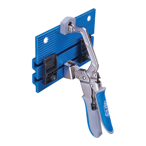
Introduction
Item# Description
Pièces
1
8
7
6
5
4
3
2
9
10
11
12
13
14
15
16
17
Bras de commande
Verrou du bras de commande
Base de l’outil
Poignées
Conduit d’aspiration
Vis autotaraudeuses
Collecteur d’aspiration
Vis à métaux à tête bombée
Colliers de serrage
Tuyau d’aspiration
Panneau d’accès
Dessus de l’outil
Clé hexagonale de 3 mm
Dispositifs de nivellement du couvercle
Leviers de blocage du guide d’un quart de tour
Guide
Vis de blocage du guide
Bases des vis de blocage du guide
Marques indiquant l’épaisseur de la pièce à travailler
Foret
Bouton de blocage de la profondeur de perçage
Bloc d’appui de la profondeur de perçage
Guide-foret (guide standard inclus)
Contre-écrou de la butée de profondeur
Boîtier du bras du serre-joint
Tampon du serre-joint
Bouton de réglage du serre-joint
Contre écrou du serre-joint
Bras du serre-joint
Bouton du verrou de sécurité de l’interrupteur
Interrupteur
Butées de pièce à travailler
Ruban à mesurer à lecture centrale
Embout de tournevis carré nº 2 de 6 po
Plateau à accessoires
Pied
Trou de montage
Support du panneau
Goupille de déverrouillage
Moteur
Tiges de guidage
Mandrin à changement rapide
Tige de raccord du moteur
Pivots
Logements des pivots
Vis de calage du guide-foret
18
Item# Description
20
19
28
31
38
37
36
35
34
33
32
39
21
22
23
24
25
26
27
29
Félicitations pour votre achat de l’outil pour perçage en angle semi-automatique Foreman DB210 de Kreg. Avant d’utiliser cet article, lisez
toutes les instructions et les consignes de sécurités contenues dans le présent manuel.
Lorsque vous possédez un outil Foreman, vous protez de tous les avantages d’un véritable outil pour perçage en angle industriel, ainsi que
de la petite taille et de la portabilité d’un outil d’établi. Le présent manuel vous guidera à travers toutes les étapes nécessaires pour régler
votre outil et percer des trous en angle. En plus de celles contenues dans ce manuel, les ressources suivantes pourraient vous être utiles :
30
40
41
42
43
44
45
Kreg en ligne : pour commander des vis pour perçage en angle, voir les accessoires oerts pour votre gabarit ou savoir
comment faire un joint en particulier, visitez le site kregtool.com.
Communauté des propriétaires de Kreg : inscrivez-vous en tant que membre, créez votre propre page, regardez les
projets des autres membres, achez les photos de vos projets, visionnez des vidéos d’instructions et participez à des forums
en vous rendant au kregjig.ning.com.
Chaîne YouTube de Kreg : pour des projets, des produits et des vidéos d’instructions, visitez le site youtube.com/user/
kregtoolcompany.
Kreg sur Facebook : prenez contact avec Kreg sur Facebook an de partager vos projets et de vous inspirer de nos
admirateurs et amis sur facebook.com/kregJig.
46

Pièces
10
6
5
7
4
32
32
36
37
11
4
15
25
31
30
1
33
16
15
29
28
27
922
34
13
8
12
26
23
21
17
17
3

Pièces
4
2
24
15
21
25
15
19
3
40
4
35
39
38
14
43
46
14
23
41
20
Table of contents
Languages:
Other Kreg Tools manuals

Kreg
Kreg KFPCHB User manual

Kreg
Kreg R3-INT User manual

Kreg
Kreg KMA4000 User manual

Kreg
Kreg Jig K4 User manual

Kreg
Kreg MINI KREG JIG User manual

Kreg
Kreg KMA3225 User manual

Kreg
Kreg K3 Operating and maintenance manual

Kreg
Kreg PRS1000 User manual

Kreg
Kreg Adaptive Cutting System Rip Guides User manual

Kreg
Kreg Rip-Cut KMA2685 User manual

Kreg
Kreg KHI-PULL-INT User manual

Kreg
Kreg K4 User manual

Kreg
Kreg DB55 Operating and maintenance manual

Kreg
Kreg Jig HD User manual

Kreg
Kreg KPHJ310 User manual

Kreg
Kreg KPHA740 User manual

Kreg
Kreg Klamp Plate Service manual

Kreg
Kreg 700 Series User manual

Kreg
Kreg 720PRO User manual

Kreg
Kreg KPHJ230 User manual