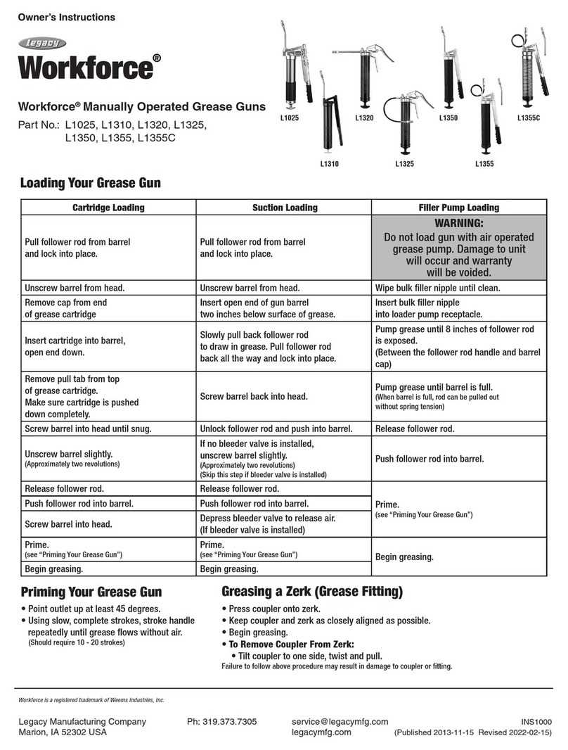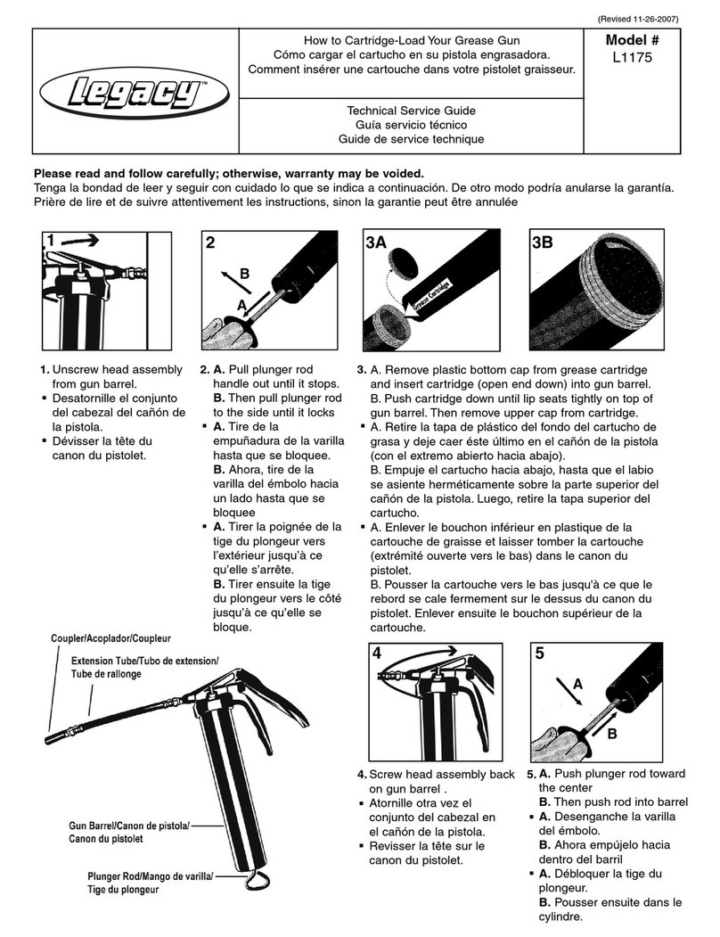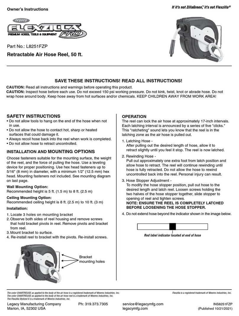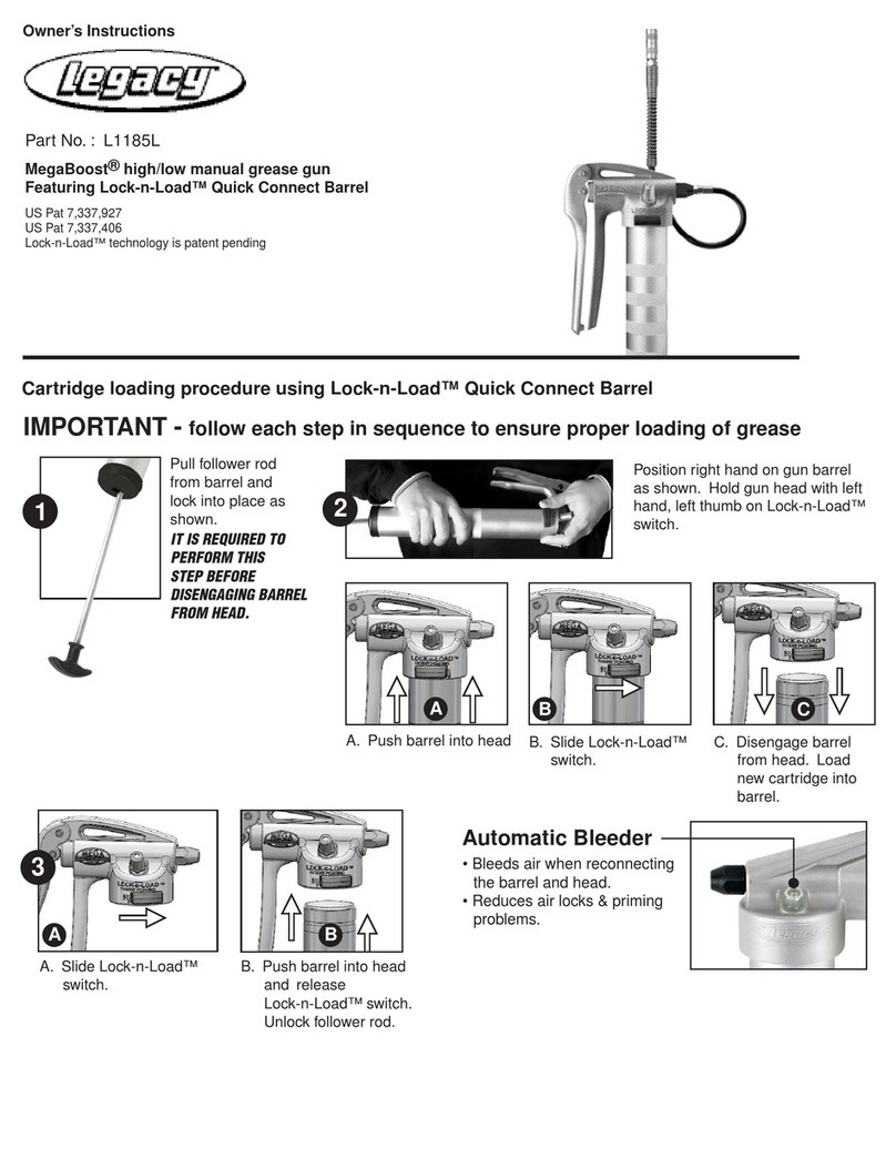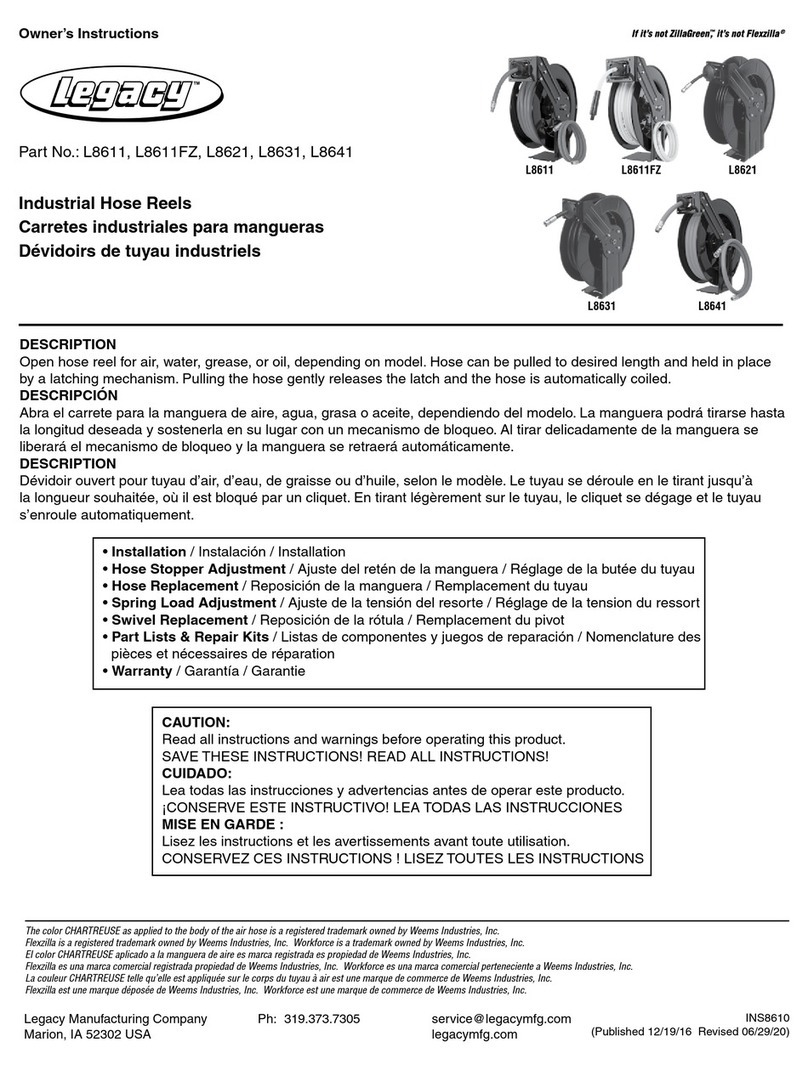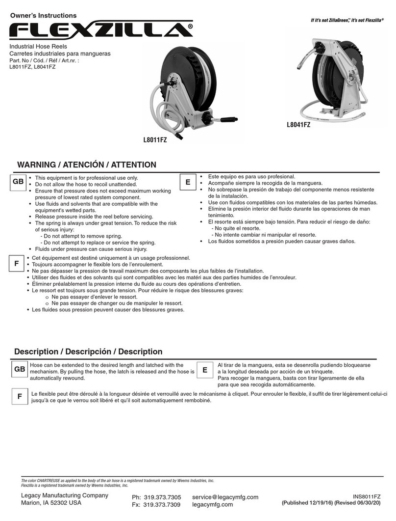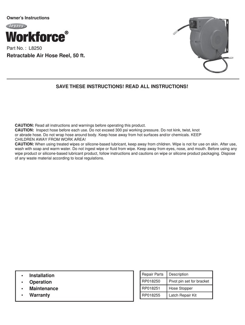
INSTALLATION
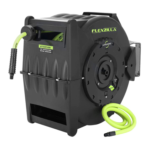
The hose reel can be bench, wall, high wall or ceiling mounted.
The hose guide arm and the hose outlet opening must be
positioned according to Fig. A to ensure a smooth operation of
the reel and to increase the hose life. To move the hose guide
arm and the hose outlet opening, the screws marked with an
arrow on Fig. B must be removed. Move the arm and hose
outlet to its correct position, replace screws and tighten.
HOSE STOPPER ADJUSTMENT
To modify the hose stopper position, pull out hose to the
desired length and latch reel. Loosen the hose stopper and
place it at the opening of the hose guide. NOTE: CHECK THAT
THE REEL IS PERFECTLY LATCHED BEFORE REMOVING THE
HOSE STOPPER.
HOSE REPLACEMENT
CAUTION: REEL IS SPRING-LOADED. INJURY WILL RESULT
IF YOU DO NOT MAINTAIN CONTROL OF REEL AND HOSE AT
ALL TIMES.
1. Unwind hose completely then allow it to rewind to the rst
locked position. Secure vise grips or other device on spool
assembly, near the guide arm assembly to prevent the reel
from retracting. DO NOT CRUSH LIP.
2. Remove hose from the reel. Insert new hose through hole in
spool and attach clamps. Attach hose stop.
3. With one hand on the hose remove the vise grips and allow
the hose to rewind.
4. Once service gun is installed, verify that the spring tension is
adequate. If the spring tension is not adequate, follow the
steps below to add additional spring tension.
SPRING LOAD ADJUSTMENT
1. The hose reels are supplied with a spring tension, which is
factory adjusted according to the hose. If the spring tension
is to be adjusted afterwards CHECK that the required length
of the hose can be pulled out WITHOUT STRETCHING THE
PRING TO THE LIMIT. The lowest spring tension possible
increases the life of the spring.
2. Too much spring tension will shorten the life of the spring
and put excessive wear and tear on the hose. Do not exceed
18 turns from unwound position.
3. To adjust tension, pull out approximately 6 ft. or 2 m of hose
and allow the drum to latch.
4. Remove hose stopper from hose and feed hose back
through guide.
5. Wrap the pulled hose one more time around the drum to
increase tension, or un-wrap hose one time from drum to
decrease tension.
6. Re-feed hose through guide and install hose stopper.
7. Unlatch drum and check tension. Pull hose from reel, and
adjust stopper position if necessary.
SWIVEL REPLACEMENT
IMPORTANT: BEFORE REMOVING THE OLD SWIVEL, CLOSE
THE NEAREST CONTROL VALVE TO THE REEL AND OPEN
THE FLUID CONTROL GUN TO RELEASE THE PRESSURE
INSIDE THE GUN AND HOSE.
1. With the hose completely coiled, remove the uid inlet hose
and the old swivel (Fig. C).
2. Replace the old swivel with the new one.
3. To tighten the swivel, hold the reel drum while you tighten it
(Fig. D).
4. Connect the inlet hose again.
PRESSURE RATINGS at 70°F / 21°C:
Working Pressure
L8603FZ 300 PSI
INSTALLATION
Le dévidoir peut être monté sur un établi, un mur, un mur en hauteur ou
au plafond. Le bras de guidage du tuyau et l’embouchure de sortie du
tuyau peuvent être placés dans les positions indiquées sur la gure A
pour assurer un fonctionnement en douceur du dévidoir et augmenter
la durabilité du tuyau. Pour modier la
position du bras de guidage et de l’embouchure, déposer les vis dé-
signées par une èche sur la gure B. Placer le bras et l’embouchure
dans la position souhaitée, remettre les vis en place et serrer.
RÉGLAGE DE LA BUTÉE DU TUYAU
Pour modier la position de la butée du tuyau, extraire la longueur de
tuyau désirée et verrouiller le dévidoir. Desserrer la butée et la placer
à l’embouchure du guide de tuyau. REMARQUE : VÉRIFIER QUE LE
DÉVIDOIR EST CORRECTEMENT VERROUILLÉ AVANT DE DÉPOSER
LA BUTÉE DU TUYAU.
REMPLACEMENT DE TUYAU
MISE EN GARDE : LE DÉVIDOIR COMPORTE UN RESSORT DE RAP-
PEL. POUR ÉCARTER LES RISQUES DE BLESSURE, VEILLER À TOU-
JOURS BIEN MAÎTRISER LE DÉVIDOIR ET LE TUYAU.
1. Dérouler complètement le tuyau et le laisser s’enrouler jusqu’à
sa première position de blocage. Attacher une pince-étau ou
autre dispositif semblable sur la bobine à proximité du bras de
guidage pour empêcher l’enroulement automatique. NE PAS
ÉCRASER LA LÈVRE.
2. Enlever le tuyau du dévidoir. Introduire le tuyau neuf à travers
l’orice dans la bobine et poser le collier de serrage. Attacher
la butée de tuyau.
3. En tenant le tuyau d’une main, enlever la pince-étau et laisser
le tuyau s’enrouler.
4. Une fois que le pistolet est posé, vérier que la tension du
ressort est sufsante. Si la tension n’est pas sufsante, suivre
les instructions ci-dessous pour l’augmenter.
RÉGLAGE DE LA TENSION DU RESSORT
1. Les dévidoirs sont livrés avec une tension de ressort réglée
d’usine en fonction du tuyau. Si la tension du ressort doit être
réglée par la suite, VÉRIFIER que la longueur de tuyau
souhaitée peut être extraite SANS ÉTIRER LE RESSORT
JUSQU’À SA LIMITE. La durée de vie du ressort sera d’autant
plus longue quesa tension est faible.
2. Une tension trop élevée raccourcira la durée de vie du ressort
et produira une usure excessive du tuyau. Ne pas dépasser 18
tours à partir de la position complètement déroulée.
3. Pour régler la tension, extraire environ 2 m de tuyau et laisser
le tambour se bloquer.
4. Déposer la butée du tuyau et repousser le tuyau à travers le
guide.
5. Enrouler le tuyau extrait d’un tour supplémentaire sur le
tambour pour augmenter la tension ou le dérouler d’un tour sur
le tambour pour diminuer la tension.
6. Refaire passer le tuyau à travers le guide et reposer la butée
du tuyau.
7. Débloquer le tambour et contrôler la tension. Tirer le tuyau du
dévidoir et régler le cas échéant la position de la butée.
REMPLACEMENT DU PIVOT
IMPORTANT : AVANT DE DÉPOSER LE PIVOT USAGÉ, FERMER LE
ROBINET LE PLUS PROCHE DU DÉVIDOIR ET OUVRIR LE PISTOLET
POUR LIBÉRER LA PRESSION À L’INTÉRIEUR DU PISTOLET ET DU
TUYAU.
1. Le tuyau étant complètement enroulé, déposer le tuyau
d’arrivée de uide et le pivot usagé (Fig. C).
2. Remplacer le pivot usagé par le pivot neuf.
3. Tenir le tambour du dévidoir pour serrer le pivot (Fig. D).
4. Rebrancher le tuyau d’arrivée.
PRESSION NOMINALE de 70°F / 21°C:
Pression de service
L8603FZ 300 PSI / 21 bar
REPAIR PARTS
Repair Part Description
RP001071 Swivel kit
RP001075 Guide roller kit
HFZ3825YW2 3/8 in. x 25 ft. air hose
