manuals.online logo
Brands
  1. Home
  2. •
  3. Brands
  4. •
  5. Legacy
  6. •
  7. Tools
  8. •
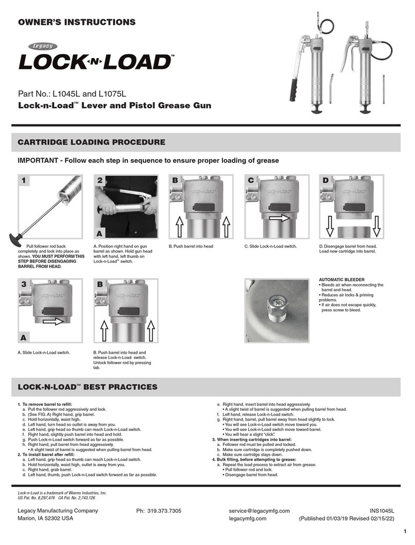
  9. Legacy Workforce L8602 User manual

Legacy Workforce L8602 User manual

Owner’s Instructions / Instructivo del propietario / Instructions d’utilisation
1
Legacy Manufacturing Company
Marion, IA 52302 USA
Ph: 319.373.7305
Fx: 319.373.7309
ser[email protected]
legacymfg.com
INS8600
(Published 12/19/16 Revised 06/24/20)
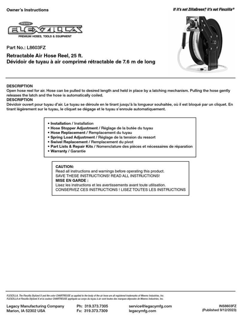
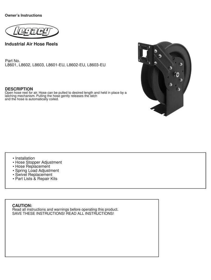
DESCRIPTION
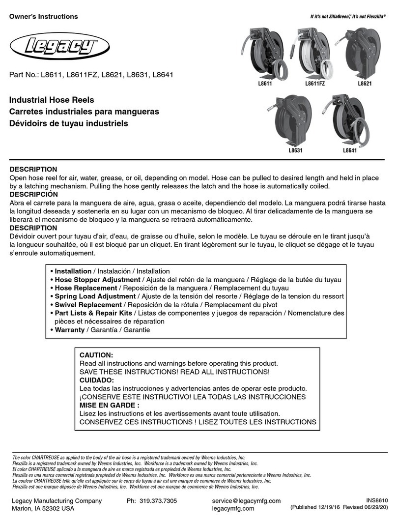
Open hose reel for air. Hose can be pulled to desired length and held in place by a
latching mechanism. Pulling the hose gently releases the latch and the hose is
automatically coiled.
DESCRIPCIÓN
Abra el carrete para la manguera de aire. La manguera podrá tirarse hasta la
longitud deseada y sostenerla en su lugar con un mecanismo de bloqueo. Al tirar
delicadamente de la manguera se liberará el mecanismo de bloqueo y la manguera
se retraerá automáticamente.
DESCRIPTION
Dévidoir ouvert pour tuyau d’air. Le tuyau se déroule en le tirant jusqu’à la longueur
souhaitée, où il est bloqué par un cliquet. En tirant légèrement sur le tuyau, le cliquet
se dégage et le tuyau s’enroule automatiquement.
• Installation / Instalación / Installation
• Hose Stopper Adjustment / Ajuste del retén de la manguera / Réglage de la butée du tuyau
• Hose Replacement / Reposición de la manguera / Remplacement du tuyau
• Spring Load Adjustment / Ajuste de la tensión del resorte / Réglage de la tension du ressort
• Swivel Replacement / Reposición de la rótula / Remplacement du pivot
• Part Lists & Repair Kits / Listas de componentes y juegos de reparación / Nomenclature des pièces et nécessaires de réparation
• Warranty / Garantía / Garantie
CAUTION:
Read all instructions and warnings before operating this product.
SAVE THESE INSTRUCTIONS! READ ALL INSTRUCTIONS!
CUIDADO:
Lea todas las instrucciones y advertencias antes de operar este producto.
¡CONSERVE ESTE INSTRUCTIVO! LEA TODAS LAS INSTRUCCIONES
MISE EN GARDE :
Lisez les instructions et les avertissements avant toute utilisation.
CONSERVEZ CES INSTRUCTIONS ! LISEZ TOUTES LES INSTRUCTIONS
Retractable Air Hose Reel, 50 ft.
Carrete retráctil para mangueras de aire de 15 m
Dévidoir de tuyau à air comprimé rétractable de 15 m de long
Part No. / Comp. Núm. / Nos de réf. : L8602
Workforce is a registered trademark owned by Weems Industries, Inc.
INSTALLATION
The hose reel can be bench, wall, high wall or ceiling mounted.
The hose guide arm and the hose outlet opening must be
positioned according to Fig. A to ensure a smooth operation of
the reel and to increase the hose life. To move the hose guide arm
and the hose outlet opening, the screws marked with an arrow
on Fig. B must be removed. Move the arm and hose outlet to its
correct position, replace screws and tighten.
HOSE STOPPER ADJUSTMENT
To modify the hose stopper position, pull out hose to the desired
length and latch reel. Loosen the hose stopper and place it at
the opening of the hose guide. NOTE: CHECK THAT THE REEL
IS PERFECTLY LATCHED BEFORE REMOVING THE HOSE
STOPPER.
HOSE REPLACEMENT
CAUTION: REEL IS SPRING-LOADED. INJURY WILL RESULT
IF YOU DO NOT MAINTAIN CONTROL OF REEL AND HOSE AT
ALL TIMES.
1. Unwind hose completely then allow it to rewind to the first
locked position. Secure vise grips or other device on spool
assembly, near the guide arm assembly to prevent the reel
from retracting. DO NOT CRUSH LIP.
2. Remove hose from the reel. Insert new hose through hole in
spool and attach clamps. Attach hose stop.
3. With one hand on the hose remove the vise grips and allow the
hose to rewind.
4. Once service gun is installed, verify that the spring tension is
adequate. If the spring tension is not adequate, follow the steps
below to add additional spring tension.
SPRING LOAD ADJUSTMENT
1. The hose reels are supplied with a spring tension, which is fac
tory adjusted according to the hose. If the spring tension is to
be adjusted afterwards CHECK that the required length of the
hose can be pulled out WITHOUT STRETCHING THE PRING
TO THE LIMIT. The lowest spring tension possible increases
the life of the spring.
2. Too much spring tension will shorten the life of the spring and
put excessive wear and tear on the hose. Do not exceed 18
turns from unwound position.
3. To adjust tension, pull out approximately 6 ft. or 2 m of hose
and allow the drum to latch.
4. Remove hose stopper from hose and feed hose back through
guide.
5. Wrap the pulled hose one more time around the drum to
increase tension, or un-wrap hose one time from drum to
decrease tension.
6. Re-feed hose through guide and install hose stopper.
7. Unlatch drum and check tension. Pull hose from reel, and
adjust stopper position if necessary.
SWIVEL REPLACEMENT
IMPORTANT: BEFORE REMOVING THE OLD SWIVEL, CLOSE
THE NEAREST CONTROL VALVE TO THE REEL AND OPEN
THE FLUID CONTROL GUN TO RELEASE THE PRESSURE
INSIDE THE GUN AND HOSE.
1. With the hose completely coiled, remove the fluid inlet hose
and the old swivel (Fig. C).
2. Replace the old swivel with the new one.
3. To tighten the swivel, hold the reel drum while you tighten it
(Fig. D).
4. Connect the inlet hose again.
INSTALACIÓN
El carrete de la manguera podrá instalarse en un banco de
trabajo, sobre un muro o en el techo. El brazo de la guía de la
manguera y la abertura de la salida de la manguera deberán
colocarse según la ilustración A, para garantizar la operación fácil
del carrete y extender la vida útil de la manguera. Será necesario
extraer los tornillos señalados con una flecha en la ilustración B,
para mover el brazo de la guía de la manguera y la abertura de la
salida de la manguera. Mueva el brazo y la salida de la manguera
hasta su posición correcta, reinstale los tornillos y apriételos.
AJUSTE DEL RETÉN DE LA MANGUERA
Si desea modificar la posición del retén de la manguera, tire de la
manguera hasta la longitud deseada y bloquee el carrete con el
fiador. Afloje el retén de la manguera y colóquelo en la abertura
de la guía de la manguera.
NOTA:
REVISE QUE EL CARRETE ESTÉ PERFECTAMENTE BLOQUEADO
ANTES DE EXTRAER EL RETÉN DE LA MANGUERA.
REPOSICIÓN DE LA MANGUERA
CUIDADO: EL CARRETE CONTIENE UN RESORTE CON
TENSIÓN. SI NO MANTIENE EL CONTROL DEL CARRETE Y
LA MANGUERA, EN TODO MOMENTO, PUDIERA DAR COMO
RESULTADO QUE USTED SE LESIONE.
1. Desenrolle la manguera totalmente y permita que se retraiga
hasta la primera posición de bloqueo. Coloque unas pinzas de
presión o cualquier otro dispositivo en el ensamble del carrete,
cerca del ensamble del brazo de guía y prevenir así que el carrete
se retraiga. EVITE APLASTAR EL LABIO.
2. Saque la manguera del carrete. Inserte una manguera nueva
a través del agujero en el carrete y colóquele las abrazaderas.
Colóquele el retén de la manguera.
3. Con una mano sosteniendo la manguera, quite las pinzas de
presión y permita que la manguera se retraiga.
4. Una vez que haya instalado la pistola que estará en servicio,
verifique que la tensión del resorte sea la adecuada. Si la tensión
del resorte no es la adecuada, siga los pasos a continuación para
aumentar la tensión del resorte.
AJUSTE DE LA TENSIÓN DEL RESORTE
1. Los carretes para mangueras se surten con cierta tensión en
el re sorte, misma que se ajusta desde la fábrica, según el tipo
de manguera. Si considera necesario posteriormente ajustar la
tensión del resorte, VERIFIQUE que pueda tirar de la
manguera a la longitud necesaria SIN ESTIRAR EL RESORTE
HASTA SU LÍMITE. La tensión más baja del resorte que le sea
posible, incrementará la vida útil del resorte.
2. Demasiada tensión en el resorte acortará la vida del resorte,
des gastará excesivamente y romperá la manguera. No exceda
18 vueltas desde su posición sin retraerse.
3. Si desea ajustar la tensión, tire de la manguera a una longitud
de 6 pies ó 2 metros y permita que se bloquee el tambor.
4. Extraiga el retén de la manguera y vuelva a retraer la
manguera a través de la guía.
5. Vuelva a enrollar una vuelta más la manguera restante por
encima del tambor, para incrementar la tensión, o desenrolle la
manguera una vuelta por encima del tambor para disminuir la
tensión.
6. Vuelva enrollar la manguera a través de la guía e instale el
retén de la manguera.
7. Desbloquee el tambor y verifique la tensión. Tire la manguera
en el carrete y si es necesario, ajuste la posición del retén.
REPOSICIÓN DE LA RÓTULA
IMPORTANTE: ANTES DE EXTRAER LA RÓTULA ANTERIOR,
CIERRE LA VÁLVULA DE CONTROL MÁS CERCANA AL
CARRETE Y ABRA EL CONTROL DE FLUJO DE LA PISTOLA,
PARA DESCARGAR LA PRESIÓN DENTRO DE LA PISTOLA Y
LA MANGUERA.
1. Con la manguera totalmente retraída en el carrete, extraiga la
manguera de abasto del líquido y la rótula anterior
(Ilustración C).
2. Sustituya la rótula anterior con la nueva.
3. Sostenga el tambor del carrete mientras aprieta la rótula
(Ilustración D).
4. Conecte nuevamente la manguera de abasto.
PRESSURE RATINGS at 70°F / 21°C:
Working Pressure
L8602 300 PSI PRESIÓN NOMINAL a 70°F / 21°C:
Presión de trabajo
L8602 300 PSI / 21 barios
REPAIR PARTS
Repair Part Description
RP001071 Swivel kit
RP001075 Guide roller kit
RP001076 3/8 in. x 25 ft. air hose
INSTALLATION
Le dévidoir peut être monté sur un établi, un mur, un mur en hauteur ou au
plafond. Le bras de guidage du tuyau et l’embouchure de sortie du tuyau
peuvent être placés dans les positions indiquées sur la figure A pour as-
surer un fonctionnement en douceur du dévidoir et augmenter la durabilité
du tuyau. Pour modifier la
position du bras de guidage et de l’embouchure, déposer les vis dé-
signées par une flèche sur la figure B. Placer le bras et l’embouchure dans
la position souhaitée, remettre les vis en place et serrer.
RÉGLAGE DE LA BUTÉE DU TUYAU
Pour modifier la position de la butée du tuyau, extraire la longueur de
tuyau désirée et verrouiller le dévidoir. Desserrer la butée et la placer
à l’embouchure du guide de tuyau. REMARQUE : VÉRIFIER QUE LE
DÉVIDOIR EST CORRECTEMENT VERROUILLÉ AVANT DE DÉPOSER
LA BUTÉE DU TUYAU.
REMPLACEMENT DE TUYAU
MISE EN GARDE : LE DÉVIDOIR COMPORTE UN RESSORT DE
RAPPEL. POUR ÉCARTER LES RISQUES DE BLESSURE, VEILLER À
TOUJOURS BIEN MAÎTRISER LE DÉVIDOIR ET LE TUYAU.
1. Dérouler complètement le tuyau et le laisser s’enrouler jusqu’à
sa première position de blocage. Attacher une pince-étau ou
autre dispositif semblable sur la bobine à proximité du bras de
guidage pour empêcher l’enroulement automatique. NE PAS
ÉCRASER LA LÈVRE.
2. Enlever le tuyau du dévidoir. Introduire le tuyau neuf à travers
l’orifice dans la bobine et poser le collier de serrage. Attacher
la butée de tuyau.
3. En tenant le tuyau d’une main, enlever la pince-étau et laisser
le tuyau s’enrouler.
4. Une fois que le pistolet est posé, vérifier que la tension du
ressort est suffisante. Si la tension n’est pas suffisante, suivre
les instructions ci-dessous pour l’augmenter.
RÉGLAGE DE LA TENSION DU RESSORT
1. Les dévidoirs sont livrés avec une tension de ressort réglée
d’usine en fonction du tuyau. Si la tension du ressort doit être
réglée par la suite, VÉRIFIER que la longueur de tuyau
souhaitée peut être extraite SANS ÉTIRER LE RESSORT
JUSQU’À SA LIMITE. La durée de vie du ressort sera d’autant
plus longue quesa tension est faible.
2. Une tension trop élevée raccourcira la durée de vie du ressort
et produira une usure excessive du tuyau. Ne pas dépasser 18
tours à partir de la position complètement déroulée.
3. Pour régler la tension, extraire environ 2 m de tuyau et laisser
le tambour se bloquer.
4. Déposer la butée du tuyau et repousser le tuyau à travers le
guide.
5. Enrouler le tuyau extrait d’un tour supplémentaire sur le
tambour pour augmenter la tension ou le dérouler d’un tour sur
le tambour pour diminuer la tension.
6. Refaire passer le tuyau à travers le guide et reposer la butée
du tuyau.
7. Débloquer le tambour et contrôler la tension. Tirer le tuyau du
dévidoir et régler le cas échéant la position de la butée.
REMPLACEMENT DU PIVOT
IMPORTANT : AVANT DE DÉPOSER LE PIVOT USAGÉ, FERMER LE
ROBINET LE PLUS PROCHE DU DÉVIDOIR ET OUVRIR LE PISTOLET
POUR LIBÉRER LA PRESSION À L’INTÉRIEUR DU PISTOLET ET DU
TUYAU.
1. Le tuyau étant complètement enroulé, déposer le tuyau
d’arrivée de fluide et le pivot usagé (Fig. C).
2. Remplacer le pivot usagé par le pivot neuf.
3. Tenir le tambour du dévidoir pour serrer le pivot (Fig. D).
4. Rebrancher le tuyau d’arrivée.
PRESSION NOMINALE de 70°F / 21°C:
Pression de service
L8602 300 PSI / 21 bar
LEGACY MANUFACTURING COMPANY (“LEGACY”) warrants that this
equipment will be free from defects in material and workmanship for a
period of two (2) years from the date of purchase, under normal use.*
LEGACY’S sole obligation under this warranty is limited to replacing or
repairing, free of charge, any equipment that proves to be defective under
normal conditions and use according to the recommendations of LEGACY.
To obtain repair or replacement, the equipment must be shipped to a
LEGACY authorized Warranty and Service Center during the warranty
period, transportation charges prepaid, with proof of date of purchase.
In the event of repair or replacement, the warranty period shall not be
extended beyond the original warranty period. This warranty is extended
to the original purchaser only and is not transferable. This warranty does
not apply to normal wear items such as packings, seals, tips and filters,
or to equipment damaged from accident, overload, abuse, misuse,
negligence, faulty installation or abrasive or corrosive materials, or to
equipment repaired or altered by anyone not authorized by LEGACY to
repair and alter equipment. No allowance will be granted for any repairs or
alterations made by a purchaser without LEGACY’S prior written consent.
Unless modified in a writing, signed by both parties, this Limited Warranty
is understood to be the complete and exclusive agreement between the
parties, superseding all prior agreements, oral or written, and all other
communications between the parties relating to the subject matter of this
Limited Warranty. Any action for breach of warranty must be commenced
within twelve (12) months following the end of the warranty period.
* If this equipment contains a hose, the hose is warranted for ninety
(90) days only. The remaining portions of this equipment are warranted
for two (2) years, as described above. While necessary maintenance or
repairs on your Legacy equipment can be performed by any company, we
recommend that you use only authorized Legacy service centers.
Improper or incorrectly performed maintenance or repair voids this
warranty. Contact us at [email protected] or
www.legacymfg.com for ordering, installation instructions.
WARRANTY
TWO YEAR LIMITED WARRANTY*
LEGACY MANUFACTURING COMPANY (“LEGACY”) garantiza
durante un periodo de dos (2) años a partir de la fecha de adquisición, y
bajo condiciones normales de uso, que este equipo no tiene ningún de-
fecto en sus materiales y mano de obra*. La única obligación de LEGACY,
según esta garantía, se limita a sustituir o reparar sin costo alguno, cual-
quier equipo que se haya comprobado estar defectuoso bajo condiciones
normales de uso según las recomendaciones hechas por LEGACY. Con
el fin de reparar o sustituir dicho equipo, el equipo deberá ser enviado a
un Centro de Servicio y Garantía LEGACY autorizado durante la vigencia
de la garantía, el costo de los fletes pagados y acompañado del compro-
bante de compra con la fecha de adquisición. En caso de una reparación
o sustitución, el periodo de garantía no deberá extenderse más allá del
periodo original de su vigencia. Esta garantía se le extiende solamente al
adquiriente original y no es transferible. Esta garantía no le será pertinente
a los artículos que normalmente se desgastan como lo son los empaques,
sellos, casquillos y filtros, ni al equipo dañado a consecuencia de un ac-
cidente, sobrecarga, abuso, mal uso, negligencia, instalación defectuosa o
los efectos de materiales abrasivos o corrosivos, ni
al equipo reparado o modificado por cualquier persona ajena no autor-
izada por LEGACY para reparar o alterar dicho equipo. No se le otorgará
ninguna concesión por concepto de ninguna reparación o alteración
hecha por el adquiriente sin el previo consentimiento por escrito de
LEGACY. Salvo que se modifique por escrito y firmado por ambas partes,
esta garantía limitada deberá interpretarse como un convenio completo
y exclusivo entre las partes, invalidando todo convenio previo, ya sea
expresado o por
escrito y cualesquiera otras comunicaciones entre las partes que estén re-
lacionadas con el asunto sujeto a esta garantía limitada. Cualquier acción
o incumplimiento de la garantía deberá darse por iniciada(o) dentro de los
doce (12) meses posteriores al término del periodo de la garantía.
* Si este equipo está equipado con una manguera, la vigencia de la
garantía de la manguera será solamente de noventa (90) días. El resto
de los componentes de este equipo se garantizan durante dos (2) años,
como se indicó anteriormente. Dado que el mantenimiento y reparación
de su equipo Legacy podrá ser hecho por cualquier empresa, le reco-
mendamos que acuda solamente a los distribuidores Legacy autorizados.
Las labores de mantenimiento o reparaciones inapropiadas o incorrectas
invalidarán
la garantía. Comuníquese con nosotros a ser[email protected] ó www.
legacymfg.com si desea hacer un pedido, instrucciones para la insta-
lación.
GARANTÍA
GARANTÍA LIMITADA A DOS AÑOS*
La société LEGACY MANUFACTURING COMPANY (“ LEGACY “)
garantit que, dans des conditions normales d’utilisation, ce ma-
tériel sera exempt de vice de matière et de fabrication pendant
2 (deux) ans à partir de la date d’achat*. En vertu de la présente
garantie, la seule obligation de la société LEGACY se limite
à remplacer ou à réparer gratuitement le matériel se révélant
défectueux à la suite d’une utilisation normale, effectuée dans des
conditions normales et conformément aux recommandations de
la société LEGACY. Pour toute réparation ou remplacement, le
matériel doit être expédié pendant la période de garantie à un
centre de service sous garantie agréé par la société LEGACY
et doit être accompagné d’une preuve de la date d’achat, les
frais de transport ayant été prépayés. En cas de réparation ou
de remplacement, la période de garantie n’est pas prolongée
au-delà de la période de garantie d’origine. La présente garantie
ne s’applique qu’à l’acheteur originel et n’est pas transférable. La
présente garantie ne s’applique pas aux éléments sujets à une
usure normale, tels que les garnitures, les joints, les embouts
et les filtres, ni au matériel endommagé à la suite d’un accident,
d’une surcharge, d’une utilisation abusive, d’une utilisation incor-
recte, de négligence, d’une installation incorrecte, de l’action
de matières abrasives ou corrosives, ni au matériel réparé ou
modifié par quiconque non agréé par la société LEGACY pour la
réparation et la modification du matériel. Aucune facilité ne sera
accordée en cas de réparation ou de modification effectuée par
un acheteur en l’absence d’une autorisation écrite préalable de
la société LEGACY. Sauf en cas de modification par écrit signée
par les deux parties, la présente garantie limitée constitue l’accord
complet et exclusif entre les parties, et remplace tout autre accord
verbal ou écrit précédent, et toute autre communication entre les
parties relative au domaine couvert par la présente garantie. Tout
recours pour l’inobservation d’une garantie doit être intenté dans
les 12 (douze) mois suivant la fin de la période de garantie.
* Si ce matériel comprend un tuyau flexible, celui-ci n’est
garanti que pour quatre-vingt-dix (90) jours. Les autres éléments
de ce matériel sont garantis pour 2 (deux) ans conformément aux
stipulations ci-dessus. Bien que toute entreprise puisse effectuer
l’entretien ou les réparations nécessaires du matériel Legacy,
nous recommandons d’avoir recours uniquement aux concession-
naires agréés par la société Legacy. Un entretien ou des répara-
tions inappropriés ou mal exécutés annulent la présente
garantie. Prendre contact avec nous à l’adresse service@lega-
cymfg.com ou www.legacymfg.com pour les commandes, les
instructions d’installation.
GARANTIE
GARANTIE LIMITÉE DE DEUX ANS*

Other Legacy Tools manuals

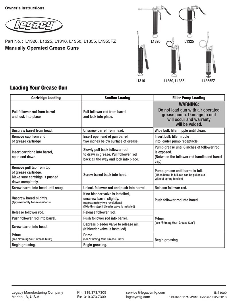
Legacy L1320 User manual

Legacy

Legacy L1320 User manual

Legacy L1175 User manual

Legacy

Legacy L1175 User manual

Legacy Lock-n-Load L1380L User manual

Legacy

Legacy Lock-n-Load L1380L User manual

Legacy Levelwind L8305 User manual

Legacy

Legacy Levelwind L8305 User manual

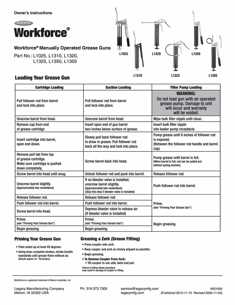
Legacy L1310 User manual

Legacy

Legacy L1310 User manual

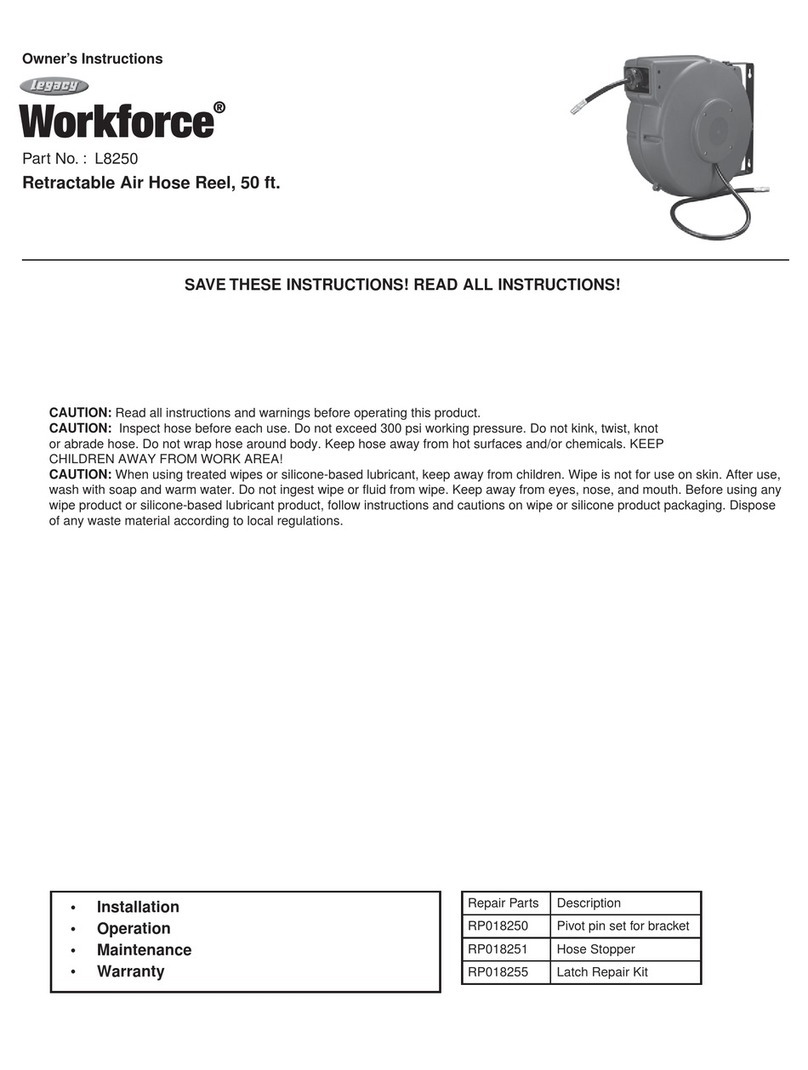
Legacy WorkForce L8250 User manual

Legacy

Legacy WorkForce L8250 User manual

Legacy Flexzilla L8011FZ User manual

Legacy

Legacy Flexzilla L8011FZ User manual

Legacy Lock-n-Load L1455L User manual

Legacy

Legacy Lock-n-Load L1455L User manual

Legacy L8611 User manual

Legacy

Legacy L8611 User manual

Legacy Lock-n-Load L1045L User manual

Legacy

Legacy Lock-n-Load L1045L User manual

Legacy Lock-n-Load L1175L User manual

Legacy

Legacy Lock-n-Load L1175L User manual

Legacy Flexzilla L8232FZ User manual

Legacy

Legacy Flexzilla L8232FZ User manual

Legacy FLEXZILLA PRO User manual

Legacy

Legacy FLEXZILLA PRO User manual

Legacy Workforce 1380 User manual

Legacy

Legacy Workforce 1380 User manual

Legacy MegaBoost L1185L User manual

Legacy

Legacy MegaBoost L1185L User manual

Legacy Flexzilla L1388LFZ User manual

Legacy

Legacy Flexzilla L1388LFZ User manual

Legacy MEGABOOST User manual

Legacy

Legacy MEGABOOST User manual

Legacy L8601 User manual

Legacy

Legacy L8601 User manual

Legacy FLEXZILLA L8603FZ User manual

Legacy

Legacy FLEXZILLA L8603FZ User manual

Legacy L8710 User manual

Legacy

Legacy L8710 User manual

Legacy L8611 User manual

Legacy

Legacy L8611 User manual

Legacy L1310 User manual

Legacy

Legacy L1310 User manual

Legacy L1355FZ User manual

Legacy

Legacy L1355FZ User manual

Popular Tools manuals by other brands

Cocraft 40-7819-1 instruction manual

Cocraft

Cocraft 40-7819-1 instruction manual

CLO FABRIC KIT manual

CLO

CLO FABRIC KIT manual

Sealey MS0381 instructions

Sealey

Sealey MS0381 instructions

Axminster Craft AC318BT Original instructions

Axminster Craft

Axminster Craft AC318BT Original instructions

Super Handy GUR026 instruction manual

Super Handy

Super Handy GUR026 instruction manual

Interface WTSTL Operator instructions

Interface

Interface WTSTL Operator instructions

Huck AEROBOLT FAR 10U05 quick start guide

Huck

Huck AEROBOLT FAR 10U05 quick start guide

Sealey AK7160 instructions

Sealey

Sealey AK7160 instructions

Schilling Multi-Marker Original operating manual

Schilling

Schilling Multi-Marker Original operating manual

Dynabrade 52573 Operation manual

Dynabrade

Dynabrade 52573 Operation manual

Duobond RL-eez manual

Duobond

Duobond RL-eez manual

Hard Head 013715 operating instructions

Hard Head

Hard Head 013715 operating instructions

Noha Model 1 Swinging Installation

Noha

Noha Model 1 Swinging Installation

Desoutter D53 Series Original instructions

Desoutter

Desoutter D53 Series Original instructions

BGS technic 7753 instruction manual

BGS technic

BGS technic 7753 instruction manual

WilTec 51800 user manual

WilTec

WilTec 51800 user manual

Atlas Copco RRD37 Product instructions

Atlas Copco

Atlas Copco RRD37 Product instructions

Engel 17 SLIDE instructions

Engel

Engel 17 SLIDE instructions

manuals.online logo
manuals.online logoBrands
  • About & Mission
  • Contact us
  • Privacy Policy
  • Terms and Conditions

Copyright 2025 Manuals.Online. All Rights Reserved.