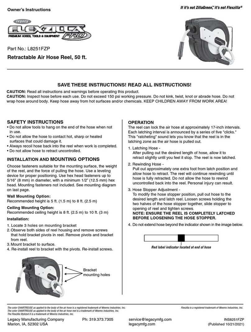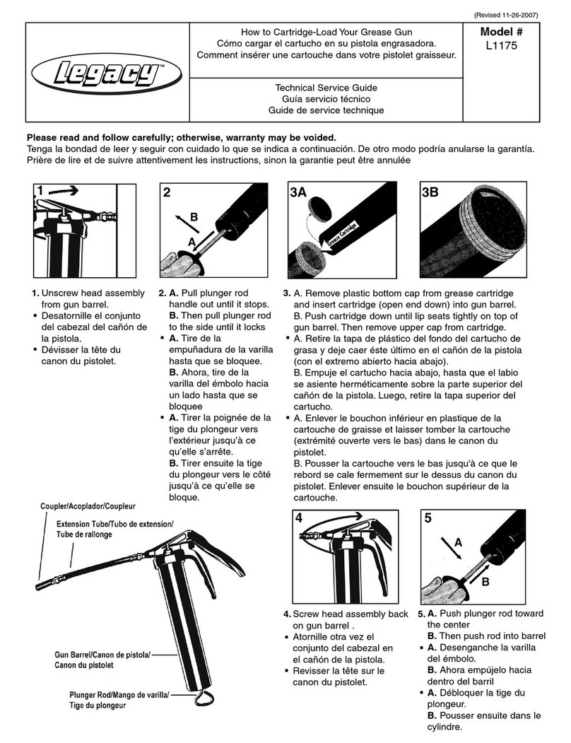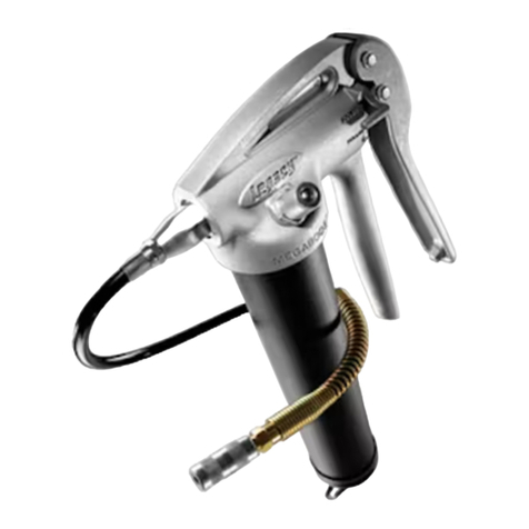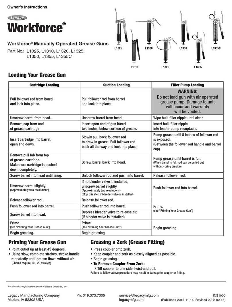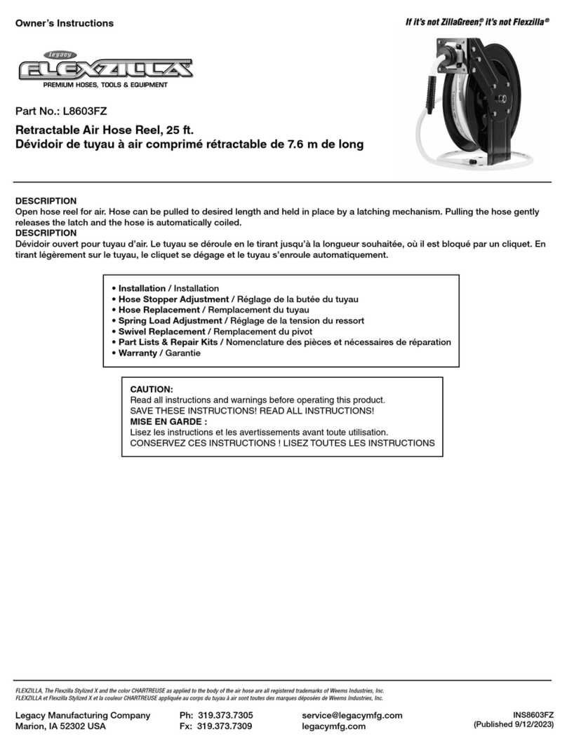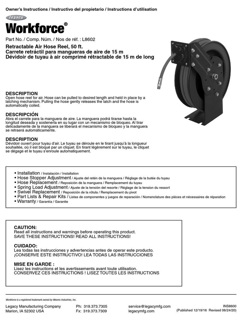
INSTALLATION
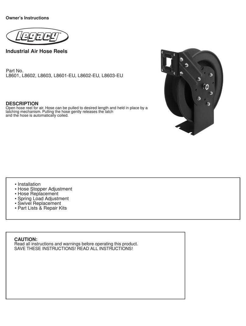
The hose reel can be bench, wall, high wall or ceiling mounted.The hose
guide arm and the hose outlet opening must be positioned according
to figure A to ensure a smooth operation of the reel and to increase the
hose life.To move the hose guide arm and the hose outlet opening, the
screws marked with an arrow on figure B must be removed. Move the arm
and hose outlet to its correct position, replace screws and tighten.
HOSE STOPPER ADJUSTMENT
To modify the hose stopper position, pull out hose to the desired length
and latch reel. Loosen the hose stopper and place it at the opening of the
hose guide.
NOTE: CHECK THAT THE REEL IS PERFECTLY LATCHED BEFORE
REMOVING THE HOSE STOPPER.
HOSE REPLACEMENT
CAUTION: REEL IS SPRING-LOADED. INJURY WILL RESULT IFYOU
DO NOT MAINTAIN CONTROL OF REEL AND HOSE AT ALL TIMES.
1. Unwind hose completely then allow it to rewind to the first locked
position. Secure vise grips or other device on spool assembly, near
the guide arm assembly to prevent the reel from retracting. DO NOT
CRUSH LIP.
2. Remove hose from the reel.Insert new hose through hole in spool and
attach clamps.Attach hose stop.
3.With one hand on the hose remove the vise grips and allow the hose to
rewind.
4. Once service gun is installed, verify that the spring tension is adequate.
If the spring tension is not adequate, follow the steps below to add ad-
ditional spring tension.
SPRING LOAD ADJUSTMENT
1.The hose reels are supplied with a spring tension, which is factory
adjusted according to the hose.If the spring tension is to be adjusted
afterwards CHECK that the required length of the hose can be pulled
out WITHOUT STRETCHING THE SPRING TO THE LIMIT.The lowest
spring tension possible increases the life of the spring.
2.Too much spring tension will shorten the life of the spring and put
excessive wear and tear on the hose. Do not exceed 18 turns from
unwound position.
3.To adjust tension, pull out approximately 6 ft.or 2 m of hose and allow
the drum to latch.
4. Remove hose stopper from hose and feed hose back through guide.
5.Wrap the pulled hose one more time around the drum to increase
tension, or un-wrap hose one time from drum to decrease tension. Do
not exceed 18 turns from unwound position.
6. Re-feed hose through guide and install hose stopper.
7. Unlatch drum and check tension.Pull hose from reel, and adjust
stopper position if necessary.
SWIVEL REPLACMENT
IMPORTANT:BEFORE REMOVING THE OLD SWIVEL, CLOSETHE
NEAREST CONTROLVALVE TO THE REEL AND OPEN THE FLUID
CONTROL GUNTO RELEASETHE PRESSURE INSIDE THE GUN AND
HOSE.
1.With the hose completely coiled, remove the fluid inlet hose and the old
swivel. (Fig. C).
2. Replace the old swivel with the new one.
3.To tighten the swivel, hold the reel drum while you tighten it. (Fig. D).
4. Connect the inlet hose again.
Working Pressure Burst Pressure
L8611, L8611FZ
300 PSI 1200 PSI
L8621 5000 PSI 20,000 PSI
L8631, L8632 2000 PSI 8000 PSI
L8641 300 PSI 1200 PSI
PRESSURE RATINGS at 68°F/ 20°C:
Lead-in Hoses:
L8611LI for reel L8611
L8621LI for reels L8620 and L8621
L8631LI for reels L8630, L8631 and L8632
L8611FZLI for reel L8611FZ
Bench
Truck Ceiling
Wall High Wall
